US6216729B1 - Bidirectional check valve for hydraulic system - Google Patents
Bidirectional check valve for hydraulic system Download PDFInfo
- Publication number
- US6216729B1 US6216729B1 US09/612,773 US61277300A US6216729B1 US 6216729 B1 US6216729 B1 US 6216729B1 US 61277300 A US61277300 A US 61277300A US 6216729 B1 US6216729 B1 US 6216729B1
- Authority
- US
- United States
- Prior art keywords
- poppet
- opening
- valve body
- passage
- fluid
- Prior art date
- Legal status (The legal status is an assumption and is not a legal conclusion. Google has not performed a legal analysis and makes no representation as to the accuracy of the status listed.)
- Expired - Fee Related
Links
Images


Classifications
-
- F—MECHANICAL ENGINEERING; LIGHTING; HEATING; WEAPONS; BLASTING
- F15—FLUID-PRESSURE ACTUATORS; HYDRAULICS OR PNEUMATICS IN GENERAL
- F15B—SYSTEMS ACTING BY MEANS OF FLUIDS IN GENERAL; FLUID-PRESSURE ACTUATORS, e.g. SERVOMOTORS; DETAILS OF FLUID-PRESSURE SYSTEMS, NOT OTHERWISE PROVIDED FOR
- F15B13/00—Details of servomotor systems ; Valves for servomotor systems
- F15B13/02—Fluid distribution or supply devices characterised by their adaptation to the control of servomotors
- F15B13/027—Check valves
-
- F—MECHANICAL ENGINEERING; LIGHTING; HEATING; WEAPONS; BLASTING
- F15—FLUID-PRESSURE ACTUATORS; HYDRAULICS OR PNEUMATICS IN GENERAL
- F15B—SYSTEMS ACTING BY MEANS OF FLUIDS IN GENERAL; FLUID-PRESSURE ACTUATORS, e.g. SERVOMOTORS; DETAILS OF FLUID-PRESSURE SYSTEMS, NOT OTHERWISE PROVIDED FOR
- F15B11/00—Servomotor systems without provision for follow-up action; Circuits therefor
- F15B11/02—Systems essentially incorporating special features for controlling the speed or actuating force of an output member
- F15B11/04—Systems essentially incorporating special features for controlling the speed or actuating force of an output member for controlling the speed
- F15B11/044—Systems essentially incorporating special features for controlling the speed or actuating force of an output member for controlling the speed by means in the return line, i.e. "meter out"
-
- F—MECHANICAL ENGINEERING; LIGHTING; HEATING; WEAPONS; BLASTING
- F15—FLUID-PRESSURE ACTUATORS; HYDRAULICS OR PNEUMATICS IN GENERAL
- F15B—SYSTEMS ACTING BY MEANS OF FLUIDS IN GENERAL; FLUID-PRESSURE ACTUATORS, e.g. SERVOMOTORS; DETAILS OF FLUID-PRESSURE SYSTEMS, NOT OTHERWISE PROVIDED FOR
- F15B20/00—Safety arrangements for fluid actuator systems; Applications of safety devices in fluid actuator systems; Emergency measures for fluid actuator systems
- F15B20/005—Leakage; Spillage; Hose burst
-
- F—MECHANICAL ENGINEERING; LIGHTING; HEATING; WEAPONS; BLASTING
- F16—ENGINEERING ELEMENTS AND UNITS; GENERAL MEASURES FOR PRODUCING AND MAINTAINING EFFECTIVE FUNCTIONING OF MACHINES OR INSTALLATIONS; THERMAL INSULATION IN GENERAL
- F16K—VALVES; TAPS; COCKS; ACTUATING-FLOATS; DEVICES FOR VENTING OR AERATING
- F16K17/00—Safety valves; Equalising valves, e.g. pressure relief valves
- F16K17/18—Safety valves; Equalising valves, e.g. pressure relief valves opening on surplus pressure on either side
- F16K17/19—Equalising valves predominantly for tanks
- F16K17/196—Equalising valves predominantly for tanks spring-loaded
-
- F—MECHANICAL ENGINEERING; LIGHTING; HEATING; WEAPONS; BLASTING
- F15—FLUID-PRESSURE ACTUATORS; HYDRAULICS OR PNEUMATICS IN GENERAL
- F15B—SYSTEMS ACTING BY MEANS OF FLUIDS IN GENERAL; FLUID-PRESSURE ACTUATORS, e.g. SERVOMOTORS; DETAILS OF FLUID-PRESSURE SYSTEMS, NOT OTHERWISE PROVIDED FOR
- F15B2211/00—Circuits for servomotor systems
- F15B2211/20—Fluid pressure source, e.g. accumulator or variable axial piston pump
- F15B2211/205—Systems with pumps
- F15B2211/2053—Type of pump
- F15B2211/20538—Type of pump constant capacity
-
- F—MECHANICAL ENGINEERING; LIGHTING; HEATING; WEAPONS; BLASTING
- F15—FLUID-PRESSURE ACTUATORS; HYDRAULICS OR PNEUMATICS IN GENERAL
- F15B—SYSTEMS ACTING BY MEANS OF FLUIDS IN GENERAL; FLUID-PRESSURE ACTUATORS, e.g. SERVOMOTORS; DETAILS OF FLUID-PRESSURE SYSTEMS, NOT OTHERWISE PROVIDED FOR
- F15B2211/00—Circuits for servomotor systems
- F15B2211/30—Directional control
- F15B2211/305—Directional control characterised by the type of valves
- F15B2211/30505—Non-return valves, i.e. check valves
-
- F—MECHANICAL ENGINEERING; LIGHTING; HEATING; WEAPONS; BLASTING
- F15—FLUID-PRESSURE ACTUATORS; HYDRAULICS OR PNEUMATICS IN GENERAL
- F15B—SYSTEMS ACTING BY MEANS OF FLUIDS IN GENERAL; FLUID-PRESSURE ACTUATORS, e.g. SERVOMOTORS; DETAILS OF FLUID-PRESSURE SYSTEMS, NOT OTHERWISE PROVIDED FOR
- F15B2211/00—Circuits for servomotor systems
- F15B2211/30—Directional control
- F15B2211/305—Directional control characterised by the type of valves
- F15B2211/30525—Directional control valves, e.g. 4/3-directional control valve
-
- F—MECHANICAL ENGINEERING; LIGHTING; HEATING; WEAPONS; BLASTING
- F15—FLUID-PRESSURE ACTUATORS; HYDRAULICS OR PNEUMATICS IN GENERAL
- F15B—SYSTEMS ACTING BY MEANS OF FLUIDS IN GENERAL; FLUID-PRESSURE ACTUATORS, e.g. SERVOMOTORS; DETAILS OF FLUID-PRESSURE SYSTEMS, NOT OTHERWISE PROVIDED FOR
- F15B2211/00—Circuits for servomotor systems
- F15B2211/30—Directional control
- F15B2211/305—Directional control characterised by the type of valves
- F15B2211/3056—Assemblies of multiple valves
-
- F—MECHANICAL ENGINEERING; LIGHTING; HEATING; WEAPONS; BLASTING
- F15—FLUID-PRESSURE ACTUATORS; HYDRAULICS OR PNEUMATICS IN GENERAL
- F15B—SYSTEMS ACTING BY MEANS OF FLUIDS IN GENERAL; FLUID-PRESSURE ACTUATORS, e.g. SERVOMOTORS; DETAILS OF FLUID-PRESSURE SYSTEMS, NOT OTHERWISE PROVIDED FOR
- F15B2211/00—Circuits for servomotor systems
- F15B2211/60—Circuit components or control therefor
- F15B2211/615—Filtering means
-
- F—MECHANICAL ENGINEERING; LIGHTING; HEATING; WEAPONS; BLASTING
- F15—FLUID-PRESSURE ACTUATORS; HYDRAULICS OR PNEUMATICS IN GENERAL
- F15B—SYSTEMS ACTING BY MEANS OF FLUIDS IN GENERAL; FLUID-PRESSURE ACTUATORS, e.g. SERVOMOTORS; DETAILS OF FLUID-PRESSURE SYSTEMS, NOT OTHERWISE PROVIDED FOR
- F15B2211/00—Circuits for servomotor systems
- F15B2211/70—Output members, e.g. hydraulic motors or cylinders or control therefor
- F15B2211/71—Multiple output members, e.g. multiple hydraulic motors or cylinders
-
- F—MECHANICAL ENGINEERING; LIGHTING; HEATING; WEAPONS; BLASTING
- F15—FLUID-PRESSURE ACTUATORS; HYDRAULICS OR PNEUMATICS IN GENERAL
- F15B—SYSTEMS ACTING BY MEANS OF FLUIDS IN GENERAL; FLUID-PRESSURE ACTUATORS, e.g. SERVOMOTORS; DETAILS OF FLUID-PRESSURE SYSTEMS, NOT OTHERWISE PROVIDED FOR
- F15B2211/00—Circuits for servomotor systems
- F15B2211/80—Other types of control related to particular problems or conditions
- F15B2211/86—Control during or prevention of abnormal conditions
- F15B2211/863—Control during or prevention of abnormal conditions the abnormal condition being a hydraulic or pneumatic failure
- F15B2211/8636—Circuit failure, e.g. valve or hose failure
-
- Y—GENERAL TAGGING OF NEW TECHNOLOGICAL DEVELOPMENTS; GENERAL TAGGING OF CROSS-SECTIONAL TECHNOLOGIES SPANNING OVER SEVERAL SECTIONS OF THE IPC; TECHNICAL SUBJECTS COVERED BY FORMER USPC CROSS-REFERENCE ART COLLECTIONS [XRACs] AND DIGESTS
- Y10—TECHNICAL SUBJECTS COVERED BY FORMER USPC
- Y10T—TECHNICAL SUBJECTS COVERED BY FORMER US CLASSIFICATION
- Y10T137/00—Fluid handling
- Y10T137/7722—Line condition change responsive valves
- Y10T137/7771—Bi-directional flow valves
Definitions
- check valves permit liquids or gases to flow in only one direction.
- Such check valves are present in hydraulic systems, typically in mobile and fixed equipment, to control the flow path of fluids in the system.
- Check valves are also used in a variety of pumps to prevent the backward flow of liquids.
- the hydraulic system is typically connected to other, auxiliary systems that may share a common fluid path with the hydraulic system.
- auxiliary systems that may share a common fluid path with the hydraulic system.
- fluid may also leak from the other systems that are connected to the hydraulic system and result in further fluid loss as well as cause the auxiliary systems to fail.
- fluid losses in the hydraulic system may be exacerbated by the auxiliary systems.
- the fluid pressure from the auxiliary systems aggravate any leaks present in the hydraulic system.
- the present invention provides a bidirectional check valve that blocks the flow of fluid in a given direction when the fluid pressure in that direction falls below a predetermined value.
- a bidirectional check valve controls movement of fluid.
- a valve body has at least an opening and a further opening therein and has a passage connecting the opening and the further opening.
- a poppet is disposed within the passage of the valve body and is arranged such that at least a portion of an outer surface of the poppet and at least a portion of a wall of the passage of the valve body define at least one channel.
- the poppet has at least an opening therein in proximity to the opening in the valve body and has a passage connecting to the opening in the poppet.
- a spring is coupled to the poppet.
- the spring is arranged to drive the poppet in a direction such that when fluid passing through the opening in the valve body exerts a force on the poppet that is less than the spring force, a further portion of the outer surface of the poppet contacts a further portion of the passage wall of the valve body and prevents the fluid from flowing from the opening in the valve body into the channel.
- the poppet is directed away from the further portion of the passage wall and permits the fluid to flow from the opening in the valve body through the channel and to the further opening in the valve body.
- a further poppet is disposed within the passage formed in the first mentioned poppet.
- the further spring is arranged such that at least a portion of an outer surface of the further poppet and at least a portion of a passage wall of the poppet define at least one further channel.
- the outer surface of the further poppet has at least an opening therein that connects to a passage formed within the further poppet.
- the passage within the further poppet connects to a further opening in the further poppet that is in proximity to the opening in the poppet.
- a further spring is coupled to the poppet and to the further poppet.
- the further spring is arranged to drive the further poppet in a further direction such that when fluid passing through the further opening in the valve body exerts a force on the further poppet that is less than the further spring force, a further portion of the outer surface of the further poppet blocks the further channel and prevents the fluid from flowing from the further opening in the valve body into the further channel.
- the further portion of the outer surface of the further poppet is directed away from the further opening in the valve body to open the further channel and permit the fluid to flow from the further opening in the valve body through the further channel, the, at least, one opening in the further poppet, the further passage in the further poppet, the further opening in the further poppet and the opening in the poppet to the opening of the valve body.
- a hydraulic apparatus includes one or more supply lines, one or more return lines, a pump configured to drive fluid through the supply line at a supply pressure, and a flow component disposed between the supply line and the return line and providing a pressure differential in the fluid such that a return pressure in the return line is less than the supply pressure.
- the bidirectional check valve is disposed within the supply line and/or the return line.
- FIG. 1 shows an exploded view of a bidirectional check valve according to an embodiment of the invention
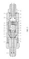
- FIG. 2 shows the assembled bidirectional check valve of FIG. 1 in which the valve is closed to prevent fluid flow in both forward and reverse directions;
- FIG. 3 shows the bidirectional check valve of FIGS. 1 and 2 in which the valve is open to permit fluid flow in a forward direction;
- FIG. 4 shows the bidirectional check valve of FIGS. 1 and 2 in which the valve is open to permit fluid flow in a reverse direction;
- FIG. 5 shows a conventional excavator vehicle which includes a hydraulic system
- FIG. 6 shows a hydraulic system of the excavator vehicle shown in FIG. 5 that is modified to incorporate the valve of FIGS. 1 - 4 .
- FIG. 1 shows an exploded view of a bidirectional check valve 100 , which is also shown in FIG. 2 with its components assembled, according to an embodiment of the invention.
- the bidirectional check valve includes a valve block 103 having an opening or port 116 at one end and another opening or port 117 at its opposite end. The openings 116 and 117 are connected by a passage 115 that extends throughout the valve block. Though two ports are shown, the bidirectional check valve may include additional ports.
- a poppet 104 is arranged within the passage 115 of the valve block or body 103 , such as by insertion through the opening 117 .
- the poppet is typically held in place by a portion of its outer wall 130 which contacts the passage wall 128 .
- One or more flutes or grooves 132 are formed in the outer wall 120 and, together with the wall 128 , define one or more channels 139 .
- the poppet also includes a passage 118 having an opening 119 at one end and an opening 120 at an opposite end.
- the outer wall 130 of the poppet also includes a tapered portion 134 near the opening 119 which is configured so that at least a portion of the tapered region may fit snugly against a narrowed portion 129 of the inner wall 128 of the valve block.
- a spring 105 is disposed within the passage 118 along a passage wall 133 of the poppet 104 and abuts a ledge 135 formed in the passage wall near the opening 119 of the poppet.
- a passage 122 is formed within the further poppet 106 and has an opening 124 at one end of the further poppet.
- One or more openings 123 are present in the outer wall of the further poppet 106 . The openings 123 open to an opposing end of the passage 122 which is adjacent to a tapered end 144 of the further poppet.
- a valve seat 108 is arranged within the passage 118 adjacent to the tapered end of the further poppet 106 .
- An opening 140 extends through the width of the valve seat 108 and includes a widened portion 144 at an end of the valve seat that is nearest the tapered end of the further poppet.
- the widened portion 144 of the opening and the tapered end of the further poppet together define a channel 148 between the valve seat 108 and openings 123 when the further poppet is displaced from the valve seat.
- a seal 107 such as an o-ring, is located in a groove or notch formed in the outer wall of the valve seat and prevents fluid leakage along the outer wall of the valve seat.
- a retaining ring 109 such as a snap ring, is seated within the passage 118 of the poppet 104 and is located adjacent to another end of the valve seat 108 to hold the valve seat in its position.
- a spring 110 is also provided and has a portion that is inserted into the passage 118 and abuts the retaining ring 109 . Another portion of the spring 110 extends beyond the poppet into the passage 115 of the valve block 103 and mates with an adapter 111 .
- the adapter is also disposed within the passage 115 of the valve block 103 .
- An opening 150 extends through the width of the adapter and includes a ledge 152 upon which the spring 110 is seated.
- a further retaining ring 112 is arranged within the passage 115 and is adjacent to the adapter 111 .
- an end adapter 111 is secured to the valve block 103 at opening 116 , such as by threads or other types of connections, to permit the valve block to be connected to a hydraulic line or other hydraulic leads, for example.
- a seal 102 which may be an o-ring, is provided between the end adapter 101 and the valve block 103 .
- Another end adapter 114 may be secured to the valve block 103 at opening 117 using threads or other types of connections, for example.
- Another seal 113 such as an o-ring, is provided between the end adapter 114 and the valve block 103 .
- FIG. 2 shows the bidirectional check valve 100 of the invention when the valve is closed in both directions to the passage of fluid.
- the valve 100 is closed in both directions under any of the following conditions: (1) when no fluid is present at both sides of the valve, (2) when no fluid is present at the opening 116 of the valve and the fluid pressure at the opening 117 is less than the force exerted by the spring 105 , (3) when no fluid is present at opening 117 and the fluid pressure at opening 116 is less than the force exerted by the spring 110 , and (4) when the fluid pressure on each side of the valve is less than the force exerted by springs 105 and 110 , respectively.
- the spring 110 drives the poppet 104 in the direction of opening 116 and secures part or all of the tapered end of the outer wall 130 of the poppet 104 against at least a part of the narrowed end 129 of the wall 128 of the passage 115 so that the flow of fluid from opening 116 into the channels 134 is cut off.
- the spring 105 drives the further poppet 106 in the direction of opening 117 and secures part or all of the tapered end of the outer wall of the further poppet against at least a part of the widened end of the opening in the valve seat 108 so that the flow of fluid from opening 117 into the openings 123 of the further poppet 106 is cut off.
- FIG. 3 depicts the bidirectional check valve 100 when the valve is open in one direction to permit the passage of fluid from the opening 116 to the opening 117 , namely when the fluid pressure at opening 116 is greater than the force exerted by the spring 110 .
- the force of the fluid drives the poppet 104 in the direction of opening 117 and moves the tapered end 134 of the outer wall of the poppet 104 away from the narrowed end 129 of the wall of the passage 115 which permits the flow of fluid from opening 116 into the channels 139 , past the end of the poppet 104 and through the opening 117 .
- the spring 105 holds the tapered end 144 of the outer wall of the further poppet 106 against the face of the widened end 142 of the opening in the valve seat 108 and prevents the flow of fluid in the opposite direction.
- FIG. 4 shows the bidirectional check valve 100 of the invention when the valve is open in the opposite direction to permit the passage of fluid from the opening 117 to the opening 116 , namely when the fluid pressure at opening 117 is greater than the force exerted by the spring 105 .
- the force of the fluid drives the further poppet 106 in the direction of opening 116 and moves the tapered end 144 of the further poppet away from the widened end 142 of the opening in the valve seat 108 which permits the flow of fluid from the opening 117 through opening 150 of the adapter 111 and opening 140 of the valve seat 108 , and into the channel 148 formed between the outer wall 146 of the further poppet and the wall 133 of the passage within the poppet.
- the fluid then flows through the openings 123 into the passage 122 within the further poppet and then through the opening 119 of the poppet to the opening 116 of the valve block.
- the spring 110 holds the tapered end of the outer wall 130 of the poppet 104 against the narrowed end 129 of the wall 128 of the passage 115 and blocks the flow of fluid in the opposite direction.
- the bidirectional check valve of the invention is a self-contained device that may be installed in a fluid line or conduit, such as in a fluid powered hydraulic system.
- the direction of fluid flow through the valve is reversible, as is the direction in which fluid flow is blocked.
- valve opens in a respective direction when the fluid pressure rises above a predetermined value.
- the pressure at which the valve opens or closes in a given direction may be determined by the choice of spring force for the spring that checks fluid flow in that direction.
- FIG. 5 illustrates an example of a conventional excavator vehicle which includes a hydraulic system 200 .
- Hydraulically driven boom cylinders 201 a , 201 b drive a boom 203 in an upward or downward direction.
- a hydraulically driven arm cylinder 205 drives an arm 207 which is pivotally connected to the boom 203 .
- Tongs 209 are coupled to the arm 207 and are driven by hydraulic motors 313 .
- the tongs may be opened or closed by an operator to grasp large objects, such as cut trees, logs or beams.
- FIG. 6 shows an example of a closed-loop hydraulic system which may be employed in the conventional excavator vehicle of FIG. 5 and which includes one or more of the bidirectional check valves of the invention.
- a hydraulic pump 303 pumps hydraulic fluid from a reservoir 301 through one or more supply lines.
- the pump 303 drives hydraulic fluid through a supply line 310 A via valve sections 307 to a rotator 309 .
- the fluid is returned to the reservoir 301 via a return line 310 B and a filter 317 .
- the pump 303 drives hydraulic fluid via the valve sections 307 and a supply line 312 A to further valve sections 311 and then to hydraulic motors 313 and/or hydraulic cylinders 315 .
- the fluid is then returned via a return line 312 B to the reservoir 301 .
- the bidirectional check valves close and prevent the sudden loss of hydraulic fluid from the rotator 309 , the hydraulic motors 313 and/or the hydraulic cylinders 315 , thereby avoiding a sudden and potentially catastrophic failure.
- the bidirectional check valve of the invention may also be employed in other applications that use a hydraulic system.
Abstract
A bidirectional check valve controls movement of fluid. A valve body has an opening, a further opening and a passage connecting the opening and the further opening. A poppet is disposed within the passage of the valve body, and a spring is coupled to the poppet. A further poppet is disposed within the passage formed in the first mentioned poppet, and a further spring is coupled to the poppet and to the further poppet. When fluid passing through the opening in the valve body exerts a force on the poppet that is greater than the spring force, the further portion of the outer surface of the poppet is directed away from the further portion of the wall of the passage and permits the fluid to flow from the opening in the valve body through a channel and to the further opening in the valve body. When fluid passing through the further opening in the valve body exerts a force on the further poppet that is greater than the further spring force, the further portion of the outer surface of the further poppet is directed away from the further opening in the valve body to open a further channel in the poppet and permit the fluid to flow from the further opening in the valve body through the further channel, at least one opening in the further poppet, a further passage in the further poppet, a further opening in the further poppet and an opening in the poppet to the opening of the valve body.
Description
This application claims the priority of U.S. Provisional Application Ser. No. 60/202,745, filed May 8, 2000.
The invention relates to mechanical valves and, more particularly, to check valves that prevent the movement of fluids in a hydraulic system when the pressure of the fluid is less than a predetermined value.
Conventional check valves permit liquids or gases to flow in only one direction. Such check valves are present in hydraulic systems, typically in mobile and fixed equipment, to control the flow path of fluids in the system. Check valves are also used in a variety of pumps to prevent the backward flow of liquids.
The hydraulic system is typically connected to other, auxiliary systems that may share a common fluid path with the hydraulic system. When a leak or hose failure occurs in the hydraulic system, fluid may also leak from the other systems that are connected to the hydraulic system and result in further fluid loss as well as cause the auxiliary systems to fail.
It is therefore desirable to prevent the loss of fluid from the auxiliary systems when a fluid is lost from the hydraulic system.
Further, fluid losses in the hydraulic system may be exacerbated by the auxiliary systems. When, for example, there is a back pressure from the auxiliary systems, pressurized fluid reservoirs or the like, the fluid pressure from the auxiliary systems aggravate any leaks present in the hydraulic system.
Also, when there is valve leakage from the auxiliary systems, fluid will also be lost from the hydraulic system.
Thus, there is also a need to automatically isolate the hydraulic system from the accessory systems to further fluid loss when there is a leak in either the hydraulic system or in an auxiliary system.
The present invention provides a bidirectional check valve that blocks the flow of fluid in a given direction when the fluid pressure in that direction falls below a predetermined value.
According to an aspect of the invention, a bidirectional check valve controls movement of fluid. A valve body has at least an opening and a further opening therein and has a passage connecting the opening and the further opening. A poppet is disposed within the passage of the valve body and is arranged such that at least a portion of an outer surface of the poppet and at least a portion of a wall of the passage of the valve body define at least one channel. The poppet has at least an opening therein in proximity to the opening in the valve body and has a passage connecting to the opening in the poppet. A spring is coupled to the poppet. The spring is arranged to drive the poppet in a direction such that when fluid passing through the opening in the valve body exerts a force on the poppet that is less than the spring force, a further portion of the outer surface of the poppet contacts a further portion of the passage wall of the valve body and prevents the fluid from flowing from the opening in the valve body into the channel. When the fluid exerts a force on the poppet that is greater than the spring force, the poppet is directed away from the further portion of the passage wall and permits the fluid to flow from the opening in the valve body through the channel and to the further opening in the valve body. A further poppet is disposed within the passage formed in the first mentioned poppet. The further spring is arranged such that at least a portion of an outer surface of the further poppet and at least a portion of a passage wall of the poppet define at least one further channel. The outer surface of the further poppet has at least an opening therein that connects to a passage formed within the further poppet. The passage within the further poppet connects to a further opening in the further poppet that is in proximity to the opening in the poppet. A further spring is coupled to the poppet and to the further poppet. The further spring is arranged to drive the further poppet in a further direction such that when fluid passing through the further opening in the valve body exerts a force on the further poppet that is less than the further spring force, a further portion of the outer surface of the further poppet blocks the further channel and prevents the fluid from flowing from the further opening in the valve body into the further channel. When the fluid exerts a force on the further poppet that is greater than the further spring force, the further portion of the outer surface of the further poppet is directed away from the further opening in the valve body to open the further channel and permit the fluid to flow from the further opening in the valve body through the further channel, the, at least, one opening in the further poppet, the further passage in the further poppet, the further opening in the further poppet and the opening in the poppet to the opening of the valve body.
According to another aspect of the invention, a hydraulic apparatus includes one or more supply lines, one or more return lines, a pump configured to drive fluid through the supply line at a supply pressure, and a flow component disposed between the supply line and the return line and providing a pressure differential in the fluid such that a return pressure in the return line is less than the supply pressure. The bidirectional check valve is disposed within the supply line and/or the return line.
Other features and advantages of the present invention will become apparent from the following detailed description of the invention with reference to the accompanying drawings.
The invention will now be described in greater detail in the following detailed description with reference to the drawings in which:
FIG. 1 shows an exploded view of a bidirectional check valve according to an embodiment of the invention;
FIG. 2 shows the assembled bidirectional check valve of FIG. 1 in which the valve is closed to prevent fluid flow in both forward and reverse directions;
FIG. 3 shows the bidirectional check valve of FIGS. 1 and 2 in which the valve is open to permit fluid flow in a forward direction;
FIG. 4 shows the bidirectional check valve of FIGS. 1 and 2 in which the valve is open to permit fluid flow in a reverse direction;
FIG. 5 shows a conventional excavator vehicle which includes a hydraulic system; and
FIG. 6 shows a hydraulic system of the excavator vehicle shown in FIG. 5 that is modified to incorporate the valve of FIGS. 1-4.
FIG. 1 shows an exploded view of a bidirectional check valve 100, which is also shown in FIG. 2 with its components assembled, according to an embodiment of the invention. The bidirectional check valve includes a valve block 103 having an opening or port 116 at one end and another opening or port 117 at its opposite end. The openings 116 and 117 are connected by a passage 115 that extends throughout the valve block. Though two ports are shown, the bidirectional check valve may include additional ports.
A poppet 104 is arranged within the passage 115 of the valve block or body 103, such as by insertion through the opening 117. The poppet is typically held in place by a portion of its outer wall 130 which contacts the passage wall 128. One or more flutes or grooves 132 are formed in the outer wall 120 and, together with the wall 128, define one or more channels 139. The poppet also includes a passage 118 having an opening 119 at one end and an opening 120 at an opposite end. The outer wall 130 of the poppet also includes a tapered portion 134 near the opening 119 which is configured so that at least a portion of the tapered region may fit snugly against a narrowed portion 129 of the inner wall 128 of the valve block.
A spring 105 is disposed within the passage 118 along a passage wall 133 of the poppet 104 and abuts a ledge 135 formed in the passage wall near the opening 119 of the poppet.
Also located within the passage 118, adjacent to the spring 105, is a further poppet 106. A passage 122 is formed within the further poppet 106 and has an opening 124 at one end of the further poppet. One or more openings 123 are present in the outer wall of the further poppet 106. The openings 123 open to an opposing end of the passage 122 which is adjacent to a tapered end 144 of the further poppet.
A valve seat 108 is arranged within the passage 118 adjacent to the tapered end of the further poppet 106. An opening 140 extends through the width of the valve seat 108 and includes a widened portion 144 at an end of the valve seat that is nearest the tapered end of the further poppet. The widened portion 144 of the opening and the tapered end of the further poppet together define a channel 148 between the valve seat 108 and openings 123 when the further poppet is displaced from the valve seat. A seal 107, such as an o-ring, is located in a groove or notch formed in the outer wall of the valve seat and prevents fluid leakage along the outer wall of the valve seat.
A retaining ring 109, such as a snap ring, is seated within the passage 118 of the poppet 104 and is located adjacent to another end of the valve seat 108 to hold the valve seat in its position. A spring 110 is also provided and has a portion that is inserted into the passage 118 and abuts the retaining ring 109. Another portion of the spring 110 extends beyond the poppet into the passage 115 of the valve block 103 and mates with an adapter 111. The adapter is also disposed within the passage 115 of the valve block 103. An opening 150 extends through the width of the adapter and includes a ledge 152 upon which the spring 110 is seated. A further retaining ring 112 is arranged within the passage 115 and is adjacent to the adapter 111.
Typically, an end adapter 111 is secured to the valve block 103 at opening 116, such as by threads or other types of connections, to permit the valve block to be connected to a hydraulic line or other hydraulic leads, for example. To prevent fluid leaks, a seal 102, which may be an o-ring, is provided between the end adapter 101 and the valve block 103.
Another end adapter 114 may be secured to the valve block 103 at opening 117 using threads or other types of connections, for example. Another seal 113, such as an o-ring, is provided between the end adapter 114 and the valve block 103.
FIG. 2 shows the bidirectional check valve 100 of the invention when the valve is closed in both directions to the passage of fluid. The valve 100 is closed in both directions under any of the following conditions: (1) when no fluid is present at both sides of the valve, (2) when no fluid is present at the opening 116 of the valve and the fluid pressure at the opening 117 is less than the force exerted by the spring 105, (3) when no fluid is present at opening 117 and the fluid pressure at opening 116 is less than the force exerted by the spring 110, and (4) when the fluid pressure on each side of the valve is less than the force exerted by springs 105 and 110, respectively.
In this configuration, the spring 110 drives the poppet 104 in the direction of opening 116 and secures part or all of the tapered end of the outer wall 130 of the poppet 104 against at least a part of the narrowed end 129 of the wall 128 of the passage 115 so that the flow of fluid from opening 116 into the channels 134 is cut off. Also, the spring 105 drives the further poppet 106 in the direction of opening 117 and secures part or all of the tapered end of the outer wall of the further poppet against at least a part of the widened end of the opening in the valve seat 108 so that the flow of fluid from opening 117 into the openings 123 of the further poppet 106 is cut off.
FIG. 3 depicts the bidirectional check valve 100 when the valve is open in one direction to permit the passage of fluid from the opening 116 to the opening 117, namely when the fluid pressure at opening 116 is greater than the force exerted by the spring 110.
The force of the fluid drives the poppet 104 in the direction of opening 117 and moves the tapered end 134 of the outer wall of the poppet 104 away from the narrowed end 129 of the wall of the passage 115 which permits the flow of fluid from opening 116 into the channels 139, past the end of the poppet 104 and through the opening 117.
The spring 105 holds the tapered end 144 of the outer wall of the further poppet 106 against the face of the widened end 142 of the opening in the valve seat 108 and prevents the flow of fluid in the opposite direction.
FIG. 4 shows the bidirectional check valve 100 of the invention when the valve is open in the opposite direction to permit the passage of fluid from the opening 117 to the opening 116, namely when the fluid pressure at opening 117 is greater than the force exerted by the spring 105.
The force of the fluid drives the further poppet 106 in the direction of opening 116 and moves the tapered end 144 of the further poppet away from the widened end 142 of the opening in the valve seat 108 which permits the flow of fluid from the opening 117 through opening 150 of the adapter 111 and opening 140 of the valve seat 108, and into the channel 148 formed between the outer wall 146 of the further poppet and the wall 133 of the passage within the poppet. The fluid then flows through the openings 123 into the passage 122 within the further poppet and then through the opening 119 of the poppet to the opening 116 of the valve block.
The spring 110 holds the tapered end of the outer wall 130 of the poppet 104 against the narrowed end 129 of the wall 128 of the passage 115 and blocks the flow of fluid in the opposite direction.
Advantageously, the bidirectional check valve of the invention is a self-contained device that may be installed in a fluid line or conduit, such as in a fluid powered hydraulic system. As a further advantage, the direction of fluid flow through the valve is reversible, as is the direction in which fluid flow is blocked.
An additional advantage is that the valve closes in a given direction whenever the fluid pressure decreases to less than a predetermined value. Thus, when a leak occurs in a hose or other component in a hydraulic system that causes a drop in fluid pressure, the valve blocks the flow of fluid from other portions of the hydraulic system and maintains fluid pressure in these portions. The valve also reduces the amount of fluid that leaks out, thereby reducing possible environmental contamination from the fluid.
Similarly, the valve opens in a respective direction when the fluid pressure rises above a predetermined value. The pressure at which the valve opens or closes in a given direction may be determined by the choice of spring force for the spring that checks fluid flow in that direction.
FIG. 5 illustrates an example of a conventional excavator vehicle which includes a hydraulic system 200. Hydraulically driven boom cylinders 201 a, 201 b drive a boom 203 in an upward or downward direction. A hydraulically driven arm cylinder 205 drives an arm 207 which is pivotally connected to the boom 203. Tongs 209 are coupled to the arm 207 and are driven by hydraulic motors 313. The tongs may be opened or closed by an operator to grasp large objects, such as cut trees, logs or beams.
FIG. 6 shows an example of a closed-loop hydraulic system which may be employed in the conventional excavator vehicle of FIG. 5 and which includes one or more of the bidirectional check valves of the invention. A hydraulic pump 303 pumps hydraulic fluid from a reservoir 301 through one or more supply lines. As an example, the pump 303 drives hydraulic fluid through a supply line 310A via valve sections 307 to a rotator 309. The fluid is returned to the reservoir 301 via a return line 310B and a filter 317. Alternatively, the pump 303 drives hydraulic fluid via the valve sections 307 and a supply line 312A to further valve sections 311 and then to hydraulic motors 313 and/or hydraulic cylinders 315. The fluid is then returned via a return line 312B to the reservoir 301.
The bidirectional check valves 305 of the invention may be installed in one or more of the supply lines to permit fluid to be delivered to the rotator 309 or to the valve sections 311 only when the pressure in the supply lines exceeds a predetermined value. The bidirectional check valves may also be installed in one or more of the return lines to permit fluid to be returned from the rotator 309 or from the valve sections 311 only when the pressure in the return lines exceed a predetermined value. Thus, hydraulic fluid is only supplied to the rotator 309, the hydraulic motors 313 and the hydraulic cylinders 315 when there is sufficient fluid pressure for their proper operation. Further, when a leak occurs in one or more of the supply or return lines, the bidirectional check valves close and prevent the sudden loss of hydraulic fluid from the rotator 309, the hydraulic motors 313 and/or the hydraulic cylinders 315, thereby avoiding a sudden and potentially catastrophic failure.
The bidirectional check valve of the invention may also be employed in other applications that use a hydraulic system.
Although the present invention has been described in relation to particular embodiments thereof, many other variations and modifications and other uses may become apparent to those skilled in the art. It is preferred, therefore, that the present invention be limited not by this specific disclosure herein, but only by the appended claims.
Claims (14)
1. A bidirectional check valve for controlling movement of fluid, said bidirectional check valve comprising:
a valve body having at least an opening and a further opening therein and having a passage connecting said opening and said further opening;
a poppet disposed within said passage of said valve body and arranged such that at least a portion of an outer surface of said poppet and at least a portion of a wall of said passage of said valve body define at least one channel; said poppet having at least an opening therein in proximity to said opening in said valve body and a passage connecting to said opening in said poppet;
a spring coupled to said poppet and arranged to drive said poppet in a direction such that when fluid passing through said opening in said valve body exerts a force on said poppet that is less than said spring force, a further portion of said outer surface of said poppet contacts a further portion of said passage wall of said valve body and prevents said fluid from flowing from said opening in said valve body into said channel, and when said fluid exerts a force on said poppet that is greater than said spring force, said poppet is directed away from said further portion of said passage wall and permits said fluid to flow from said opening in said valve body through said channel and to said further opening in said valve body;
a further poppet disposed within said passage formed in said first mentioned poppet and arranged such that at least a portion of an outer surface of said further poppet and at least a portion of a passage wall of said poppet define at least one further channel; said outer surface of said further poppet having at least an opening therein that connects to a passage formed within said further poppet; said passage within said further poppet connecting to a further opening in said further poppet that is in proximity to said opening in said poppet; and
a further spring coupled to said poppet and to said further poppet and arranged to drive said further poppet in a further direction such that when fluid passing through said further opening in said valve body exerts a force on said further poppet that is less than said further spring force, a further portion of said outer surface of said further poppet blocks said further channel and prevents said fluid from flowing from said further opening in said valve body into said further channel, and when said fluid exerts a force on said further poppet that is greater than said further spring force, said further portion of said outer surface of said further poppet is directed away from said further opening in said valve body to open said further channel and permit said fluid to flow from said further opening in said valve body through said further channel, said at least one opening in said further poppet, said further passage in said further poppet, said further opening in said further poppet and said opening in said poppet to said opening of said valve body.
2. The valve of claim 1 wherein said portion of said outer surface of said poppet includes at least one fluted portion.
3. The valve of claim 1 wherein said poppet includes a further opening therein in proximity to said further opening in said valve body; and said passage connects said opening and said further opening in said poppet.
4. The valve of claim 1 wherein said further portion of said outer surface of said poppet includes a tapered region, and said further portion of said passage wall of said valve body surrounds a narrowed portion of said passage.
5. The valve of claim 1 wherein said poppet includes an inwardly directed projection, and an end of said spring abuts said inwardly directed projection.
6. The valve of claim 5 further comprising a valve seat disposed in said passage of said poppet between said inwardly directed projection and said further poppet.
7. The valve of claim 6 wherein said further portion of said outer surface of said further poppet and said valve seat are configured such that when said fluid passing through said further opening in said valve body exerts a force on said further poppet that is less than said further spring force, said further portion of said outer surface of said further poppet contacts said valve seat.
8. The valve of claim 1 wherein said further portion of said outer surface of said further poppet comprises a tapered region.
9. The valve of claim 1 further comprising an adapter disposed in said passage of said valve body in proximity to said further opening in said valve body, and another end of said spring abuts a ledge formed in said adapter.
10. The valve of claim 1 wherein said passage wall of said poppet includes a ledge adjacent to said opening in said poppet, and an end of said further spring abuts said ledge.
11. The valve of claim 1 wherein said spring and said poppet are arranged such that when said fluid passing through said opening in said valve body exerts a force on said poppet that is less than said spring force, said poppet is driven toward said opening in said valve body, and when said fluid passing through said opening in said valve body exerts a force on said poppet that is greater than said spring force, said poppet is driven away from said opening in said valve body.
12. The valve of claim 1 wherein said further spring and said further poppet are arranged such that when said fluid passing through said further opening in said valve body exerts a force on said further poppet that is less than said further spring force, said further poppet is driven toward said further opening in said valve body, and when said fluid passing through said further opening in said valve body exerts a force on said further poppet that is greater than said further spring force, said further poppet is driven away from said further opening in said valve body.
13. A method of bidirectionally controlling movement of fluid, said method valve comprising the steps of:
providing a valve body having at least an opening and a further opening therein and having a passage connecting said opening and said further opening;
disposing a poppet within said passage of said valve body and arranging said poppet such that at least a portion of an outer surface of said poppet and at least a portion of a wall of said passage of said valve body define at least one channel; said poppet having at least an opening therein in proximity to said opening in said valve body and a passage connecting to said opening in said poppet;
coupling a spring to said poppet to drive said poppet in a direction such that when fluid passing through said opening in said valve body exerts a force on said poppet that is less than said spring force, a further portion of said outer surface of said poppet contacts a further portion of said passage wall of said valve body and prevents said fluid from flowing from said opening in said valve body into said channel, and when said fluid exerts a force on said poppet that is greater than said spring force, said poppet is directed away from said further portion of said passage wall and permits said fluid to flow from said opening in said valve body through said channel and to said further opening in said valve body;
disposing a further poppet within said passage formed in said first mentioned poppet and arranging said further poppet such that at least a portion of an outer surface of said further poppet and at least a portion of a passage wall of said poppet define at least one further channel; said outer surface of said further poppet having at least an opening therein that connects to a passage formed within said further poppet; said passage within said further poppet connecting to a further opening in said further poppet that is in proximity to said opening in said poppet; and
coupling a further spring to said poppet and to said further poppet to drive said further poppet in a further direction such that when fluid passing through said further opening in said valve body exerts a force on said further poppet that is less than said further spring force, a further portion of said outer surface of said further poppet blocks said further channel and prevents said fluid from flowing from said further opening in said valve body into said further channel, and when said fluid exerts a force on said further poppet that is greater than said further spring force, said further portion of said outer surface of said further poppet is directed away from said further opening in said valve body to open said further channel and permit said fluid to flow from said further opening in said valve body through said further channel, at least one said opening in said further poppet, said further passage in said further poppet, said further opening in said further poppet and said opening in said poppet to said opening of said valve body.
14. A hydraulic apparatus, comprising:
at least one supply line;
at least one return line;
a pump configured to drive fluid through said supply line at a supply pressure;
a flow component disposed between said supply line and said return line and providing a pressure differential in the fluid such that a fluid pressure in the return line is less than the supply pressure; and
a bidirectional check valve disposed within at least one of said supply line said return line;
said bidirectional check valve comprising:
a valve body having at least an opening and a further opening therein and having a passage connecting said opening and said further opening;
a poppet disposed within said passage of said valve body and arranged such that at least a portion of an outer surface of said poppet and at least a portion of a wall of said passage of said valve body define at least one channel; said poppet having at least an opening therein in proximity to said opening in said valve body and a passage connecting to said opening in said poppet;
a spring coupled to said poppet and arranged to drive said poppet in a direction such that when fluid passing through said opening in said valve body exerts a force on said poppet that is less than said spring force, a further portion of said outer surface of said poppet contacts a further portion of said passage wall of said valve body and prevents said fluid from flowing from said opening in said valve body into said channel, and when said fluid exerts a force on said poppet that is greater than said spring force, said poppet is directed away from said further portion of said passage wall and permits said fluid to flow from said opening in said valve body through said channel and to said further opening in said valve body;
a further poppet disposed within said passage formed in said first mentioned poppet and arranged such that at least a portion of an outer surface of said further poppet and at least a portion of a passage wall of said poppet define at least one further channel; said outer surface of said further poppet having at least an opening therein that connects to a passage formed within said further poppet, said passage within said further poppet connecting to a further opening in said further poppet that is in proximity to said opening in said poppet; and
a further spring coupled to said poppet and to said further poppet and arranged to drive said further poppet in a further direction such that when fluid passing through said further opening in said valve body exerts a force on said further poppet that is less than said further spring force, a further portion of said outer surface of said further poppet contacts a further portion of said passage wall of said poppet and prevents said fluid from flowing from said further opening in said valve body into said further channel, and when said fluid exerts a force on said further poppet that is greater than said further spring force, said further portion of said outer surface of said further poppet is directed away from said further portion of said wall of said poppet and permits said fluid to flow from said further opening in said valve body through said further channel, said at least one opening in said further poppet, said further passage in said further poppet, said further opening in said further poppet and said opening in said poppet to said opening of said valve body.
Priority Applications (8)
| Application Number | Priority Date | Filing Date | Title |
|---|---|---|---|
| US09/612,773 US6216729B1 (en) | 2000-05-08 | 2000-07-10 | Bidirectional check valve for hydraulic system |
| EP20000309952 EP1156244A3 (en) | 2000-05-08 | 2000-11-09 | Bidirectional check valve |
| KR1020000082465A KR20020005952A (en) | 2000-07-10 | 2000-12-27 | Bidirectional check valve for hydraulic system |
| JP2001015404A JP2001317641A (en) | 2000-05-08 | 2001-01-24 | Two-way check valve used in hydraulic system |
| CA002336265A CA2336265C (en) | 2000-05-08 | 2001-03-01 | Bidirectional check valve for hydraulic system |
| ARP010101899 AR028545A1 (en) | 2000-05-08 | 2001-04-24 | BIDIRECTIONAL VERIFICATION VALVE FOR HYDRAULIC PROVISION |
| BR0101633A BR0101633A (en) | 2000-05-08 | 2001-04-27 | Bidirectional check valve for hydraulic system |
| ID20010362D ID30109A (en) | 2000-05-08 | 2001-05-08 | VALVE CHECK TWO DIRECTIONS FOR HYDRAULIC SYSTEMS |
Applications Claiming Priority (2)
| Application Number | Priority Date | Filing Date | Title |
|---|---|---|---|
| US20274500P | 2000-05-08 | 2000-05-08 | |
| US09/612,773 US6216729B1 (en) | 2000-05-08 | 2000-07-10 | Bidirectional check valve for hydraulic system |
Publications (1)
| Publication Number | Publication Date |
|---|---|
| US6216729B1 true US6216729B1 (en) | 2001-04-17 |
Family
ID=26897993
Family Applications (1)
| Application Number | Title | Priority Date | Filing Date |
|---|---|---|---|
| US09/612,773 Expired - Fee Related US6216729B1 (en) | 2000-05-08 | 2000-07-10 | Bidirectional check valve for hydraulic system |
Country Status (7)
| Country | Link |
|---|---|
| US (1) | US6216729B1 (en) |
| EP (1) | EP1156244A3 (en) |
| JP (1) | JP2001317641A (en) |
| AR (1) | AR028545A1 (en) |
| BR (1) | BR0101633A (en) |
| CA (1) | CA2336265C (en) |
| ID (1) | ID30109A (en) |
Cited By (21)
| Publication number | Priority date | Publication date | Assignee | Title |
|---|---|---|---|---|
| KR20020005952A (en) * | 2000-07-10 | 2002-01-18 | 아더 엘. 슈와츠 | Bidirectional check valve for hydraulic system |
| WO2003087638A1 (en) * | 2002-04-15 | 2003-10-23 | Spill Check Ltd. | Bidirectional check valve |
| US6742540B2 (en) | 2002-06-28 | 2004-06-01 | Hyundai Motor Company | Two-way orifice check valve device for hydraulic circuit |
| US20050133451A1 (en) * | 2003-12-23 | 2005-06-23 | Ntz Nederland Bv | A full-flow microfiltration device and method for filtering fluids |
| US20060117946A1 (en) * | 2004-12-06 | 2006-06-08 | Mario Dubreuil | Hydraulic rotator and valve assembly |
| US20060289068A1 (en) * | 2005-06-28 | 2006-12-28 | Miller John J Jr | Check valve |
| US20070267068A1 (en) * | 2006-05-18 | 2007-11-22 | White Drive Products, Inc. | Shock valve for hydraulic device |
| US20080199339A1 (en) * | 2007-02-20 | 2008-08-21 | Richard Near | Safe backspin device |
| EP1719921A3 (en) * | 2005-05-02 | 2009-09-16 | FTE automotive GmbH | Valve assembly for dampening vibrations in a hydraulic drive comprising a master cylinder and a slave cylinder |
| NL1037579C2 (en) * | 2009-12-22 | 2011-06-23 | G Van Der Ziel Vastgoed B V | ANTI-LEVEL VALVE AND METHOD FOR ADJUSTING A LIQUID PUMP. |
| US20110226356A1 (en) * | 2008-12-02 | 2011-09-22 | Kosei Yamaguchi | Check valve |
| CN102537449A (en) * | 2011-12-07 | 2012-07-04 | 三一重型装备有限公司 | Bidirectional self-adaptive damping valve |
| US8240329B1 (en) | 2008-11-14 | 2012-08-14 | Robust Systems Solutions, LLC | Fluid control valve |
| US20130233397A1 (en) * | 2012-03-06 | 2013-09-12 | Benjamin McCloskey | Regurgitant Control Directional Flow Valve for Simulating Cardiovascular Hemodynamics |
| US20140216573A1 (en) * | 2011-09-01 | 2014-08-07 | Piolax, Inc. | Check valve |
| CN104047918A (en) * | 2014-07-17 | 2014-09-17 | 圣邦集团有限公司 | Duplex check valve |
| US20140326346A1 (en) * | 2011-12-07 | 2014-11-06 | Parker-Hannifin Corporation | Coupling |
| US9200648B2 (en) | 2011-01-24 | 2015-12-01 | Purdue Research Foundation | Fluid control valve systems, fluid systems equipped therewith, and methods of using |
| CN108561613A (en) * | 2018-05-13 | 2018-09-21 | 华东交通大学 | A kind of MR valve with rewind circuit |
| EP3480474A1 (en) * | 2017-10-26 | 2019-05-08 | Hamilton Sundstrand Corporation | Bi-directional inline check valve |
| CN110056666A (en) * | 2019-05-23 | 2019-07-26 | 李源 | A kind of bidirection press autocontrol valve and its working method |
Families Citing this family (2)
| Publication number | Priority date | Publication date | Assignee | Title |
|---|---|---|---|---|
| EP3308057B1 (en) * | 2015-06-10 | 2020-08-05 | Poclain Hydraulics Industrie | Pressure limiting device, in particular for a hydraulic assist system for vehicles |
| US9810336B2 (en) * | 2015-10-08 | 2017-11-07 | National Coupling Company | Subsea BOP control system with dual-action check valve |
Citations (3)
| Publication number | Priority date | Publication date | Assignee | Title |
|---|---|---|---|---|
| US4993921A (en) * | 1989-04-21 | 1991-02-19 | Vickers, Incorporated | Power transmission |
| US5048561A (en) * | 1989-04-21 | 1991-09-17 | Vickers, Incorporated | Bidirectional check valve |
| US6000417A (en) * | 1997-01-02 | 1999-12-14 | Jacobs; Richard R. | Bi-directional magnetically-operated check valve for high-purity applications |
Family Cites Families (7)
| Publication number | Priority date | Publication date | Assignee | Title |
|---|---|---|---|---|
| US2995148A (en) * | 1959-05-29 | 1961-08-08 | Novak Stanley | Poppet valve and mounting |
| US3153423A (en) * | 1962-05-16 | 1964-10-20 | Sealol | Two way check valve |
| US3127907A (en) * | 1962-09-18 | 1964-04-07 | Novak Stanley | Two-way poppet valve |
| GB1285733A (en) * | 1969-09-29 | 1972-08-16 | Lohtellier Ets | Improvements in automatic pressure equilibrating valves |
| FR2577903B1 (en) * | 1985-02-28 | 1987-11-20 | Thibonnet Bernard | BALANCING DEVICE FOR A FUEL TANK, ESPECIALLY FOR ROAD VEHICLES |
| US5183075A (en) * | 1986-04-12 | 1993-02-02 | Stein Guenter | Check valve |
| US4967791A (en) * | 1989-04-26 | 1990-11-06 | The Boeing Company | Pressure activated check valve |
-
2000
- 2000-07-10 US US09/612,773 patent/US6216729B1/en not_active Expired - Fee Related
- 2000-11-09 EP EP20000309952 patent/EP1156244A3/en not_active Withdrawn
-
2001
- 2001-01-24 JP JP2001015404A patent/JP2001317641A/en not_active Withdrawn
- 2001-03-01 CA CA002336265A patent/CA2336265C/en not_active Expired - Fee Related
- 2001-04-24 AR ARP010101899 patent/AR028545A1/en unknown
- 2001-04-27 BR BR0101633A patent/BR0101633A/en not_active Application Discontinuation
- 2001-05-08 ID ID20010362D patent/ID30109A/en unknown
Patent Citations (3)
| Publication number | Priority date | Publication date | Assignee | Title |
|---|---|---|---|---|
| US4993921A (en) * | 1989-04-21 | 1991-02-19 | Vickers, Incorporated | Power transmission |
| US5048561A (en) * | 1989-04-21 | 1991-09-17 | Vickers, Incorporated | Bidirectional check valve |
| US6000417A (en) * | 1997-01-02 | 1999-12-14 | Jacobs; Richard R. | Bi-directional magnetically-operated check valve for high-purity applications |
Cited By (34)
| Publication number | Priority date | Publication date | Assignee | Title |
|---|---|---|---|---|
| KR20020005952A (en) * | 2000-07-10 | 2002-01-18 | 아더 엘. 슈와츠 | Bidirectional check valve for hydraulic system |
| WO2003087638A1 (en) * | 2002-04-15 | 2003-10-23 | Spill Check Ltd. | Bidirectional check valve |
| US6742540B2 (en) | 2002-06-28 | 2004-06-01 | Hyundai Motor Company | Two-way orifice check valve device for hydraulic circuit |
| US20050133451A1 (en) * | 2003-12-23 | 2005-06-23 | Ntz Nederland Bv | A full-flow microfiltration device and method for filtering fluids |
| US20060117946A1 (en) * | 2004-12-06 | 2006-06-08 | Mario Dubreuil | Hydraulic rotator and valve assembly |
| US7152519B2 (en) | 2004-12-06 | 2006-12-26 | Rotobec Inc. | Hydraulic rotator and valve assembly |
| EP1719921A3 (en) * | 2005-05-02 | 2009-09-16 | FTE automotive GmbH | Valve assembly for dampening vibrations in a hydraulic drive comprising a master cylinder and a slave cylinder |
| WO2007002646A3 (en) * | 2005-06-28 | 2007-04-12 | Superb Ind Inc | Check valve |
| WO2007002646A2 (en) * | 2005-06-28 | 2007-01-04 | Superb Industries, Inc. | Check valve |
| US20060289068A1 (en) * | 2005-06-28 | 2006-12-28 | Miller John J Jr | Check valve |
| US7762276B2 (en) | 2005-06-28 | 2010-07-27 | Superb Industries, Inc. | Check valve |
| US20070267068A1 (en) * | 2006-05-18 | 2007-11-22 | White Drive Products, Inc. | Shock valve for hydraulic device |
| WO2007136998A3 (en) * | 2006-05-18 | 2008-07-24 | White Drive Products Inc | Shock valve for hydraulic device |
| US7513111B2 (en) * | 2006-05-18 | 2009-04-07 | White Drive Products, Inc. | Shock valve for hydraulic device |
| US20080199339A1 (en) * | 2007-02-20 | 2008-08-21 | Richard Near | Safe backspin device |
| US8240329B1 (en) | 2008-11-14 | 2012-08-14 | Robust Systems Solutions, LLC | Fluid control valve |
| US20110226356A1 (en) * | 2008-12-02 | 2011-09-22 | Kosei Yamaguchi | Check valve |
| US8561638B2 (en) * | 2008-12-02 | 2013-10-22 | Piolax Inc. | Check valve |
| NL1037579C2 (en) * | 2009-12-22 | 2011-06-23 | G Van Der Ziel Vastgoed B V | ANTI-LEVEL VALVE AND METHOD FOR ADJUSTING A LIQUID PUMP. |
| US9200648B2 (en) | 2011-01-24 | 2015-12-01 | Purdue Research Foundation | Fluid control valve systems, fluid systems equipped therewith, and methods of using |
| US9097356B2 (en) * | 2011-09-01 | 2015-08-04 | Piolax Inc. | Check valve |
| US20140216573A1 (en) * | 2011-09-01 | 2014-08-07 | Piolax, Inc. | Check valve |
| CN102537449B (en) * | 2011-12-07 | 2013-08-28 | 三一重型装备有限公司 | Bidirectional self-adaptive damping valve |
| US20140326346A1 (en) * | 2011-12-07 | 2014-11-06 | Parker-Hannifin Corporation | Coupling |
| CN102537449A (en) * | 2011-12-07 | 2012-07-04 | 三一重型装备有限公司 | Bidirectional self-adaptive damping valve |
| US20130233397A1 (en) * | 2012-03-06 | 2013-09-12 | Benjamin McCloskey | Regurgitant Control Directional Flow Valve for Simulating Cardiovascular Hemodynamics |
| CN104047918B (en) * | 2014-07-17 | 2016-02-24 | 圣邦集团有限公司 | Double linked one-way valve |
| CN104047918A (en) * | 2014-07-17 | 2014-09-17 | 圣邦集团有限公司 | Duplex check valve |
| EP3480474A1 (en) * | 2017-10-26 | 2019-05-08 | Hamilton Sundstrand Corporation | Bi-directional inline check valve |
| US10830365B2 (en) | 2017-10-26 | 2020-11-10 | Hamilton Sundstrand Corporation | Bi-directional inline check valve |
| CN108561613A (en) * | 2018-05-13 | 2018-09-21 | 华东交通大学 | A kind of MR valve with rewind circuit |
| CN108561613B (en) * | 2018-05-13 | 2023-10-13 | 华东交通大学 | Magnetorheological valve with quick return loop |
| CN110056666A (en) * | 2019-05-23 | 2019-07-26 | 李源 | A kind of bidirection press autocontrol valve and its working method |
| CN110056666B (en) * | 2019-05-23 | 2024-04-05 | 李源 | Automatic control valve for bidirectional pressure and working method thereof |
Also Published As
| Publication number | Publication date |
|---|---|
| CA2336265A1 (en) | 2001-11-08 |
| ID30109A (en) | 2001-11-08 |
| JP2001317641A (en) | 2001-11-16 |
| EP1156244A3 (en) | 2002-07-31 |
| CA2336265C (en) | 2004-05-04 |
| BR0101633A (en) | 2001-12-26 |
| EP1156244A2 (en) | 2001-11-21 |
| AR028545A1 (en) | 2003-05-14 |
Similar Documents
| Publication | Publication Date | Title |
|---|---|---|
| US6216729B1 (en) | Bidirectional check valve for hydraulic system | |
| CA2240929C (en) | Pilot solenoid control valve and hydraulic control system using same | |
| US6073652A (en) | Pilot solenoid control valve with integral pressure sensing transducer | |
| US4089169A (en) | Pressure actuated signal fluid control for load responsive systems | |
| US20170363217A1 (en) | Main Stage In-Line Pressure Control Cartridge with Optional Reverse Flow Function | |
| US4006667A (en) | Hydraulic control system for load supporting hydraulic motors | |
| SE510508C2 (en) | Device for controlling a hydraulic motor | |
| JPH05215102A (en) | Slide valve | |
| CA1201142A (en) | Log grapple device | |
| EP0187753B1 (en) | Brake release mechanism for vehicle towing | |
| EP0147392B1 (en) | Flow control valve assembly with quick response | |
| JP2002106507A (en) | Flow control device of hydraulic actuator | |
| US5749225A (en) | Hydraulic systems and valve assemblies | |
| WO2003087638A1 (en) | Bidirectional check valve | |
| US9518670B2 (en) | Main stage in-line pressure control cartridge with stepped retainer collar | |
| US5758683A (en) | On/off circuit for a hydraulic system | |
| WO2016205043A1 (en) | Main stage in-line pressure control cartridge with stepped retainer collar | |
| KR20020005952A (en) | Bidirectional check valve for hydraulic system | |
| JPH0429884B2 (en) | ||
| JP4614717B2 (en) | Directional control valve | |
| KR102216548B1 (en) | Check valve | |
| EP0299928B1 (en) | A priority flow control valve for hydraulic power circuits | |
| EP0396760A1 (en) | Operation valve device | |
| JPS603364Y2 (en) | Forklift hydraulic system | |
| CN115789000A (en) | Reversing link and hydraulic system with load holding |
Legal Events
| Date | Code | Title | Description |
|---|---|---|---|
| AS | Assignment |
Owner name: PARSONS & WHITTEMORE, INC., NEW YORK Free format text: ASSIGNMENT OF ASSIGNORS INTEREST;ASSIGNORS:HAMBLY, HUGH;THORNTON, BRIAN;REEL/FRAME:010928/0149 Effective date: 20000707 |
|
| RR | Request for reexamination filed |
Effective date: 20010703 |
|
| REMI | Maintenance fee reminder mailed | ||
| LAPS | Lapse for failure to pay maintenance fees | ||
| STCH | Information on status: patent discontinuation |
Free format text: PATENT EXPIRED DUE TO NONPAYMENT OF MAINTENANCE FEES UNDER 37 CFR 1.362 |
|
| FP | Lapsed due to failure to pay maintenance fee |
Effective date: 20050417 |
|
| FPB1 | Reexamination decision cancelled all claims |