US6210567B1 - Filtration device for tank water for aquarium fish - Google Patents
Filtration device for tank water for aquarium fish Download PDFInfo
- Publication number
- US6210567B1 US6210567B1 US09/254,393 US25439399A US6210567B1 US 6210567 B1 US6210567 B1 US 6210567B1 US 25439399 A US25439399 A US 25439399A US 6210567 B1 US6210567 B1 US 6210567B1
- Authority
- US
- United States
- Prior art keywords
- partitions
- cartridges
- casing
- cartridge
- lid
- Prior art date
- Legal status (The legal status is an assumption and is not a legal conclusion. Google has not performed a legal analysis and makes no representation as to the accuracy of the status listed.)
- Expired - Lifetime
Links
- XLYOFNOQVPJJNP-UHFFFAOYSA-N water Substances O XLYOFNOQVPJJNP-UHFFFAOYSA-N 0.000 title claims abstract description 62
- 238000001914 filtration Methods 0.000 title claims abstract description 52
- 241000251468 Actinopterygii Species 0.000 title abstract description 13
- 238000005192 partition Methods 0.000 claims abstract description 54
- 239000011148 porous material Substances 0.000 claims 2
- 241000894006 Bacteria Species 0.000 abstract description 5
- 230000009286 beneficial effect Effects 0.000 abstract description 2
- 239000002609 medium Substances 0.000 description 49
- CURLTUGMZLYLDI-UHFFFAOYSA-N Carbon dioxide Chemical compound O=C=O CURLTUGMZLYLDI-UHFFFAOYSA-N 0.000 description 6
- 238000004140 cleaning Methods 0.000 description 6
- 238000010586 diagram Methods 0.000 description 6
- 239000011324 bead Substances 0.000 description 3
- 229910002092 carbon dioxide Inorganic materials 0.000 description 3
- 239000001569 carbon dioxide Substances 0.000 description 3
- 239000000919 ceramic Substances 0.000 description 3
- 230000005465 channeling Effects 0.000 description 3
- 239000011491 glass wool Substances 0.000 description 3
- 230000012010 growth Effects 0.000 description 3
- QVGXLLKOCUKJST-UHFFFAOYSA-N atomic oxygen Chemical compound [O] QVGXLLKOCUKJST-UHFFFAOYSA-N 0.000 description 2
- 238000009434 installation Methods 0.000 description 2
- 229910052760 oxygen Inorganic materials 0.000 description 2
- 239000001301 oxygen Substances 0.000 description 2
- 230000008635 plant growth Effects 0.000 description 2
- 239000002699 waste material Substances 0.000 description 2
- 241000252229 Carassius auratus Species 0.000 description 1
- 229910002651 NO3 Inorganic materials 0.000 description 1
- NHNBFGGVMKEFGY-UHFFFAOYSA-N Nitrate Chemical compound [O-][N+]([O-])=O NHNBFGGVMKEFGY-UHFFFAOYSA-N 0.000 description 1
- 238000009825 accumulation Methods 0.000 description 1
- 230000002411 adverse Effects 0.000 description 1
- 239000003610 charcoal Substances 0.000 description 1
- 150000001875 compounds Chemical class 0.000 description 1
- 230000003247 decreasing effect Effects 0.000 description 1
- 239000012737 fresh medium Substances 0.000 description 1
- 239000013505 freshwater Substances 0.000 description 1
- 239000007789 gas Substances 0.000 description 1
- 239000011368 organic material Substances 0.000 description 1
- 239000004576 sand Substances 0.000 description 1
Images


Classifications
-
- A—HUMAN NECESSITIES
- A01—AGRICULTURE; FORESTRY; ANIMAL HUSBANDRY; HUNTING; TRAPPING; FISHING
- A01K—ANIMAL HUSBANDRY; AVICULTURE; APICULTURE; PISCICULTURE; FISHING; REARING OR BREEDING ANIMALS, NOT OTHERWISE PROVIDED FOR; NEW BREEDS OF ANIMALS
- A01K63/00—Receptacles for live fish, e.g. aquaria; Terraria
- A01K63/04—Arrangements for treating water specially adapted to receptacles for live fish
- A01K63/045—Filters for aquaria
Definitions
- This invention pertains to aquarium water filtration equipment with its main focus on smaller equipment size, maximum reduction of water to filter medium contact surface and ease of filer medium installation and replacement.
- FIG. 6 is an example of a conventional filtering device, commonly called the open system.
- Medium such as glass wool ( 21 ) and ceramic beads ( 22 ) are layered to form a filtration layer.
- Water in the tank ( 23 ) is siphoned by a pump ( 24 ) then passing through multiple holes (not shown) in the sprinkler head ( 25 ) and sprayed over the filtration layer.
- the larger debris is trapped by the glass wool ( 21 )
- the ceramic beads ( 22 ) function as biological filter (bacteria in the medium breaks down the organic material such as fish waste, decomposing plants matte, fish food, etc. into nitrate, a harmless compound). Then the filtered water is returned to the tank ( 23 ).
- the open system is designed to expose the filter surface for oxygen intake, but this allows the necessary element for plant growth, carbon dioxide, to escape and retards the growth of aquarium plants.
- FIG. 7 a schematic cross section diagram, illustrates another type of conventional filtration device commonly known as the sealed system.
- water from the tank ( 23 ) is siphoned up by a pump ( 24 ) and forced through a sealed cylinder or column ( 26 ) containing layers of several different types of filter medium ( 27 ).
- the purpose of this invention is to design a compact sealed forced water aquarium filtration equipment that is easy to remove isolated filter medium for cleaning and replacement thus providing the solution to the problems common to the conventional aquarium filtration device.
- This forced water aquarium filter system consists of a thin box shaped casing.
- the casing is divided vertically into several filtration chambers using partitions. Each of the multiple chambers holds readily removable cartridge of single filter medium.
- Water flow is designed so that the water from the tank is forced in through the top panel of the cartridge, down through the base panel, from the adjacent base panel up to the to panel in a down-up, up-down zigzag pattern.
- FIG. 1 sketch of aquarium filter system
- Example 1 partial cutaway, perspective view
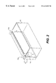
- FIG. 2 sketch of FIG. 1 filter system installed in aquarium: perspective view
- FIG. 3 diagram of water flow through the interior of the FIG. 1 filter system: cross section
- FIG. 4 sketch of aquarium filter system
- Example 2 partial cutaway, perspective view
- FIG. 5 diagram of water flow through the interior of the FIG. 4 filter system: cross section
- FIG. 6 sketch of an example of conventional filtration device: cross section
- FIG. 7 sketch of another example of a conventional filtration device: cross section
- FIG. 1 a sketch showing partially cutaway perspective view of the first example of the actual application of this invention illustrating the aquarium filter equipment and FIG. 2 is a sketch of the installed filter equipment as described in FIG. 1 viewed perspectively.
- This filter system consists of a two-part container ( 3 ) with an open thin box shaped casing ( 1 ) and a lid ( 2 ) to cover the opening.
- a two-part container ( 3 ) with an open thin box shaped casing ( 1 ) and a lid ( 2 ) to cover the opening.
- Within the casing are, for example six in this partial view sketch, vertical filtration chambers ( 4 a ⁇ 4 f ) separated by partitions ( 5 a ⁇ 5 e ) with three sides, base and two side edges, forming flush contact with the inside walls and the base of the casing.
- the chambers ( 4 a ⁇ 4 f ) are replaceable cartridges for individual filter medium ( 6 a ⁇ 6 f ), partial view.
- the partitions ( 5 a ⁇ 5 e ) for the chambers are positioned vertically in the casing ( 1 ) from the base to the lid ( 2 ) with some spacing between the top edge of the partition and the lid of the casing.
- Formed at the lower edge of the partitions 5 a , 5 c , 5 e are openings ( 17 ) to allow the water to circulate.
- Partitions 5 a , 5 c , 5 e are positioned higher than the partition 5 b and 5 d forming a flush contact with the lid ( 2 ). These each have a notched vent ( 13 ) at the upper edge to release the minute amount of carbon dioxide formed in the filtration chambers ( 4 a ⁇ 4 f ). Growth of helpful bacteria can be promoted by incorporating fine perforations (not illustrated) into the lower portions of the partitions 5 b and 5 d . This allows the oxygen rich water in the earlier stage chambers to seep into the latter chambers.
- the filter medium cartridge ( 6 a ) that fits inside the chambers is constructed of 4-side panels ( 8 ) and top ( 10 ) and base panel ( 11 ) with perforation ( 9 ).
- All other filter medium cartridges ( 6 b ⁇ 6 f ) are constructed similarly to the above cartridge ( 6 a ).
- this filtration equipment is suspended on the rear exterior of the tank.
- the intake tube ( 15 a ) with the siphon pump ( 14 ) on its end and the return tube ( 15 b ) are attached close to either ends of the casing lid ( 2 ). Suspending the filter equipment behind the tank eliminates unsightly obstructions and enhances the esthetic value of the aquarium.
- FIG. 3 is a cross section sketch to illustrate water flow through the system.
- pump ( 14 ) When pump ( 14 ) is activated, water in the tank ( 16 ) flows through the intake tube ( 15 a ) and enters the filtration system. Water entering the filtration system will first flow into the medium cartridge ( 6 a ) through the perforation ( 9 ) in the top panel ( 10 ). Water is filtered as it flows through the medium in the cartridge and exits through the perforation ( 9 ) then through the opening ( 17 ) in the partition ( 5 a ). Water that flowed through the opening ( 17 ) now enters the next chamber.
- the water is forced upwards through the medium in cartridge ( 6 b ) and out through the perforation ( 9 ) in the top panel ( 10 ), then into the next cartridge ( 6 c ).
- the water travels through the medium contained in cartridge ( 6 c ) as it gets filtered, then flow through the opening ( 17 ) in the partition ( 5 c ) and enters the next chamber ( 6 d ).
- Water will flow through the partitions ( 5 a ⁇ 5 e ) following the pattern in the direction of the arrow in vertical zigzag pattern as illustrated in FIG. 3 .
- the water reaches the last cartridge ( 6 f ), it is forced up through the perforation ( 9 ) in the top panel ( 10 ) and through the return tube ( 15 b ) back to the tank ( 16 ).
- This filtration system is designed so the vertical zigzag pattern of water flowing through medium cartridges ( 6 a ⁇ 6 b ) increases the distance of water traveling through the medium thus decreasing the necessary exposed surface area of medium. This makes it possible to reduce the quantity of filter medium needed therefore reducing the size and weight of the system without sacrificing the its capability.
- This filter system encourages the aquarium water plant growth by minimizing the escape of carbon dioxide into the atmosphere. When the filter system is in operation accumulation of debris will require replacement of the medium. In such case, lift the lid ( 2 ) and as shown in FIG. 1, remove the cartridge ( 6 ) by lifting it out from the filtration chamber ( 4 ) and replace it with a cartridge containing fresh medium.
- each medium is contained separately in the cartridge ( 6 a ⁇ 6 f ) replacement of specific medium is possible. Also this system allows the flexibility of selecting and arranging the filter medium based on the needs and type of fish kept in the aquarium.
- FIG. 4 and FIG. 5 Another example of the application of this invention can be described using FIG. 4 and FIG. 5 . To avoid unnecessary repetition of information, descriptions that are the same as that of Example 1 will be indicated as such and not repeated.
- FIG. 4 sketch of aquarium filter system
- Example 2 partially cutaway
- FIG. 5 diagram of water flow through the interior of the FIG. 4 filter system: cross section
- This filter system similar to the system above consists of a container ( 3 ) with casing ( 1 ) and lid ( 2 ), partitions ( 5 a ⁇ 5 e ), and cartridges for individual filter medium ( 6 a ⁇ 6 f ).
- the difference in this system from the previously described system is that the partitions 5 a , 5 c , and 5 e do not have the opening ( 17 ).
- the upper edges of the partitions ( 5 a ⁇ 5 e ) are positioned at the same level.
- the cartridge is constructed from side panel ( 8 ), perforated ( 9 ) top ( 10 ) and base ( 11 ) panels, a fixed partition ( 12 ) to divide the cartridge vertically in two equal sections.
- the cartridges ( 6 a ⁇ 6 f ) are inserted parallel to the partitions ( 5 a ⁇ 5 e ) into each of the filtration chambers ( 4 a ⁇ 4 f ).
- the cartridges' position are determined by the stoppers ( 7 ), when the lid is closed over the casing the lid will form a flush contact with the upper edge of the partitions ( 12 ) in the cartridges.
- water entering the filtration system will first flow into the medium cartridge ( 6 a ) through the perforation ( 9 ) in the top panel ( 10 ).
- Then repeats the pattern by traveling through the medium on the left side of the cartridge ( 6 b ), then right side of the cartridge and on to the next cartridge ( 6 c ).
- water forms a U-shaped passage through each cartridge ( 5 a ⁇ 5 e ) that are divided in half by partitions ( 12 ).
- FIG. 5 shows, water travels in vertical zigzag pattern throughout the filter system.
- the number of filtration chamber ( 4 ) or the filter medium cartridges ( 6 ) can be modified according to the size of the tank and the type of fish. It is not necessary to insert filter medium cartridges ( 6 ) in all filtration chambers ( 4 ). Also, if the top panel ( 10 ) or the base panel ( 11 ) were made to be removable and not fixed to the attached medium cartridge ( 6 ), it is possible to remove just the medium from the cartridge for cleaning and replacing. In such case, reuse of the cartridges can be made possible.
- the filtration system can be installed above or below the tank by selecting the appropriate length and shape of the in-tank tube ( 15 a ) and the return tube ( 15 b )
Landscapes
- Life Sciences & Earth Sciences (AREA)
- Environmental Sciences (AREA)
- Marine Sciences & Fisheries (AREA)
- Animal Husbandry (AREA)
- Biodiversity & Conservation Biology (AREA)
- Farming Of Fish And Shellfish (AREA)
Abstract
Description
Claims (8)
Applications Claiming Priority (3)
| Application Number | Priority Date | Filing Date | Title |
|---|---|---|---|
| JP8260205A JP2976067B2 (en) | 1996-09-09 | 1996-09-09 | Ornamental fish tank water filtration device |
| JP8/260205 | 1996-09-09 | ||
| PCT/JP1997/003025 WO1998009509A1 (en) | 1996-09-09 | 1997-08-29 | Filtration device for tank water for acquarium fish |
Publications (1)
| Publication Number | Publication Date |
|---|---|
| US6210567B1 true US6210567B1 (en) | 2001-04-03 |
Family
ID=17344807
Family Applications (1)
| Application Number | Title | Priority Date | Filing Date |
|---|---|---|---|
| US09/254,393 Expired - Lifetime US6210567B1 (en) | 1996-09-09 | 1997-08-29 | Filtration device for tank water for aquarium fish |
Country Status (10)
| Country | Link |
|---|---|
| US (1) | US6210567B1 (en) |
| EP (1) | EP1013167A4 (en) |
| JP (1) | JP2976067B2 (en) |
| KR (1) | KR20010029490A (en) |
| CN (1) | CN1081891C (en) |
| AU (1) | AU729001B2 (en) |
| CA (1) | CA2265637A1 (en) |
| HK (1) | HK1021924A1 (en) |
| TW (1) | TW355123B (en) |
| WO (1) | WO1998009509A1 (en) |
Cited By (21)
| Publication number | Priority date | Publication date | Assignee | Title |
|---|---|---|---|---|
| US6383372B1 (en) * | 2000-01-08 | 2002-05-07 | Michael H. Houck | Sequential flow filtration chamber for treatment of waste water and associated method |
| US20020064927A1 (en) * | 2000-11-30 | 2002-05-30 | Lee Won-Jae | Apparatus for forming strontium-tantalum-oxide thin film and a method thereof |
| US6475382B2 (en) * | 2000-12-19 | 2002-11-05 | Co2 Solution Inc. | Treatment unit for treating a fluid and method thereof |
| US6585888B2 (en) * | 2001-06-01 | 2003-07-01 | T.F.H. Publications, Inc. | Aquarium filter system with interchangeable filter cartridges |
| WO2006029481A2 (en) * | 2004-09-17 | 2006-03-23 | Cumminscorp Limited | Modular aquaculture system |
| US20060096901A1 (en) * | 2004-11-08 | 2006-05-11 | Carley Joseph C | Filter housing arrangement with cartridge guides |
| US20070039557A1 (en) * | 2003-05-14 | 2007-02-22 | Carlo Vaccari | Filtration apparatus for aquaria |
| US7208084B2 (en) | 2004-09-07 | 2007-04-24 | T.F.H. Publications, Inc. | Modular aquarium filter |
| US7378019B1 (en) * | 2003-11-19 | 2008-05-27 | Little Giant Pump Company | Filter assembly with vortex fluid distributor |
| US20080210612A1 (en) * | 2005-10-05 | 2008-09-04 | Jw Pet Company Inc. | Aquarium filter cartridge and filtration system |
| US20080217225A1 (en) * | 2003-10-09 | 2008-09-11 | Mag-Life Llc | Aquarium having improved filtration system with neutral buoyancy substrate, pump and sediment removal system |
| US7425274B1 (en) * | 2004-12-09 | 2008-09-16 | Leon Helfet | Aquarium filter unit |
| US20090045111A1 (en) * | 2007-08-15 | 2009-02-19 | Donald Barry Huehn | Filter with self-positioning cartridge arrangement |
| US8066965B2 (en) | 2002-09-27 | 2011-11-29 | Co2 Solution Inc. | Process for recycling carbon dioxide emissions from power plants into carbonated species |
| US8329460B2 (en) | 2001-07-13 | 2012-12-11 | CO2 Solutions, Inc. | Carbonic anhydrase bioreactor and process |
| US8513848B2 (en) | 2003-10-09 | 2013-08-20 | Mag Life, Llc | Aquarium having improved filtration system with neutral buoyancy substrate, pump and sediment removal system |
| WO2009075666A3 (en) * | 2007-11-30 | 2016-06-09 | Prismedical Corporation | Modular water purification and delivery system |
| GB2540678A (en) * | 2015-07-22 | 2017-01-25 | Attwell Moorhead David | Bioremediation system |
| DE102016005993A1 (en) * | 2016-05-18 | 2017-11-23 | Ursula Röttger | Cleaning device for water-bearing containers |
| CN113678773A (en) * | 2021-08-30 | 2021-11-23 | 武义七点智能科技有限公司 | Longitudinal lattice-drawing type filtering fish tank |
| US11457616B2 (en) * | 2019-02-27 | 2022-10-04 | Quabit, Inc. | Water purification system and filtration block |
Families Citing this family (22)
| Publication number | Priority date | Publication date | Assignee | Title |
|---|---|---|---|---|
| KR20030025517A (en) * | 2001-09-21 | 2003-03-29 | 최병규 | Clean device for fish tank of water |
| US6755981B2 (en) * | 2001-12-20 | 2004-06-29 | Kuniaki Terato | Aquarium cleaning system |
| WO2006083145A1 (en) * | 2005-02-05 | 2006-08-10 | Sharon Korea Item Company Limited | Foam filter for aquarium having function of purifying air and water |
| FR2889518B1 (en) * | 2005-08-02 | 2008-04-11 | Sarl Aquatique De La Moine Sar | SYSTEM FOR THE TREATMENT OF DOMESTIC WASTEWATER |
| CN2894269Y (en) * | 2005-12-02 | 2007-05-02 | 胡兴潮 | Aquatic animals externally-hung ultraviolet disinfecting filter |
| KR101028714B1 (en) * | 2008-12-30 | 2011-04-14 | 이재필 | The water-purifying device of the aquarium having changable the filter |
| EP2281452B1 (en) * | 2009-08-07 | 2013-10-02 | Askoll Holding S.r.l. | Filtering unit for an aquarium vessel including at least one removable filter cartridge |
| JP5593057B2 (en) * | 2009-11-02 | 2014-09-17 | ヤンマー株式会社 | Aquarium |
| KR101416489B1 (en) * | 2012-11-12 | 2014-07-10 | 심규운 | An aquarium including fitering-tank |
| KR101404144B1 (en) * | 2013-08-30 | 2014-06-11 | 서용섭 | Cleaning system for aquarium |
| WO2015107645A1 (en) * | 2014-01-16 | 2015-07-23 | Imtエンジニアリング株式会社 | Marine product farming device and artificial marine plant used in same |
| KR101631283B1 (en) | 2015-10-21 | 2016-06-16 | 이원석 | fish tank filtering equipment |
| TWI654931B (en) * | 2017-12-15 | 2019-04-01 | 黃錫泉 | Collective culture device |
| CN109275617A (en) * | 2018-11-16 | 2019-01-29 | 中国水产科学研究院淡水渔业研究中心 | A kind of aquaculture water dirt separation and water circulation utilization system |
| KR102181469B1 (en) * | 2018-11-22 | 2020-11-23 | 주식회사 네오엔비즈 | Apparatus for biofloc aquaculture system. |
| KR102388402B1 (en) * | 2019-11-13 | 2022-04-27 | (주)뉴월드트레이딩 | Crustacean Storage System |
| KR102203369B1 (en) * | 2020-08-25 | 2021-01-14 | 피길연 | Culturing apparatus for rearing shrimp having water circulation system |
| KR102311548B1 (en) * | 2020-11-17 | 2021-10-13 | 주식회사 수앤텍 | Filter tank and contaminant removal system comprising the same |
| JP7065541B1 (en) * | 2021-02-08 | 2022-05-12 | 株式会社斉藤製作所 | Aquarium stand, aquarium stand kit |
| KR102305694B1 (en) * | 2021-02-09 | 2021-09-28 | 유종호 | Low noise water tank device that does not require water exchange |
| KR102314518B1 (en) * | 2021-03-15 | 2021-10-20 | 주식회사 수앤텍 | Nitrate removal system and denitrification filter tank included in the same |
| CN114027249A (en) * | 2021-11-10 | 2022-02-11 | 浙江大学中原研究院 | Intelligent automatic fish tank water replenishing device and method |
Citations (22)
| Publication number | Priority date | Publication date | Assignee | Title |
|---|---|---|---|---|
| US119189A (en) * | 1871-09-19 | Improvement in filtering-cisterns | ||
| US1450770A (en) * | 1919-02-17 | 1923-04-03 | Phillip S Frick | Sanitary self-cleaning filter |
| US3669297A (en) * | 1970-06-03 | 1972-06-13 | Metaframe Corp | Automatic siphoning filtration device |
| JPS4880397A (en) | 1972-02-05 | 1973-10-27 | ||
| US3768652A (en) * | 1972-01-17 | 1973-10-30 | J Jardim | Er reconditioning unit for aquaria |
| US3768651A (en) * | 1971-09-22 | 1973-10-30 | W Streeter | Aquarium filter |
| JPS497098A (en) | 1972-02-24 | 1974-01-22 | ||
| US3892663A (en) * | 1972-08-01 | 1975-07-01 | Eheim Gunther | Home fish-tank filter construction |
| US3957634A (en) * | 1974-05-20 | 1976-05-18 | Orensten Henry E | Filtration means and method |
| US4067809A (en) * | 1975-06-12 | 1978-01-10 | Yukio Kato | Filtering system for fish-farming water |
| US4133760A (en) * | 1976-07-02 | 1979-01-09 | Yonekichi Ogawa | Knockdown type filtering device |
| JPS5415899A (en) | 1977-06-28 | 1979-02-06 | Kato Yukio | Sinkable filter instrument for fish breeding |
| US4220530A (en) * | 1979-05-29 | 1980-09-02 | Gabriele Raymond S | Fish tank filter |
| JPS5867514A (en) | 1981-10-19 | 1983-04-22 | Nippon Radiator Co Ltd | Automobile's air conditioner |
| JPS58128693A (en) | 1982-01-26 | 1983-08-01 | 松下電器産業株式会社 | High frequency heater |
| JPS58178869A (en) | 1982-04-13 | 1983-10-19 | Hanshin Electric Co Ltd | Ignition device for internal-combustion engine |
| JPS6039043A (en) | 1983-08-10 | 1985-02-28 | Hitachi Ltd | Centering device |
| JPS62129119A (en) | 1985-11-29 | 1987-06-11 | Flex I:Kk | Filter pack for water tank |
| JPS62282613A (en) | 1986-04-17 | 1987-12-08 | Kimiko Shima | Stair type filter tank |
| JPH0391764A (en) | 1989-09-05 | 1991-04-17 | Tomoegawa Paper Co Ltd | Toner for developing electrostatic charge image |
| JPH0415289A (en) | 1989-12-11 | 1992-01-20 | Kose Corp | Liquid crystal composition and cosmetic composition comprising the same |
| US5171438A (en) * | 1991-07-30 | 1992-12-15 | Korcz Robert L | Aquarium filtration system |
Family Cites Families (3)
| Publication number | Priority date | Publication date | Assignee | Title |
|---|---|---|---|---|
| JPS51161397U (en) * | 1975-06-17 | 1976-12-22 | ||
| JPS58128693U (en) * | 1982-02-25 | 1983-08-31 | 新日本コア株式会社 | Water purification device for aquarium |
| JPS58178869U (en) * | 1982-05-24 | 1983-11-30 | 田口 幸人 | Aquarium fish tank filtration device |
-
1996
- 1996-09-09 JP JP8260205A patent/JP2976067B2/en not_active Expired - Fee Related
-
1997
- 1997-08-29 CN CN97197776A patent/CN1081891C/en not_active Expired - Lifetime
- 1997-08-29 KR KR1019997001926A patent/KR20010029490A/en not_active Application Discontinuation
- 1997-08-29 AU AU40325/97A patent/AU729001B2/en not_active Ceased
- 1997-08-29 CA CA002265637A patent/CA2265637A1/en not_active Abandoned
- 1997-08-29 US US09/254,393 patent/US6210567B1/en not_active Expired - Lifetime
- 1997-08-29 WO PCT/JP1997/003025 patent/WO1998009509A1/en not_active Application Discontinuation
- 1997-08-29 EP EP97937843A patent/EP1013167A4/en not_active Withdrawn
- 1997-09-02 TW TW086112606A patent/TW355123B/en active
-
2000
- 2000-02-14 HK HK00100875A patent/HK1021924A1/en not_active IP Right Cessation
Patent Citations (22)
| Publication number | Priority date | Publication date | Assignee | Title |
|---|---|---|---|---|
| US119189A (en) * | 1871-09-19 | Improvement in filtering-cisterns | ||
| US1450770A (en) * | 1919-02-17 | 1923-04-03 | Phillip S Frick | Sanitary self-cleaning filter |
| US3669297A (en) * | 1970-06-03 | 1972-06-13 | Metaframe Corp | Automatic siphoning filtration device |
| US3768651A (en) * | 1971-09-22 | 1973-10-30 | W Streeter | Aquarium filter |
| US3768652A (en) * | 1972-01-17 | 1973-10-30 | J Jardim | Er reconditioning unit for aquaria |
| JPS4880397A (en) | 1972-02-05 | 1973-10-27 | ||
| JPS497098A (en) | 1972-02-24 | 1974-01-22 | ||
| US3892663A (en) * | 1972-08-01 | 1975-07-01 | Eheim Gunther | Home fish-tank filter construction |
| US3957634A (en) * | 1974-05-20 | 1976-05-18 | Orensten Henry E | Filtration means and method |
| US4067809A (en) * | 1975-06-12 | 1978-01-10 | Yukio Kato | Filtering system for fish-farming water |
| US4133760A (en) * | 1976-07-02 | 1979-01-09 | Yonekichi Ogawa | Knockdown type filtering device |
| JPS5415899A (en) | 1977-06-28 | 1979-02-06 | Kato Yukio | Sinkable filter instrument for fish breeding |
| US4220530A (en) * | 1979-05-29 | 1980-09-02 | Gabriele Raymond S | Fish tank filter |
| JPS5867514A (en) | 1981-10-19 | 1983-04-22 | Nippon Radiator Co Ltd | Automobile's air conditioner |
| JPS58128693A (en) | 1982-01-26 | 1983-08-01 | 松下電器産業株式会社 | High frequency heater |
| JPS58178869A (en) | 1982-04-13 | 1983-10-19 | Hanshin Electric Co Ltd | Ignition device for internal-combustion engine |
| JPS6039043A (en) | 1983-08-10 | 1985-02-28 | Hitachi Ltd | Centering device |
| JPS62129119A (en) | 1985-11-29 | 1987-06-11 | Flex I:Kk | Filter pack for water tank |
| JPS62282613A (en) | 1986-04-17 | 1987-12-08 | Kimiko Shima | Stair type filter tank |
| JPH0391764A (en) | 1989-09-05 | 1991-04-17 | Tomoegawa Paper Co Ltd | Toner for developing electrostatic charge image |
| JPH0415289A (en) | 1989-12-11 | 1992-01-20 | Kose Corp | Liquid crystal composition and cosmetic composition comprising the same |
| US5171438A (en) * | 1991-07-30 | 1992-12-15 | Korcz Robert L | Aquarium filtration system |
Cited By (35)
| Publication number | Priority date | Publication date | Assignee | Title |
|---|---|---|---|---|
| US6383372B1 (en) * | 2000-01-08 | 2002-05-07 | Michael H. Houck | Sequential flow filtration chamber for treatment of waste water and associated method |
| US20020064927A1 (en) * | 2000-11-30 | 2002-05-30 | Lee Won-Jae | Apparatus for forming strontium-tantalum-oxide thin film and a method thereof |
| US6475382B2 (en) * | 2000-12-19 | 2002-11-05 | Co2 Solution Inc. | Treatment unit for treating a fluid and method thereof |
| US6585888B2 (en) * | 2001-06-01 | 2003-07-01 | T.F.H. Publications, Inc. | Aquarium filter system with interchangeable filter cartridges |
| US8329458B2 (en) | 2001-07-13 | 2012-12-11 | Co2 Solutions Inc. | Carbonic anhydrase bioreactor and process for CO2 containing gas effluent treatment |
| US8329460B2 (en) | 2001-07-13 | 2012-12-11 | CO2 Solutions, Inc. | Carbonic anhydrase bioreactor and process |
| US8329459B2 (en) | 2001-07-13 | 2012-12-11 | Co2 Solutions Inc. | Carbonic anhydrase system and process for CO2 containing gas effluent treatment |
| US8066965B2 (en) | 2002-09-27 | 2011-11-29 | Co2 Solution Inc. | Process for recycling carbon dioxide emissions from power plants into carbonated species |
| US8277769B2 (en) | 2002-09-27 | 2012-10-02 | Co2 Solutions Inc. | Process for treating carbon dioxide containing gas |
| US8435479B2 (en) | 2002-09-27 | 2013-05-07 | Co2 Solutions Inc. | Process for treating carbon dioxide containing gas |
| US20070039557A1 (en) * | 2003-05-14 | 2007-02-22 | Carlo Vaccari | Filtration apparatus for aquaria |
| US7578262B2 (en) * | 2003-05-14 | 2009-08-25 | Ferplast Spa | Filtration apparatus for aquaria |
| US20080217225A1 (en) * | 2003-10-09 | 2008-09-11 | Mag-Life Llc | Aquarium having improved filtration system with neutral buoyancy substrate, pump and sediment removal system |
| US8033252B2 (en) * | 2003-10-09 | 2011-10-11 | Mag-Life Llc | Aquarium having improved filtration system with neutral buoyancy substrate, pump and sediment removal system |
| US8513848B2 (en) | 2003-10-09 | 2013-08-20 | Mag Life, Llc | Aquarium having improved filtration system with neutral buoyancy substrate, pump and sediment removal system |
| US7378019B1 (en) * | 2003-11-19 | 2008-05-27 | Little Giant Pump Company | Filter assembly with vortex fluid distributor |
| US7208084B2 (en) | 2004-09-07 | 2007-04-24 | T.F.H. Publications, Inc. | Modular aquarium filter |
| WO2006029481A3 (en) * | 2004-09-17 | 2008-02-21 | Cumminscorp Ltd | Modular aquaculture system |
| WO2006029481A2 (en) * | 2004-09-17 | 2006-03-23 | Cumminscorp Limited | Modular aquaculture system |
| US7252762B2 (en) * | 2004-11-08 | 2007-08-07 | Tetra Holding (Us), Inc. | Filter housing arrangement with cartridge guides |
| US20060096901A1 (en) * | 2004-11-08 | 2006-05-11 | Carley Joseph C | Filter housing arrangement with cartridge guides |
| US7425274B1 (en) * | 2004-12-09 | 2008-09-16 | Leon Helfet | Aquarium filter unit |
| US20080210612A1 (en) * | 2005-10-05 | 2008-09-04 | Jw Pet Company Inc. | Aquarium filter cartridge and filtration system |
| US7628913B2 (en) | 2005-10-05 | 2009-12-08 | J.W. Pet Company, Inc. | Aquarium filter cartridge and filtration system |
| US20090045111A1 (en) * | 2007-08-15 | 2009-02-19 | Donald Barry Huehn | Filter with self-positioning cartridge arrangement |
| US7651609B2 (en) * | 2007-08-15 | 2010-01-26 | Tetra Holding (Us), Inc. | Filter with self-positioning cartridge arrangement |
| US7927483B2 (en) | 2007-08-15 | 2011-04-19 | Tetra Holding (Us), Inc. | Filter with self-positioning cartridge arrangement |
| US20100101987A1 (en) * | 2007-08-15 | 2010-04-29 | Tetra Holding (Us), Inc. | Filter with self-positioning cartridge arrangement |
| WO2009075666A3 (en) * | 2007-11-30 | 2016-06-09 | Prismedical Corporation | Modular water purification and delivery system |
| GB2540678A (en) * | 2015-07-22 | 2017-01-25 | Attwell Moorhead David | Bioremediation system |
| GB2540678B (en) * | 2015-07-22 | 2022-06-08 | Atwell Moorhead David | Bioremediation system |
| DE102016005993A1 (en) * | 2016-05-18 | 2017-11-23 | Ursula Röttger | Cleaning device for water-bearing containers |
| DE102016005993B4 (en) * | 2016-05-18 | 2018-04-12 | Ursula Röttger | Cleaning device for water-bearing containers |
| US11457616B2 (en) * | 2019-02-27 | 2022-10-04 | Quabit, Inc. | Water purification system and filtration block |
| CN113678773A (en) * | 2021-08-30 | 2021-11-23 | 武义七点智能科技有限公司 | Longitudinal lattice-drawing type filtering fish tank |
Also Published As
| Publication number | Publication date |
|---|---|
| WO1998009509A1 (en) | 1998-03-12 |
| AU729001B2 (en) | 2001-01-25 |
| JP2976067B2 (en) | 1999-11-10 |
| AU4032597A (en) | 1998-03-26 |
| TW355123B (en) | 1999-04-01 |
| CN1081891C (en) | 2002-04-03 |
| KR20010029490A (en) | 2001-04-06 |
| CN1230095A (en) | 1999-09-29 |
| EP1013167A1 (en) | 2000-06-28 |
| CA2265637A1 (en) | 1998-03-12 |
| HK1021924A1 (en) | 2000-07-21 |
| EP1013167A4 (en) | 2002-04-17 |
| JPH1080237A (en) | 1998-03-31 |
Similar Documents
| Publication | Publication Date | Title |
|---|---|---|
| US6210567B1 (en) | Filtration device for tank water for aquarium fish | |
| US4067809A (en) | Filtering system for fish-farming water | |
| US5171438A (en) | Aquarium filtration system | |
| US5306421A (en) | Filtration system for a fish tank | |
| US5474673A (en) | Top mounted biological filtration system for an aquarium | |
| US4098230A (en) | Aquarium | |
| US5593584A (en) | Septic tank filter | |
| NL8601075A (en) | AQUARIUM TRAY, EQUIPPED WITH A WATER CLEANING SYSTEM; A PREFABRICATED SYSTEM OF CONNECTED PLATES, WHETHER OR NOT PLACES WITH OPENINGS, WHICH CAN BE BUILT INTO AN AQUARIUM CONTAINER FORMING THE WATER CLEANING SYSTEM, AND AN ASSEMBLY OF PLATES CONTAINING ONE OR MORE OF THE FITTLE AND OF THEM AND CONTAINING ANY MORE OF THEMET OF ANY HOUSING. | |
| WO2002056995A1 (en) | Water filter | |
| US5290436A (en) | Aquarium filter | |
| US3693798A (en) | Aquarium filter device | |
| US8303811B1 (en) | Aquarium filter element with removable insert | |
| JPH08117776A (en) | Method and apparatus for purifying waste water | |
| JP4032367B2 (en) | Water purification equipment | |
| JPH1118620A (en) | Water tank apparatus | |
| JP3930880B2 (en) | Circulation filtration aquaculture equipment | |
| JP3030425U (en) | Filtration device | |
| JP3653014B2 (en) | Water tank filter | |
| JP4103752B2 (en) | Aquarium water purification device | |
| JP3055182U (en) | Filtration water tank | |
| JPS58163415A (en) | Filter apparatus | |
| JP4145688B2 (en) | Upper filter | |
| JP2540760Y2 (en) | Live fish tank | |
| JPS59132913A (en) | Filter apparatus | |
| KR101871677B1 (en) | Reverse bottom filtering apparatus and aquarium using the same |
Legal Events
| Date | Code | Title | Description |
|---|---|---|---|
| STCF | Information on status: patent grant |
Free format text: PATENTED CASE |
|
| FEPP | Fee payment procedure |
Free format text: PAT HOLDER CLAIMS SMALL ENTITY STATUS, ENTITY STATUS SET TO SMALL (ORIGINAL EVENT CODE: LTOS); ENTITY STATUS OF PATENT OWNER: SMALL ENTITY |
|
| REFU | Refund |
Free format text: REFUND - SURCHARGE FOR LATE PAYMENT, LARGE ENTITY (ORIGINAL EVENT CODE: R1554); ENTITY STATUS OF PATENT OWNER: SMALL ENTITY Free format text: REFUND - PAYMENT OF MAINTENANCE FEE, 4TH YEAR, LARGE ENTITY (ORIGINAL EVENT CODE: R1551); ENTITY STATUS OF PATENT OWNER: SMALL ENTITY |
|
| REMI | Maintenance fee reminder mailed | ||
| FPAY | Fee payment |
Year of fee payment: 4 |
|
| SULP | Surcharge for late payment | ||
| FPAY | Fee payment |
Year of fee payment: 8 |
|
| SULP | Surcharge for late payment |
Year of fee payment: 7 |
|
| FPAY | Fee payment |
Year of fee payment: 12 |