US6209657B1 - Forward folding tillage implement - Google Patents
Forward folding tillage implement Download PDFInfo
- Publication number
- US6209657B1 US6209657B1 US09/348,995 US34899598A US6209657B1 US 6209657 B1 US6209657 B1 US 6209657B1 US 34899598 A US34899598 A US 34899598A US 6209657 B1 US6209657 B1 US 6209657B1
- Authority
- US
- United States
- Prior art keywords
- rockshaft
- frame
- tool
- tool gang
- gang frame
- Prior art date
- Legal status (The legal status is an assumption and is not a legal conclusion. Google has not performed a legal analysis and makes no representation as to the accuracy of the status listed.)
- Expired - Lifetime
Links
Images


Classifications
-
- A—HUMAN NECESSITIES
- A01—AGRICULTURE; FORESTRY; ANIMAL HUSBANDRY; HUNTING; TRAPPING; FISHING
- A01B—SOIL WORKING IN AGRICULTURE OR FORESTRY; PARTS, DETAILS, OR ACCESSORIES OF AGRICULTURAL MACHINES OR IMPLEMENTS, IN GENERAL
- A01B73/00—Means or arrangements to facilitate transportation of agricultural machines or implements, e.g. folding frames to reduce overall width
- A01B73/02—Folding frames
- A01B73/06—Folding frames foldable about a vertical axis
- A01B73/065—Folding frames foldable about a vertical axis to a position essentially forward of the axis, in relation to the direction of travel
-
- A—HUMAN NECESSITIES
- A01—AGRICULTURE; FORESTRY; ANIMAL HUSBANDRY; HUNTING; TRAPPING; FISHING
- A01B—SOIL WORKING IN AGRICULTURE OR FORESTRY; PARTS, DETAILS, OR ACCESSORIES OF AGRICULTURAL MACHINES OR IMPLEMENTS, IN GENERAL
- A01B73/00—Means or arrangements to facilitate transportation of agricultural machines or implements, e.g. folding frames to reduce overall width
- A01B73/02—Folding frames
Definitions
- the conventional method of folding tillage implements is by folding wing sections along forward aligned axes such that the wings are folded to a generally upright position.
- Double folding wing sections may have outer sections that fold inwardly and downwardly from the ends of inner wing sections in five section winged implements.
- the minimum implement width that can be achieved by such folding is limited by the width of the center section.
- road transport may still be somewhat restricted as these implements often exceed twenty feet or more in transport width.
- a tillage-packer combination for drill seeding requires the gang supporting tillage elements to be maintained parallel to the ground through a range of adjustable operating levels.
- the drawbar disclosed in Summach '809 raises or lowers the first attached gang of elements in a rotatable manner through its field and transport ranges of motion. A level manner of height adjustment is required for tillage elements.
- Another problem that must be overcome for compact folding is the avoidance of the packer elements of the second gang striking the tillage elements of the first gang when raised to the transport position. If compact folding is not required, then the downward rotation of the suspended second gang may be limited so as not to impact the elements of the first gang. But when compact folding is desired, the elements of the second gang are in direct alignment with the ground elements of the first gang so that alignment is achieved.
- An implement having a toolbar or frame to which a first tool gang is attached may also have a second tool gang attached to the rearward end of the first tool gang so both sets of gangs are drawn by the implement frame or toolbar for field operation.
- Such an implement avails itself for compact folding in which the first tool gang may be rotated to a general upright position and the second tool gang becomes suspended from the now upper end of the first gang.
- Such an implement is patented in U.S. Pat. No. 4,821,809 to Summach et al. According to the patent, the implement frame or toolbar may be folded for compact folded transport. This design works particularly well for harrow-packer combined implements.
- This invention provides an offset for the alignment of the second gang elements from the first gang ground elements so they do not impact when the implement is folded.
- a spiral guide is provided on the pivotal connection on which the second implement gang is attached to the first implement gang. When the implement is folded to transport position, the spiral guide shifts the second gang out of alignment with the first gang so their elements do not impact.
- a forwardly folding tillage implement that carries a number of ground engaging tools on a tool gang frame disposed to the rear of a carrier frame.
- a rockshaft is disposed between the carrier frame and the tool gang frame and is movable between four rotated positions about two axes of rotation.
- a control mechanism controls the relative angular position of the rockshaft.
- a support mechanism disposed rearwardly of the axes of rotation to support the rear of the tool gang frame above the ground in the field working position.
- An abutment member restrains the relative rotation between the rockshaft and the tool gang frame to fully support the tool gang frame on the rockshaft upon rotation of the rockshaft.
- FIG. 1 is a schematic side elevational view of the preferred embodiment of the farm implement in a first position.
- FIG. 2 is a schematic side elevational view of the preferred embodiment of the farm implement in a second position.
- FIG. 3 is a schematic side elevational view of the preferred embodiment of the farm implement in a third position.
- FIG. 4 is a schematic side elevational view of the preferred embodiment of the farm implement in a fourth position.
- FIG. 5 is a schematic plan view of the preferred embodiment of the farm implement in its fully extended working position.
- FIG. 5 a is a schematic plan view of the preferred embodiment of the farm implement with its two wings partially folded forward.
- FIG. 5 b is a schematic plan view of the preferred embodiment of the farm implement with its two wings fully folded forward.
- FIG. 6 is a schematic side elevational view of the preferred embodiment of the farm implement.
- FIG. 7 is a schematic side elevational view of the preferred embodiment shown in FIG. 1 showing the depth control in more detail.
- FIG. 8 corresponds to FIG. 2 and shows the depth control in the second rockshaft position.
- FIG. 9 is a schematic side elevational view depicting a rockshaft position intermediate the second and third rockshaft positions.
- FIG. 10 is a schematic partial plan view of the tool gang frame of the preferred embodiment in the position corresponding to FIG. 1 .
- FIG. 11 is an enlarged schematic detail plan view of the spiral guide of the preferred embodiment in the position shown in FIG. 10 .
- FIG. 12 is an enlarged schematic detail elevational view of the spiral guide of FIGS. 10 and 11.
- FIG. 13 is a schematic partial plan view of tool gang frame depicting the spiral guide of FIG. 10 in the third and fourth rockshaft positions.
- FIG. 14 is an enlarged schematic detail plan view of the spiral guide depicted in FIG. 13 .
- FIG. 15 is a schematic side elevational view of the tool gang frame depicted in FIGS. 13 and 14 including typical tool 5 raised to a transport position.
- FIG. 16 is an enlarged schematic detail elevational view of the preferred embodiment corresponding to FIG. 1 to show a spring pressure transfer of weight.
- FIG. 17 is similar to FIG. 2 and shows the spring pressure mechanism out of contact with the rockshaft.
- FIG. 18 is a schematic plan view of the tool gang frame showing the automatic locking devices of the preferred embodiment.
- FIG. 18 a is an enlarged schematic detail plan view of a first joint in the autolock mechanism positioned on the carrier frame as identified by the arrow referring to FIG. 18 .
- FIG. 18 b is an enlarged schematic detail plan view of a second joint in the autolock mechanism positioned on the carrier frame as identified by the arrow referred to in FIG. 18 .
- FIG. 19 is a partial schematic plan view of the central portion of the carrier frame depicting the autolock mechanism in a field operating position.
- FIG. 19 a is a partial schematic elevational view of the central portion of the carrier frame as an orthogonal projection of FIG. 19 .
- FIG. 19 b is an enlarged schematic detail elevational view of a portion of the autolock mechanism positioned on the carrier frame as identified by the arrow referring to FIG. 19 a.
- FIG. 20 is a schematic plan view of the tool gang frame folded forwardly.
- FIG. 20 a is an enlarged schematic detail plan view of the first joints in the autolock mechanism similar to that of FIG. 18 a positioned on the carrier frame as identified by the arrow referring to FIG. 20, but depicting the mechanism when locked in the transport position.
- FIG. 20 b is an orthogonal projection of the locked first joints of FIG. 20 a depicting an elevational view thereof.
- FIG. 20 c is an enlarged schematic detail plan view of the second joint similar to that of FIG. 18 b , but depicted in the locked transport position, as identified by the arrow referring to FIG. 20 .
- FIGS. 21 and 22 show the implement in the position shown in FIG. 3 including more detail of the caster wheel lock in the elevational view of FIG. 21 and in the rear elevational view of FIG. 22 .
- FIG. 23 shows the implement in the position depicted in FIG. 4 with the wheels fully castered into the transportation position.
- FIG. 23 a is a schematic enlarged detail view of the castor wheel lock shown in FIG. 23 .
- FIG. 23 b is a schematic side elevational view of FIGS. 23 and 23 a.
- FIG. 24 is a schematic side elevational view similar to FIG. 1 but additionally showing the angled wing axis.
- FIG. 24 a shows diagrammatically the angled wing axis angle of inclination.
- FIGS. 24 b and 24 c show a partial schematic plan view and a partial elevation of the joint between the inner and outer wings in the field working position.
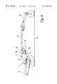
- FIG. 1 shows a side elevation of the implement in its lowermost or first position.
- Tool gang frame 3 is disposed parallel to the ground a and is freely rotatable about and supported front and back by first and second pivot axes 6 and 7 respectively.
- a plurality of ground working tools may be mounted on the tool gang frame for working at variable depths generally parallel to the surface of the ground a.
- a rockshaft 2 is mounted to carrier frame 1 for rotation about pivot axis 5 .
- the angular position of the rockshaft 2 is controlled by a hydraulic cylinder d shown fully retracted with the rockshaft 2 generally horizontal in FIG. 1.
- a flange 3 on tool gang frame 3 extends downward and provides pivotal support for tool gang frame 3 about axis 6 .
- a tool support arm 4 is pivotally attached at pivot axis 7 to support tool gang frame 3 at the rear and may carry an additional soil working tool c.
- FIG. 2 shows a side elevation of the implement upon partial extension of the hydraulic cylinder d to a second position at which rotation of the tool gang frame 3 about pivot axis 6 ceases when abutment f contacts tool gang frame 3 at abutment point g.
- the rear of tool gang frame 3 is supported by the control arm 4 .
- the working tools may be elevated above the ground.
- FIG. 3 shows a side elevation of the implement upon further extension of cylinder d to move the rockshaft to a third position.
- rotation of the tool gang frame 3 about second pivot axis 6 is restrained.
- frame 3 rotates in conjunction with rockshaft 2 about first pivot axis 5 , is supported on rockshaft 2 , and is free of the ground.
- tool gang frame roller j contacts curved track I mounted on carrier frame 1 .
- the carrier frame 1 is preferably arranged as a pair of wings symmetrical about the implement center line 308 for travel in direction A.
- Each of the 2 wings is pivotally attached to the central telescoping hitch 301 for motion about a vertical axis at 305 .
- the carrier frame 1 is supported on transversely spaced pairs of wheels b.
- the rockshaft 2 shown in FIGS. 1-4 is not shown on FIGS. 5-6 for simplicity.
- a plurality of tool gang frames 3 and support arms 4 are shown. Support tools c are represented schematically. Draft arms 303 connect each wing section as at pivotal attachment 304 on frame 1 to telescoping hitch 301 at pivot point 302 .
- the carrier frame 1 is folded forward symmetrically by extension of telescoping hitch 301 .
- the hitch 301 is extended in length in each successive figure.
- a pair of secondary draft or hitch members 309 is pivotally attached to hitch 301 at 302 and extends rearwardly towards secondary hitching point 307 .
- Mounted between members 309 and hitch point 307 are rear hitch members 313 which are pivotally connected between pivot points 312 and 314 for rotation about vertical axes.
- Pivot points 312 are also connected to support arms 310 extending from each hitch member to a respective frame section for pivotal movement as at 311 .
- a secondary hitch is provided to which another implement may be attached as at 307 for operation in the direction of travel A.
- the draft load of the second implement is supported on hitch members 309 and 313 along with support arms 310 which act to maintain hitch members 309 and 313 separated from the implement center line 308 .
- the distance B between pivots 305 and hitch point 307 is substantially shortened.
- the distance B is minimized, thereby bringing the second implement in close proximity to carrier frame 1 for stability in transport.
- FIG. 6 a schematic elevation of the preferred embodiment is shown in which the secondary hitch members 309 , 310 and 313 are above carrier frame 1 .
- FIGS. 7 through 9 the preferred embodiment will be described in relation to depth adjustment.
- FIGS. 7 and 8 correspond generally to FIGS. 1 and 2, respectively.
- FIG. 9 is a side elevation intermediate the second and third rockshaft positions.
- a depth control link 12 is pivotally attached at another point 13 on the rockshaft, offset from the tool gang pivot 6 .
- the depth control link is attached at end 14 to a first end of a depth control lever 8 .
- the lever is pivotally attached to the rear part of the tool gang frame 3 at an intermediate point between its ends.
- a roller 10 is attached to the lever's second end.
- the implement depth control 4 consists of an arm 21 which is pivotally attached at one end 7 to a rear part of the tool gang frame 3 and has ground engaging wheels 23 pivotally attached at its other end having a generally transverse axis 20 .
- roller 10 In the field position, roller 10 is in contact with the upper surface 22 of the support arm 21 and the support arm thereby supports the rearward part of the tool gang frame. This in part controls the depth of the tool gang frame as the ground wheels follow the surface of the ground.
- the tool gang frame 3 may pivot on attachment pivot 6 as ground wheels 23 and ground wheels 24 follow the slope of the ground.
- the tool gang is supported parallel to the ground between the frame ground wheels and depth gage ground wheels.
- a screw connects the depth control link to the depth control lever. The screw may be utilized to adjust the effective length of the depth control link for leveling the tool gang frame.
- Each tool gang frame may thereby be independently leveled.
- a turnbuckle or similar length adjusting means may be used in the depth control link.
- the rockshaft 2 of respective frame sections is rotated clockwise or counterclockwise as shown in the view in FIGS. 7 and 8 to respectively lower or raise the attached tool gang frame sections.
- the depth control link 12 is drawn forward relative to the tool gang frame 3 when the rockshaft is rotated counterclockwise to raise the tool gang frame.
- the depth control link causes the depth control lever 8 to rotate clockwise in the view of FIG. 8 and the roller on its second end bears down on the depth control support arm 4 , thereby causing rotation of the depth control in a clockwise direction.
- the attachment points of the linkage on the rockshaft and on the depth control lever are such that the rear depth control is rotated an amount causing an equal rise at the rear of the tool gang when the rockshaft raises the front of the tool gang as shown in FIGS. 7 and 8.
- the spiral guide 60 is made to have an axis generally concentric with the pivot 7 by which packer arm 21 is attached to tillage gang frame 3 .
- the packer arm has a spindle 71 extending its pivotally connected end on which a roller 70 is secured.
- the spiral guide 60 has a non-spiral surface 61 which the roller 70 follows when the implement is in the field position, and which restricts the sideways movement of the packer arm on the pivot shaft 7 , as shown in FIGS. 10-15. As the implement is folded to the transport position as shown in FIGS. 10-15, the roller 70 leaves the non-spiral surface 61 and follows the angled or spiral surface 62 .
- the roller 70 is limited by opposing spiral surface 63 .
- the spiral shape is such that the controlled movement causes a sideways or lateral offset 69 of the packer elements as the packer is suspended and rotates downwardly when being raised to the transport position.
- the spiral surfaces 62 , 63 control the roller movement and cause the packer to return to alignment with the tillage elements when lowered into the field position.
- the preferred embodiment may include a spring pressure mechanism to transfer weight to the tool gang frame 3 .
- the spring 50 may be pre-compressed by selectively shortening the available stroke of rod 51 , such as by a nut and tread on rod 50 . This provides of a large unsprung range of rotation between the first and second positions while providing the operator with additional adjustments.
- the tool gang frame 3 is depicted in its first position, the lowermost position, as viewed in FIG. 1 .
- Spring 50 acts between frame 3 and rod 51 to advantageously transfer weight to the frame.
- the spring is adjustable by lengthening or shortening the rod 53 .
- Arm 52 acts between rod 51 and rockshaft 2 and is pivotally attached to provide for abutment of rod 53 , as at 54 in FIG. 16 .
- rod 53 loses abutting contact as at 54 in FIG. 17 and rod 51 is fully retracted by spring 50 .
- automatic locking is provided by means of levers connected between the frame position control cylinders shown in FIG. 19 .
- the control cylinders have a limited degree of freedom of movement between the lever and the frame and the cylinders actuating movement.
- Interconnection of the lever with locks provides for automatic operation of the locks at the two extents of the cylinders' extension as shown so as to not interfere with extension and contraction of the cylinders and corresponding frame movement.
- the implement is shown with inner wings w 1 and outer wings w 2 symmetrically joined along the implement center line for pivotal relative motion between wings w 1 and w 2 about an axis generally in the direction of travel when in the field working position.
- FIG. 21 shows the implement in the position shown in FIG. 3, and FIG. 22 shows wheels b as item 24 for castering about a vertical axis at 25 with extending arm 26 in the field working position.
- Item f is referred to as 15 in FIGS. 21-23 b.
- FIG. 23 and in more detail in FIG. 23 a , the transport condition with wheels 24 fully castered about axis 25 and arm 26 locked in position by plate 27 is shown.
- FIG. 23 b shows the arm 26 in recess in plate 27 .
- FIG. 24 shows the implement in the position of FIG. 1 .
- Outer wing section w 2 is pivotally joined to inner wing section w 1 at forward and rearward points 51 and 52 respectively.
- angled wing axis 53 is depicted as inclined downward and forward in the direction of travel A by amount Dd.
- FIG. 24 b shows a partial plan view of inner wing section w 1 and outer wing section w 2 along with forward and rearward members w 1 a and w 1 b of inner wing w 1 .
- FIG. 24 c shows a partial rear elevation of FIG. 24 b.
Landscapes
- Life Sciences & Earth Sciences (AREA)
- Engineering & Computer Science (AREA)
- Mechanical Engineering (AREA)
- Soil Sciences (AREA)
- Environmental Sciences (AREA)
- Agricultural Machines (AREA)
Abstract
Description
Claims (17)
Priority Applications (5)
| Application Number | Priority Date | Filing Date | Title |
|---|---|---|---|
| US09/348,995 US6209657B1 (en) | 1998-03-12 | 1998-03-12 | Forward folding tillage implement |
| US09/737,800 US6371216B1 (en) | 1998-03-12 | 2000-12-18 | Tillage implement with spring pressure weight transfer mechanism |
| US09/737,798 US6336511B1 (en) | 1998-03-12 | 2000-12-18 | Tillage implement with automatic transport lock release |
| US09/737,801 US6269887B1 (en) | 1998-03-12 | 2000-12-18 | Forward folding tillage implement with secondary hitch |
| US09/737,799 US6321850B2 (en) | 1998-03-12 | 2000-12-18 | Tillage implement with offset cam for packers |
Applications Claiming Priority (1)
| Application Number | Priority Date | Filing Date | Title |
|---|---|---|---|
| US09/348,995 US6209657B1 (en) | 1998-03-12 | 1998-03-12 | Forward folding tillage implement |
Related Child Applications (4)
| Application Number | Title | Priority Date | Filing Date |
|---|---|---|---|
| US09/737,800 Division US6371216B1 (en) | 1998-03-12 | 2000-12-18 | Tillage implement with spring pressure weight transfer mechanism |
| US09/737,801 Division US6269887B1 (en) | 1998-03-12 | 2000-12-18 | Forward folding tillage implement with secondary hitch |
| US09/737,798 Division US6336511B1 (en) | 1998-03-12 | 2000-12-18 | Tillage implement with automatic transport lock release |
| US09/737,799 Division US6321850B2 (en) | 1998-03-12 | 2000-12-18 | Tillage implement with offset cam for packers |
Publications (1)
| Publication Number | Publication Date |
|---|---|
| US6209657B1 true US6209657B1 (en) | 2001-04-03 |
Family
ID=23370441
Family Applications (5)
| Application Number | Title | Priority Date | Filing Date |
|---|---|---|---|
| US09/348,995 Expired - Lifetime US6209657B1 (en) | 1998-03-12 | 1998-03-12 | Forward folding tillage implement |
| US09/737,800 Expired - Lifetime US6371216B1 (en) | 1998-03-12 | 2000-12-18 | Tillage implement with spring pressure weight transfer mechanism |
| US09/737,799 Expired - Lifetime US6321850B2 (en) | 1998-03-12 | 2000-12-18 | Tillage implement with offset cam for packers |
| US09/737,798 Expired - Lifetime US6336511B1 (en) | 1998-03-12 | 2000-12-18 | Tillage implement with automatic transport lock release |
| US09/737,801 Expired - Lifetime US6269887B1 (en) | 1998-03-12 | 2000-12-18 | Forward folding tillage implement with secondary hitch |
Family Applications After (4)
| Application Number | Title | Priority Date | Filing Date |
|---|---|---|---|
| US09/737,800 Expired - Lifetime US6371216B1 (en) | 1998-03-12 | 2000-12-18 | Tillage implement with spring pressure weight transfer mechanism |
| US09/737,799 Expired - Lifetime US6321850B2 (en) | 1998-03-12 | 2000-12-18 | Tillage implement with offset cam for packers |
| US09/737,798 Expired - Lifetime US6336511B1 (en) | 1998-03-12 | 2000-12-18 | Tillage implement with automatic transport lock release |
| US09/737,801 Expired - Lifetime US6269887B1 (en) | 1998-03-12 | 2000-12-18 | Forward folding tillage implement with secondary hitch |
Country Status (1)
| Country | Link |
|---|---|
| US (5) | US6209657B1 (en) |
Cited By (10)
| Publication number | Priority date | Publication date | Assignee | Title |
|---|---|---|---|---|
| US6371215B2 (en) | 1996-07-02 | 2002-04-16 | Flexi-Coil Ltd. | Locking rockshaft for tillage implements |
| US6374922B1 (en) * | 1997-05-21 | 2002-04-23 | Flexi-Coil Ltd. | Folding frame implement |
| US6663134B2 (en) | 2002-01-31 | 2003-12-16 | Case, Llc | Planter hitch apparatus |
| US20060090910A1 (en) * | 2004-07-20 | 2006-05-04 | Shane Houck | Implement convertible between use configuration and transport configuration |
| US20070163791A1 (en) * | 2006-01-17 | 2007-07-19 | Agco Corporation | Front folding agricultural implement frame with rearwardly telescoping tongue |
| US20080142234A1 (en) * | 2006-12-14 | 2008-06-19 | Friggstad Terrance A | Hydraulic control system having an upper depth stop valve with bypass |
| US20140262370A1 (en) * | 2013-03-15 | 2014-09-18 | Mcfarlane Manufacturing Co., Inc. | Universal custom agricultural field preparation implement |
| US10051775B2 (en) * | 2016-07-13 | 2018-08-21 | Cnh Industrial America Llc | Frame latch system |
| US10537052B2 (en) | 2017-04-18 | 2020-01-21 | Pillar Lasers Inc. | Multi-function hydraulic control of tool carrier assembly |
| WO2021168526A1 (en) * | 2020-02-26 | 2021-09-02 | Stara S/A. Indùstria De Implementos Agrícolas | Dispenser for soil improvers, fertilizers and seeds |
Families Citing this family (33)
| Publication number | Priority date | Publication date | Assignee | Title |
|---|---|---|---|---|
| US20030019642A1 (en) * | 2001-07-30 | 2003-01-30 | Moyna John P. | Hydraulic disc/harrow apparatus, system and method for using the same |
| US6691794B2 (en) | 2002-01-31 | 2004-02-17 | Case, Llc | Planter hitch locking and alignment apparatus |
| US20040188109A1 (en) * | 2002-02-08 | 2004-09-30 | Domries Bernard O. | Road-legal disc harrow |
| US6606956B1 (en) | 2002-03-04 | 2003-08-19 | Case, Llc | Planter coulter apparatus with mechanical overload protection |
| US6691629B2 (en) | 2002-03-04 | 2004-02-17 | Case, Llc | Planter coulter apparatus with hydraulic overload protection |
| US6679339B1 (en) * | 2002-12-19 | 2004-01-20 | Deere & Company | Implement lift and level system with a front mounted direct coupled rockshaft |
| US7543657B2 (en) * | 2004-08-25 | 2009-06-09 | Cnh Canada, Ltd. | Tillage apparatus having flexible frame and weight distribution system |
| US7182146B2 (en) * | 2004-09-01 | 2007-02-27 | Cnh Canada, Ltd. | Assembly for and method of constraining a flexible line of an agricultural implement |
| US7575066B2 (en) * | 2004-09-28 | 2009-08-18 | Environmental Tillage Systems, Inc. | Zone tillage tool and method |
| US7429003B2 (en) * | 2005-04-01 | 2008-09-30 | Cnh Canada, Ltd. | Spray boom suspension lock assembly |
| US7581597B2 (en) * | 2006-04-14 | 2009-09-01 | Cnh Canada, Ltd. | System for and method of moving an agricultural implement between a folded, inoperative position and an extended, operative position |
| US7513316B2 (en) * | 2006-09-15 | 2009-04-07 | Deere & Company | Implement rear hitch height and attitude control |
| US7849933B2 (en) * | 2007-10-19 | 2010-12-14 | Kuhn North America, Inc. | Bifold transport lock |
| US7854273B2 (en) | 2008-10-24 | 2010-12-21 | Cnh Canada, Ltd. | Agricultural implement having folding draft links |
| US8235133B2 (en) * | 2008-10-24 | 2012-08-07 | Cnh Canada, Ltd. | Agricultural implement having wheels that caster |
| US8141652B2 (en) * | 2008-11-21 | 2012-03-27 | Cnh America Llc | Implement frame with front folding wings and transport wheels |
| US7921932B2 (en) * | 2008-11-21 | 2011-04-12 | Cnh America Llc | Implement frame with front folding wings and transport wheels |
| US20100126743A1 (en) * | 2008-11-21 | 2010-05-27 | Cnh America Llc | Implement frame with front folding wings and transport wheels |
| US8636078B2 (en) | 2010-05-28 | 2014-01-28 | Cnh Canada, Ltd. | Mechanically controlled hydraulic system for an agricultural implement |
| ITUD20110208A1 (en) * | 2011-12-21 | 2013-06-22 | Tonutti Wolagri S P A Con Socio Un Ico | RAKE |
| CA2784575C (en) * | 2012-08-01 | 2015-04-14 | Bourgault Industries Ltd. | Rear folding toolbar implement |
| WO2014056077A1 (en) * | 2012-10-10 | 2014-04-17 | Scott Degelman | Cultivator |
| US9220188B2 (en) | 2013-08-19 | 2015-12-29 | Forage Innovations B.V. | Individually articulating automatic transport locks for folding implements |
| US9622400B2 (en) * | 2013-11-13 | 2017-04-18 | Cnh Industrial America Llc | Agricultural tillage implement wheel control |
| US9439340B2 (en) | 2013-11-13 | 2016-09-13 | Cnh Industrial America Llc | Frame configuration for an agricultural tillage implement |
| RU2544630C1 (en) * | 2013-11-25 | 2015-03-20 | Государственное научное учреждение Всероссийский научно-исследовательский институт механизации сельского хозяйства Российской академии сельскохозяйственных наук (ГНУ ВИМ Россельхозакадемии) | Mounted combined machine |
| US10299423B2 (en) | 2013-12-11 | 2019-05-28 | Cnh Industrial Canada, Ltd. | Computer controlled hydraulic bleed sequence |
| US10028423B2 (en) | 2013-12-11 | 2018-07-24 | Cnh Industrial America Llc | Tillage electro-hydraulic design and layout on fold sequence of fold machine |
| US9549496B2 (en) | 2013-12-11 | 2017-01-24 | Cnh Industrial America Llc | Tillage implement with foldable frame |
| US10021822B2 (en) | 2015-06-30 | 2018-07-17 | Cnh Industrial America Llc | Mounted implement weight transfer |
| US10798865B2 (en) | 2016-01-19 | 2020-10-13 | Fast Global Solutions Inc. | Agricultural implement with lift assist and uplift capability |
| CA2964431A1 (en) | 2017-04-18 | 2018-10-18 | Pillar Lasers Inc. | Implement with forward folding wing frames |
| US12016257B2 (en) | 2020-02-19 | 2024-06-25 | Sabanto, Inc. | Methods for detecting and clearing debris from planter gauge wheels, closing wheels and seed tubes |
Citations (8)
| Publication number | Priority date | Publication date | Assignee | Title |
|---|---|---|---|---|
| US2882979A (en) | 1954-07-22 | 1959-04-21 | Atlas Scraper And Engineering | Combination two-way plow and tool carrier |
| GB908625A (en) | 1960-04-11 | 1962-10-24 | Int Harvester Co | Improvements in or relating to tractor-implement combinations |
| US3106254A (en) * | 1961-10-23 | 1963-10-08 | Clark Mfg Company | Implement hitch for tractors |
| GB1037884A (en) | 1964-06-09 | 1966-08-03 | Ernest Doe And Sons Ltd | Improvements relating to means for mounting agricultural implements |
| AU1017166A (en) | 1967-08-25 | 1967-02-27 | HILARY MARCUS KOPKE, ERNA LINA KOPKE, PAULINE ANNE KOPKE and WAYNE HILARY KOPKE | Improved depth and angle control for cultivating implements |
| US4650006A (en) | 1983-07-13 | 1987-03-17 | Reimann Harold J | Auxiliary mounting device for cultivating implements |
| US4821809A (en) | 1979-08-17 | 1989-04-18 | Flexi-Coil Limited | Multiple section drawbar |
| US5143160A (en) * | 1991-03-22 | 1992-09-01 | May R Elwin | Chain harrow carts |
Family Cites Families (17)
| Publication number | Priority date | Publication date | Assignee | Title |
|---|---|---|---|---|
| US3333645A (en) | 1964-12-23 | 1967-08-01 | Elmer A Gustafson | Multiple purpose drawbar |
| US4042044A (en) | 1976-04-12 | 1977-08-16 | Deere & Company | Rear folding implement |
| US4137852A (en) * | 1976-09-03 | 1979-02-06 | Deere & Company | Forwardly foldable toolbar |
| US4418762A (en) | 1981-07-20 | 1983-12-06 | Western Manufacturing Company, Inc. | Balanced implement transport vehicle |
| US4496004A (en) | 1982-04-30 | 1985-01-29 | International Harvester Co. | Rearwardly folding agricultural implement |
| US4625345A (en) * | 1985-03-26 | 1986-12-02 | Wood Lorin A | Automated sofa bed |
| US4813489A (en) | 1987-12-21 | 1989-03-21 | Morris Rod-Weeder Co., Ltd. | Foldable packer harrow implement |
| US5158145A (en) | 1991-07-30 | 1992-10-27 | John Karchewski | Cultivator |
| US5163518A (en) * | 1991-08-21 | 1992-11-17 | Deere & Company | Down force adjustment and lift for an opener supported from a frame by lift arms |
| US5372540A (en) * | 1993-07-13 | 1994-12-13 | The Laitram Corporation | Robot cutting system |
| CA2132128C (en) | 1994-09-15 | 1996-11-26 | Charles Balmer | Frame for agricultural cultivator |
| US5641026A (en) | 1994-09-16 | 1997-06-24 | Balmer; Charles | Frame for agricultural cultivator |
| US5802995A (en) * | 1995-02-06 | 1998-09-08 | Baugher; Roger Dale | Planting unit |
| US5746566A (en) * | 1995-04-26 | 1998-05-05 | Design Systems, Inc. | Apparatus for a moving workpiece |
| US5727638A (en) * | 1996-08-01 | 1998-03-17 | Deere & Company | Down pressure system with free float extension |
| US6189465B1 (en) | 1998-11-12 | 2001-02-20 | Flexi-Coil Ltd. | Field marker control system for agricultural planters |
| US5992535A (en) * | 1999-02-03 | 1999-11-30 | Deere & Company | Dual acting implement leveling system with transport stabilization |
-
1998
- 1998-03-12 US US09/348,995 patent/US6209657B1/en not_active Expired - Lifetime
-
2000
- 2000-12-18 US US09/737,800 patent/US6371216B1/en not_active Expired - Lifetime
- 2000-12-18 US US09/737,799 patent/US6321850B2/en not_active Expired - Lifetime
- 2000-12-18 US US09/737,798 patent/US6336511B1/en not_active Expired - Lifetime
- 2000-12-18 US US09/737,801 patent/US6269887B1/en not_active Expired - Lifetime
Patent Citations (8)
| Publication number | Priority date | Publication date | Assignee | Title |
|---|---|---|---|---|
| US2882979A (en) | 1954-07-22 | 1959-04-21 | Atlas Scraper And Engineering | Combination two-way plow and tool carrier |
| GB908625A (en) | 1960-04-11 | 1962-10-24 | Int Harvester Co | Improvements in or relating to tractor-implement combinations |
| US3106254A (en) * | 1961-10-23 | 1963-10-08 | Clark Mfg Company | Implement hitch for tractors |
| GB1037884A (en) | 1964-06-09 | 1966-08-03 | Ernest Doe And Sons Ltd | Improvements relating to means for mounting agricultural implements |
| AU1017166A (en) | 1967-08-25 | 1967-02-27 | HILARY MARCUS KOPKE, ERNA LINA KOPKE, PAULINE ANNE KOPKE and WAYNE HILARY KOPKE | Improved depth and angle control for cultivating implements |
| US4821809A (en) | 1979-08-17 | 1989-04-18 | Flexi-Coil Limited | Multiple section drawbar |
| US4650006A (en) | 1983-07-13 | 1987-03-17 | Reimann Harold J | Auxiliary mounting device for cultivating implements |
| US5143160A (en) * | 1991-03-22 | 1992-09-01 | May R Elwin | Chain harrow carts |
Cited By (13)
| Publication number | Priority date | Publication date | Assignee | Title |
|---|---|---|---|---|
| US6371215B2 (en) | 1996-07-02 | 2002-04-16 | Flexi-Coil Ltd. | Locking rockshaft for tillage implements |
| US6374922B1 (en) * | 1997-05-21 | 2002-04-23 | Flexi-Coil Ltd. | Folding frame implement |
| US6663134B2 (en) | 2002-01-31 | 2003-12-16 | Case, Llc | Planter hitch apparatus |
| US20060090910A1 (en) * | 2004-07-20 | 2006-05-04 | Shane Houck | Implement convertible between use configuration and transport configuration |
| US20070163791A1 (en) * | 2006-01-17 | 2007-07-19 | Agco Corporation | Front folding agricultural implement frame with rearwardly telescoping tongue |
| US8127861B2 (en) | 2006-01-17 | 2012-03-06 | Agco Corporation | Front folding agricultural implement frame with rearwardly telescoping tongue |
| US7540332B2 (en) * | 2006-12-14 | 2009-06-02 | Cnh Canada, Ltd. | Hydraulic control system having an upper depth stop valve with bypass |
| US20080142234A1 (en) * | 2006-12-14 | 2008-06-19 | Friggstad Terrance A | Hydraulic control system having an upper depth stop valve with bypass |
| US20140262370A1 (en) * | 2013-03-15 | 2014-09-18 | Mcfarlane Manufacturing Co., Inc. | Universal custom agricultural field preparation implement |
| US9474197B2 (en) * | 2013-03-15 | 2016-10-25 | Mcfarlane Manufacturing Co., Inc. | Universal custom agricultural field preparation implement |
| US10051775B2 (en) * | 2016-07-13 | 2018-08-21 | Cnh Industrial America Llc | Frame latch system |
| US10537052B2 (en) | 2017-04-18 | 2020-01-21 | Pillar Lasers Inc. | Multi-function hydraulic control of tool carrier assembly |
| WO2021168526A1 (en) * | 2020-02-26 | 2021-09-02 | Stara S/A. Indùstria De Implementos Agrícolas | Dispenser for soil improvers, fertilizers and seeds |
Also Published As
| Publication number | Publication date |
|---|---|
| US6269887B1 (en) | 2001-08-07 |
| US6371216B1 (en) | 2002-04-16 |
| US20010011595A1 (en) | 2001-08-09 |
| US20010006110A1 (en) | 2001-07-05 |
| US6336511B1 (en) | 2002-01-08 |
| US6321850B2 (en) | 2001-11-27 |
Similar Documents
| Publication | Publication Date | Title |
|---|---|---|
| US6209657B1 (en) | Forward folding tillage implement | |
| US6550543B1 (en) | Forward folding tillage implement | |
| US6374923B1 (en) | Folding frame implement | |
| US6374921B1 (en) | Bi-fold implement frame | |
| US6902010B2 (en) | Foldable implement frame and hitch | |
| US6305478B1 (en) | Hydraulic controls for agricultural implements | |
| US6408950B1 (en) | Foldable implement frame and hitch | |
| US5398771A (en) | Grain Drill | |
| US9795071B2 (en) | Rear folding toolbar implement | |
| CA2618296C (en) | Dual row seed drill | |
| US20070079976A1 (en) | Folding transport system with wing lock for an implement | |
| US4576238A (en) | Folding outrigger attachment for farm implements | |
| US6263977B1 (en) | Winged agricultural implement with headlands control system | |
| US4301873A (en) | Agricultural implement having field and transport modes | |
| US4300640A (en) | Agricultural implement having field and transport modes | |
| AU2017202116B2 (en) | Flexible cultivator implement | |
| US4150725A (en) | Implement with compensation for terrain irregularities | |
| US4676321A (en) | Framework for ground working implement | |
| CA2283235C (en) | Forward folding tillage implement | |
| US20150163989A1 (en) | Agricultural implements with hinged and floating wings | |
| CA2289506C (en) | Folding frame implement | |
| CA1125565A (en) | Agricultural implement having field and transport modes | |
| BR102023018270A2 (en) | AGRICULTURAL IMPLEMENT EQUIPPED WITH LINE UNITS WITH COMBINED MOVEMENT SYSTEM | |
| CA2522433C (en) | Folding transport system with wing lock for an implement |
Legal Events
| Date | Code | Title | Description |
|---|---|---|---|
| AS | Assignment |
Owner name: FLEXI-COIL LTD., CANADA Free format text: ASSIGNMENT OF ASSIGNORS INTEREST;ASSIGNOR:FRIGGSTAD, TERRANCE A.;REEL/FRAME:011268/0861 Effective date: 20001012 |
|
| STCF | Information on status: patent grant |
Free format text: PATENTED CASE |
|
| FPAY | Fee payment |
Year of fee payment: 4 |
|
| AS | Assignment |
Owner name: CNH AMERICA LLC, PENNSYLVANIA Free format text: ASSIGNMENT OF ASSIGNORS INTEREST;ASSIGNOR:FLEXI-COIL LTD.;REEL/FRAME:015044/0503 Effective date: 20040805 |
|
| AS | Assignment |
Owner name: CNH CANADA, LTD., CANADA Free format text: ASSIGNMENT OF ASSIGNORS INTEREST;ASSIGNOR:FLEXI-COIL LTD.;REEL/FRAME:015442/0569 Effective date: 20040907 |
|
| AS | Assignment |
Owner name: CNH CANADA, LTD., CANADA Free format text: ASSIGNMENT OF ASSIGNORS INTEREST;ASSIGNOR:CNH AMERICA LLC;REEL/FRAME:015478/0133 Effective date: 20041208 |
|
| FPAY | Fee payment |
Year of fee payment: 8 |
|
| FPAY | Fee payment |
Year of fee payment: 12 |
|
| AS | Assignment |
Owner name: CNH INDUSTRIAL CANADA, LTD., CANADA Free format text: CHANGE OF NAME;ASSIGNOR:CNH CANADA, LTD.;REEL/FRAME:034033/0189 Effective date: 20140301 |