US6198751B1 - Multi-protocol packet translator - Google Patents
Multi-protocol packet translator Download PDFInfo
- Publication number
- US6198751B1 US6198751B1 US08/974,632 US97463297A US6198751B1 US 6198751 B1 US6198751 B1 US 6198751B1 US 97463297 A US97463297 A US 97463297A US 6198751 B1 US6198751 B1 US 6198751B1
- Authority
- US
- United States
- Prior art keywords
- memory
- packet
- output memory
- pipeline
- output
- Prior art date
- Legal status (The legal status is an assumption and is not a legal conclusion. Google has not performed a legal analysis and makes no representation as to the accuracy of the status listed.)
- Expired - Lifetime
Links
Images


Classifications
-
- H—ELECTRICITY
- H04—ELECTRIC COMMUNICATION TECHNIQUE
- H04L—TRANSMISSION OF DIGITAL INFORMATION, e.g. TELEGRAPHIC COMMUNICATION
- H04L9/00—Cryptographic mechanisms or cryptographic arrangements for secret or secure communications; Network security protocols
- H04L9/40—Network security protocols
-
- H—ELECTRICITY
- H04—ELECTRIC COMMUNICATION TECHNIQUE
- H04L—TRANSMISSION OF DIGITAL INFORMATION, e.g. TELEGRAPHIC COMMUNICATION
- H04L69/00—Network arrangements, protocols or services independent of the application payload and not provided for in the other groups of this subclass
- H04L69/08—Protocols for interworking; Protocol conversion
Definitions
- This invention relates to communication networks, and more particularly, to apparatus and methods for translating information packets from one network protocol to another network protocol.
- LAN local area network
- WAN wide area network
- Networks may be formed using a variety of different interconnection elements, such as unshielded twisted pair cables, shielded twisted pair cables, coaxial cable, fiber optic cable, or even wireless interconnect elements.
- the configuration of these cabling elements can follow one (or more) of many topologies, such as star, ring or bus.
- the total number of installed communication networks has grown explosively.
- the number of communication protocols also continues to expand. Consequently, there are a great number of installed networks, many using different protocols. As the number of networks and network protocols has expanded, so has the desire to expand the scope of network coverage. The result is a desire to send packets from networks using one communication protocol to networks using other communication protocols.
- a communication within a network is referred to as a “packet” (“packet” and “data packet” are intended to include traditional data packets and any functional equivalent, whether referred to in the art as “cells,” “datagrams,” or the like).
- Packet and data packet are intended to include traditional data packets and any functional equivalent, whether referred to in the art as “cells,” “datagrams,” or the like).
- a packet intended for use with one protocol cannot necessarily be used in a network that follows a different protocol. Accordingly, some form of translation is required when sending packets between networks that follow different communication protocols.
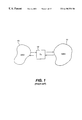
- FIG. 1 illustrates an example of a prior art connection between networks.
- the first network 10 forwards communications within the network 10 according to one communication protocol.
- the second network 11 forwards communication packets around the network 11 using a different communication protocol. Accordingly, if a packet needs to be sent from the first network 10 to the second network 11 , a translation needs to be made.
- a translation unit 12 is included for translating packets from the communication protocol of the first network 10 to the communication protocol of the second network 11 , and vice versa.
- the prior art follows one of two approaches.
- a general purpose computer processor is used to do the translations.
- the processor generally stores the packet in memory, manipulates the packet within that memory to conform to the new protocol and then outputs the translated packet.
- the second approach is to design a custom hardware machine to perform the translation.
- a state machine is hard coded to perform each translation from one format to the other.
- a fast hard coded translator must be designed and implemented for each translation. While common parts of similar translations may be combined to decrease circuitry, this adds significantly to the complexity of hardware verification.
- the hard coded state machine is usually implemented on an application specific integrated circuit (ASIC) or using a programmable logic device (PLD, such as field programmable gate arrays or complex programmable logic devices).
- a translator unit for translating a packet from one communication protocol to a second communication protocol.
- the translator unit comprises an input memory, an information source, an output memory, and a connection circuit that selectively connects the input memory and the information source to the output memory, to selectively write information into the output memory according to the second communication protocol's format.
- the translator unit also includes a microcoded control unit coupled to the connection circuit.
- the microcoded control unit may include a pipeline unit coupled to the connection circuit.
- a pipeline control unit for reading data includes a first memory having a first read latency, a second memory having a second read latency, longer than the first read latency, a pipeline unit having a first stage and a second stage, and a circuit that initiates read cycles from the first memory based on a first instruction in the second stage of the pipeline and which initiates read cycles from the second memory based on a second instruction in the first stage of the pipeline.
- a method of translating a packet is disclosed.
- a first memory is loaded with a set of microcode instructions, each set being designed to perform a different network communication protocol translation.
- the method also includes the steps of receiving an original packet to be translated, selecting one of the sets of the microcode instructions based on the first protocol and the second protocol, and translating the original packet by executing the selected set of microcode instructions.
- a method of translating an original packet into a translated packet is disclosed.
- an instruction memory is loaded with a set of instructions.
- the original packet is placed into an input memory.
- An information source is provided and an output memory to store the translated packets is provided.
- the input memory and the information source are sequentially and selectively connected to the output memory, based on the instructions.
- FIG. 1 illustrates a prior art setting for translation of packets between two communication networks
- FIG. 2 illustrates one embodiment of a translator unit according to the present invention
- FIG. 3 illustrates translation from an original packet to a translated packet according to one embodiment of the present invention
- FIG. 4A illustrates one use of a translation unit according to the present invention
- FIG. 4B illustrates a second embodiment using a translator according to the present invention
- FIG. 4C illustrates a third embodiment using a translator unit according to the present invention to translate packets sent among three networks
- FIG. 5 illustrates the circuit for a multi-protocol translator according to one embodiment of the present invention
- FIG. 6 illustrates one embodiment of a pipeline unit for use in the multi-protocol translator of FIG. 5;
- FIG. 7A illustrates a packet formatted according to the L2 VLAN tagged Ethernet dixie communication protocol
- FIG. 7B illustrates the packet of FIG. 7A, translated to the ATM Forum LANE 2.0 communication protocol
- FIG. 8 illustrates a method of translating a communication packet according to one embodiment of the present invention
- FIG. 9 illustrates another embodiment of a multi-protocol translator according to the present invention, including a double pipeline unit
- FIG. 10 illustrates another embodiment of a multi-protocol translator according to the present invention, including a quad pipeline
- FIG. 11A illustrates one step of translating the packet of FIG. 7A into the packet of FIG. 7B, using the circuit of FIG. 10;
- FIG. 11B illustrates the partial results of the translation, after the step shown in FIG. 11A;
- FIG. 12A illustrates a subsequent step in translating the packet of FIG. 7A into the packet of FIG. 7B, using the circuit of FIG. 10;
- FIG. 12B illustrates the partial results of the translation, after the step illustrated in FIG. 12A is performed
- FIG. 13 illustrates a next step in translating the packet of FIG. 7A into the packet of FIG. 7B, using the circuit of FIG. 10;
- FIG. 14A illustrates a next step in translating the packet of FIG. 7A into the packet of FIG. 7B, using the circuit of FIG. 10;
- FIG. 14B illustrates the partial results after the step illustrated in FIG. 14A
- FIG. 15A illustrates a next step in translating a packet of FIG. 7A into the packet of FIG. 7B, using the circuit of FIG. 10;
- FIG. 15B illustrates the partial results in translating the packet after the step illustrated in FIG. 15 A.
- processors While the use of general purpose processors to perform translations is flexible, the system cannot be optimized for performing packet translation. Accordingly, a processor based system may not be able to meet the performance requirements for fast networks or when there is a lot of traffic through the translator.
- hard coded state machines can be quite expensive. In addition, they are inflexible. If any change is required, a new design must be made. This is a significant problem because communication protocols change frequently and new protocols are promulgated with some frequency. Moreover, the designs typically are difficult to modify to apply in new environments or where additional translations need to be performed by the translator 12 of FIG. 1 .
- One or more embodiments of the present invention achieve a variety of advantages over these prior art systems.
- Certain embodiments of the present invention can achieve one or more of the following goals: the embodiment is fast, being equivalent or close to speed to a custom hardware based translation; real time processor intervention that would slow down translation is unnecessary; the translator can be adapted to perform new translations without extensive new development; the design is flexible and can be configured for multiple protocol translations; the translator is field upgradable (i.e., mistakes or new translations can be addressed with a field upgrade); the implementation is compact; and the translator is scalable—capable of performing trade-offs between speed and complexity.
- FIG. 2 illustrates a simplex translator 28 according to one embodiment of the present invention.
- a simplex translator packets are translated in only one direction.
- a packet would be received from a first network on the network interface 20 a , translated by the translator 28 , and output to a second network by network interface 20 b.
- the network interfaces 20 a , 20 b may be of the same form commonly used in the art to receive and send data packets to/from a network.
- the network interface may be part of known packet switches, routers, bridges or just a physical port with associated hardware.
- the packet typically includes a packet header 22 a .
- the packet header may include a number of fields. One field typically identifies (in some manner) the path over which the packet should traverse. For example, the header could contain a unique path identifier that specifies the entire path through a network.
- the header 22 a may include a destination address, that identifies the intended destination for the packet.
- Many communication protocols include both a destination address and a source address for the packet, as a part of header 22 a .
- the packet may also include a trailer 22 c .
- Both the header and the trailer typically include network, routing, format, error correction and detection, and other types of information, but not the actual data communicated.
- the data to be communicated or “payload” is a continuous block located between the header and trailer (or simply after the header, where there is no trailer), as illustrated at 22 b.
- the input memory 21 a can be any digital memory for storing received packets, including banks of registers, random access memory and other devices.
- the input memory 21 a may be a buffer memory, capable of storing multiple packets which arrive from network interface 20 a but have not yet been translated.
- the controller 24 determines what translation is required. This is done by determining what the current communication protocol format is for the packet and the communication protocol required to forward the packet. Where network interface 20 a is connected to only one type of network and network interface 20 b is connected to only one (different) type of network, this function is simple to implement; the translation is always from one specific protocol to another specific protocol. Where multiple protocols may be placed into input memory 21 a , and multiple protocols may be required for output, the controller may perform a table lookup or other procedure to determine what protocols are required. For example, the destination address and source address for a packet can be used to determine the source and destination protocols for the packet.
- the header 22 a will include information identifying the network protocol, and the destination will determine what the output communication protocol should be. In the event that a table lookup is performed, this may be done using an associated random access memory 25 . Techniques for identifying what particular translation is required are currently known. Where more than one protocol translation is required, the multi-protocol translator (MPT) 26 performs the appropriate translation based on the information provided by the controller 24 . These functions of the controller are described in greater detail below.
- the controller 24 can be implemented in one of many ways. The controller will most likely be implemented using ASICs or programmable logic devices, for speed. A general processor could also be used to perform this function, as the amount of processing required to initiate packets is relatively small and delay incurred from use of a general purpose processor is minimal.
- the translation process is performed by two separate elements—the multi-protocol translator (MPT) 26 and the direct memory access (DMA) controller 27 .
- the MPT 26 translates the header and trailer information from the first protocol (e.g., packet 22 a - 22 c ) into the header and trailer information for the new packet ( 23 a - 23 c ).
- the translated packet is stored in output memory 21 b , and when complete is forwarded to the network interface 20 b for transmission across the second network.
- the MPT 26 could also forward the data portion 22 b of the incoming packet into the output memory 21 b . (This may be particularly useful where a trailer or other field needs to be formulated based on the contents of the entire packet, such as a check-sum field or other error detection or correction fields. By passing the data through the MPT, the applicable field can be accumulated as the output memory is written.) Because no change is required to the payload for most translations, however, in many cases this may be done using only a direct memory access (“DMA”) controller 27 . Thus, the DMA controller 27 can be forwarding data (payload) into the output memory while the MPT 26 is setting up the appropriate header and trailer information for the translated packet.
- DMA direct memory access
- FIG. 3 illustrates the translation process from one packet ( 31 - 33 ) to a packet using a different communication protocol ( 34 - 37 ).
- the first packet includes a header 31 , the remainder of the packet being data 33 .
- the MPT translates the header of the first packet 31 into the new translated header 34 .
- the MPT may also forward some of the payload 32 into the new translated packet, as shown at 35 .
- the DMA controller 27 would then handle the transfer of the remainder of the payload 38 .
- the DMA controller 27 may include also a mechanism to alter byte alignment when multiple bytes are read from an input memory and/or multiple bytes written to an output memory, as explained with reference to the storage alignment units of FIGS. 9 and 10.)
- the MPT might be configured to forward some of the data 32 to the new packet 35 , to accommodate the possibility of variable length headers.
- the length of the header varies.
- One approach to resolving this is to have the system controller look up the header length and have the MPT process only the header, while the DMA transfers only data.
- Another solution, as illustrated in FIG. 3, is to take the maximum header size (here, equivalent to fields 31 and 32 of FIG. 3, which, in this example, includes some data because, in FIG. 3, the actual header is smaller than the assumed maximum header size) and always run that portion of an incoming packet through the MPT. In this case, while some data is unnecessarily transferred through the MPT, there is no need to perform an additional table lookup to determine where the header/data boundary is for the applicable incoming packet.
- FIG. 2 provides for unidirectional translation. That is, packets are only received (and not transmitted) on network interface 20 a , translated by the translator 28 , and transmitted (and no packets received) from network interface 20 b .
- the translator 28 of FIG. 2 to the network of FIG. 1, two translator units 28 would be required. The first translator unit would handle packets traveling from the first network 10 to the second network 11 . The second translator would handle packets traveling in the opposite direction (as in FIG. 4 A).
- the embodiment of FIG. 2 can be modified to handle bidirectional traffic. This can be achieved in at least two different ways. First, additional connections could be provided to permit translation both from memory 21 a to memory 21 b and vice versa. Thus, the DMA controller 27 would be capable of transferring data from the input memory 21 a to the output memory 21 b as before, and would also be able to directly transfer data from the memory 21 b to the memory 21 a when packets are being sent from network interface 20 b to network interface 20 a . Similarly, the MPT 26 would be capable of receiving information for translation from both memories 21 a and 21 b , and writing the translated header (or trailer) information to the other opposite memory.
- input memory 21 a only as an input buffer and output memory 21 b only as an output buffer, but to permit both network interface 20 a and 20 b to provide incoming packets to the input memory 21 a and allow output memory 21 b to provide outgoing packets to both network interface 20 a and 20 b .
- the embodiment of FIG. 2 could remain the same, but adding switches, multiplexers or the equivalent to permit multiple inputs and outputs for the input and output memories 21 a and 21 b.
- FIG. 4A illustrates use of two unidirectional processors for translation between two networks.
- packets sent from a first network 41 to a second network 42 are translated by a translator 44 .
- Packets sent from the second network 42 to the first network 41 are sent through a separate translator 45 . This permits parallel processing, at the expense of added hardware.
- FIG. 4B illustrates use of a single translator unit 46 , as described above, to send packets both from the first network 41 to the second network 42 and vice versa.
- the translator must perform two transactions—NW 1 to NW 2 and NW 2 to NW 1 .
- FIG. 4C illustrates use of a single translator 47 with additional networks.
- the first network 41 , second network 42 and third network 43 each have a different communication protocol.
- the multi-protocol translator 47 can receive packets from all three networks, translate them to the appropriate protocol for the destination network, and forward the packet accordingly.
- similar designs using any number of networks could be implemented.
- the multi-protocol translator 26 should preferably be fast, flexible, programmable to handle multiple (and new) translations and upgradable without having to redesign the entire system.
- FIG. 5 illustrates one embodiment of a multi-protocol translator according to the present invention.
- the multi-protocol translator shown in the embodiment of FIG. 5 works as follows.
- the original frame (or frame to be translated) is held in memory 53 a .
- Substitute information to be inserted into the translated frame is held (or produced) in other mechanisms.
- these information sources are the two FIFO memories 54 and 55 .
- To produce a translated frame data is selectively passed from the input memory 53 a , information sources 54 and 55 , and from instruction operands, into the output memory 58 .
- the outgoing frame is then stored in the output memory 58 .
- the appropriate data is passed through a multiplexer 56 into the output memory.
- a microcoded, pipelined control unit 59 controls the reading of the memories 53 a , 54 and 55 and the passing of data to the output memory 58 through the multiplexer 56 .
- the translator has an input memory 53 a , in which the original frame (the frame to be translated) is stored.
- This input memory 53 a may receive the frame directly from a network interface as described above, or may be an additional buffer internal to the multi-protocol translator.
- an address control unit 53 b controls what memory location is read from the input memory for use in the translation.
- the address control unit 53 b may further control the input memory for writing the original frame into the memory, as could be readily designed by one of skill in the art based on the disclosure provided herein.
- the MPT also includes two first-in-first-out (“FIFO”) memories 54 and 55 . These memories contain new header information that may be required in one of the translations that the MPT can perform. Thus, the two FIFOs 54 , 55 provide alternative information that can be used to replace or supplement the header (or trailer) information in the original frame, during translation. Of course, other mechanisms and other forms of memory could be used in place of FIFOs 54 and 55 . More complicated information sources might include mechanisms to generate new fields based on previous fields, such as a check-sum or other error detection or correction field. The number of information sources may also vary, depending on what translation(s) the MPT can perform.
- a dump memory 57 may be included.
- the dump memory would serve to save information from the original frame (or the entire original frame) for system administration, diagnostic purposes, or for some other form of processing. Addressing of the dump memory 57 may be controlled by an address control unit 57 a.
- a multiplexer 56 selectively provides the appropriate data from the input memory 53 a , FIFO 54 and 55 or from the controller, to the output memory 58 .
- mechanisms other than multiplexers could be used to perform the same function.
- the output memory 58 can be any suitable memory (including registers, random access memory, etc.) to hold the translated frame (or the portion of the frame being translated by the MPT) during processing.
- suitable memory including registers, random access memory, etc.
- multiple input or output buffers may be used, particularly where the buffer may be providing data to more than one network interface.
- the input and output memories may be formed within the same single larger memory unit or made up of multiple smaller memory units.
- the translator control unit is configured to issue read instructions in a pipelined fashion.
- the translator control unit 59 is also microcoded.
- the translator control unit includes an opcode memory 51 a that stores the various instructions required for all of the translations that the MPT is capable of performing. The stepping through of the instructions performed in the opcode memory is controlled by the address control unit 51 b . Instructions are fed from the opcode memory 51 a to a pipeline unit 52 .
- the pipeline is implemented as a three stage, two-register pipeline. One register pipeline of the two-register pipeline is used for opcodes. The other pipeline is used for operands (which are also stored in the opcode memory 51 a ).
- the controller 24 of FIG. 2 selects the appropriate microcoded instructions stored in the opcode memory 51 a for use in the applicable translation (i.e., depending on the original and the new protocol for the translation).
- the controller 24 sets the address control 51 b to the appropriate start place for the translation process.
- the controller 50 takes the opcode information from the pipeline 52 (received from the opcode memory 51 a ) and appropriately sends control signals to the information source components for the translated header, e.g., the input memory 53 a and the FIFOs 54 and 55 .
- the controller controls the multiplexer, which selects the data being fed to the output memory 58 for any given write cycle of the output memory 58 .
- the controller 50 also controls what original frame information is recorded in the dump memory 57 and controls writing output memory 58 by controlling the multiplexer 56 and the output memory 58 (including its associated address control).
- the controller 50 can be implemented using discrete components or as part of an ASIC or using programmable logic arrays.
- the controller 50 may also be implemented using a general purpose central processing unit, although this level of complexity may not be necessary for many implementations.
- the lag time necessary to retrieve information from the various sources that make up the translated header can vary.
- the time required to read from the input memory 53 a may be longer than the time required to read from one of the FIFOs 54 and 55 .
- Information coming directly from the translator control unit 59 could be written immediately.
- the example circuit of FIG. 5 has three different read latencies: input memory (two clocks), FIFO (one clock), and data written from the controller (immediate).
- the pipeline 52 has three stages. For an opcode indicating data is to be transferred from the input memory to the output memory is encountered, the controller issues the appropriate read command to the input memory 53 a when the opcode is in the first register of the pipeline in the pipeline unit 52 . In subsequent stages of the pipeline, that opcode can be ignored, until the last stage, where the controller 50 configures multiplexer 56 to transfer the then-ready data from the input memory 53 a to the output memory 58 .
- the controller 50 causes the multiplexer 56 to transfer the then-ready data from the FIFO to the output memory.
- the applicable opcode is ignored in the first two stages of the pipe, and the applicable write is made in the last stage of the pipe in the pipeline unit 52 .
- FIG. 6 illustrates a simple circuit design for the pipeline unit 52 of FIG. 5 .
- the pipeline is implemented using 8 bit register banks (or latches) 60 .
- the operand is fed through a first set of registers 62 while the opcode is fed through a second set of registers 61 . All of the registers 60 are clocked off of a common system clock CLK.
- Each of the stages of opcodes provides information to the controller 50 .
- the operand from the operand pipe 62 is directed to the output memory 58 , through the multiplexer 56 .
- the opcode memory may also effectively be used as an additional stage of the pipeline. For example, instructions to change the address of the input memory can be taken by the controller 50 and used to immediately begin the address change.
- the operation of the multi-protocol translator illustrated in FIG. 5 can be understood in reference to the following example.
- the example shows conversion from L2 VLAN tagged Ethernet dixie (e.g., FIG. 7A) to ATM Forum LANE 2.0 communication protocol (as shown in FIG. 7 B).
- FIG. 7A illustrates the format of a packet according to the L2 VLAN tagged Ethernet dixie communication protocol.
- a virtual destination address (VDA) and virtual source address (VSA) are the first two fields 71 of the packet 69 .
- a tag type 72 is included.
- a destination address (DA), source address (SA) and ether type fields 73 are included.
- the L2 VLAN tagged Ethernet dixie protocol is known to those of skill in the art.
- a packet of the L2 VLAN tagged Ethernet dixie protocol format illustrated in FIG. 7A is converted to the format of ATM Forum LANE 2.0, as illustrated in FIG. 7 B.
- the first field 75 is a fixed communication protocol identifier and is the same for every packet formatted according to this protocol.
- An ether-type 76 is included (different from the ether type shown in FIG. 7 A).
- An ElanID and LecID fields 77 are included. These fields are determined according to the protocol, and, in this example, loaded into the FIFO for the translation. Destination and source addresses and ether type fields 78 are included, which are identical in content to the corresponding fields 73 of FIG. 7 A.
- a packet according to the ATM Forum LANE 2.0 protocol includes a payload 79 at the end. The payload 79 in the translated packet is identical to the payload 74 of the original packet.
- FIG. 8 illustrates a method of using a multi-protocol translator of FIG. 5 to translate the packet of FIG. 7A (L2 VLAN tagged Ethernet dixie) into the packet of FIG. 7B (ATM Forum LANE 2.0).
- the applicable operation codes in this case, including operands
- the opcode memory 51 A of FIG. 5 This is typically done at initialization, not during translation.
- Block 89 illustrates the normal processing of a packet using one embodiment of a multi-protocol translator according to the present invention.
- the translator waits to receive a packet. Once a packet is received, processing begins at a step 83.
- the packet is loaded into the input memory 53 a of the translator.
- the controller 24 (of FIG. 2) identifies what translation is required. This is done by examining the protocol of the incoming packet and determining (based on the destination of the packet) the protocol to which the packet should be translated.
- FIFO 1 55 of FIG. 5 is also loaded with the ATM Forum LANE 2.0 ether type, ElanID and LecID fields (determined by the controller for the applicable packet using methods known in the art for this communication protocol).
- the payload of the packet ( 74 of FIG. 7A) is directly transferred into the output memory 58 of FIG. 5 (the DMA path is not shown in FIG. 5) step 85.
- the multi-protocol translator unit translates the header information of the original packet into the appropriate header for the translated packet.
- the header translation 88 is performed as illustrated at steps 86 a - 86 d.
- the initial fields of the original packet are dumped (fields 71 , 72 of FIG. 7 A). This may be accomplished either by stepping through these fields of the packet header and writing the information only to the dump memory 57 of FIG. 5 . In the alternative, where the information need not be saved, the controller can simply cause the address control 53 b of the input memory 53 a to jump over these fields.
- the LLC-OUI header is written to the output memory.
- the LLC-OUI field is written directly from the opcode memory. That is, a series of microcode instructions write the operand directly from the pipeline unit 52 to the output memory 58 of FIG. 5 (through multiplexer 56 ).
- the entire field is contained as operands in the opcode memory and transferred by directly writing the operands to the output memory.
- the Ether type, ElanID and LecID fields ( 76 , 77 of FIG. 7B) are written from FIFO 1 55 of FIG. 5 to the output memory 58 .
- the lag time of the FIFO 1 55 read before the output memory can be written is two clock cycles. Accordingly, when an instruction from the opcode memory 51 a is passed to the pipeline 52 , calling for writing data from FIFO 1 55 to the output memory 58 , nothing happens at the first stage. At the second stage, however, the read command is issued to FIFO 1 55 . When the opcode reaches the last stage of the pipeline unit 52 , the data is ready to be read from FIFO 1 to the output memory.
- the instruction when that instruction is in the last stage of the pipeline, the instruction causes the controller 50 to configure the multiplexer 56 to pass data from FIFO 1 55 to the output memory 58 and sets up output memory 58 for the appropriate write.
- a new read is issued from the second stage of the pipeline unit 52 , to setup the next data to be written from FIFO 1 55 to output memory 58 .
- the DA, SA and Ether type fields of the original packet are transferred directly to the output memory 58 (corresponding to field 78 of FIG. 7 B).
- the input memory 53 a is assumed to have a latency period (in clock cycles) longer than the FIFO (two clock cycles rather than one). Accordingly, when the opcode is placed in the pipeline unit 52 , a read command is issued at the first stage of the pipeline 52 .
- the opcode corresponding to transfer of data from input memory 53 a to output memory 58 reaches the last stage of the pipeline 52 , the data is ready to be passed from the input memory 53 a to the output memory 58 (the clock cycles corresponding to the latency of input memory having passed, while the opcode is passing through the pipeline 52 ). Accordingly, when the command reaches the last stage of pipeline 52 , it causes the controller 50 to configure the multiplexer 56 to pass data from the input memory 53 a to the output memory 58 (as well as enabling writing of the output memory 58 ).
- steps 85 and 88 are complete, the complete translated packet is in the output memory 58 of FIG. 5 . Accordingly, at a step 87, the packet can be transferred from the output memory to the network interface for propagation to its applicable destination address. When this is done, processing may continue at step 82.
- the multiplexer 56 of FIG. 5 should be configured so that the data path into the output memory 58 is open before the setup time of the output memory logic, but after the hold time of the multiplexer logic. If the sum of the setup and hold time of the multiplexer plus the hold time of the input path plus the setup of the output logic exceeds one clock cycle, the multiplexer configuration may be performed at an earlier stage (e.g., the second stage) of the pipeline 52 . This would make the multiplexer control logic based on the previous stage rather than decoded from the current last stage.
- a one byte channel is used to move information from the applicable source (pipeline operand, FIFO memory or input memory) to the output memory.
- the throughput of the translator can be increased by providing for a wider data channel.
- FIG. 9 illustrates a multi-protocol translator unit that includes a sixteen bit (two byte) data channel, according to the present invention.
- the incoming, original packets are stored in input memory 90 b , which is controlled by an address control 90 a , as in FIG. 5 .
- the input memory can read two bytes of information from the data packet.
- the translator includes an information memory 91 b , controlled by an address control 91 a .
- Memory 91 b stores information to be written into the translated header, and functions similar to the FIFO memory illustrated in FIG. 5. A difference, however, is that two bytes of information can be read from the information memory 91 b.
- the output memory 97 can receive two bytes of information.
- a and B can be simultaneously written to the output memory.
- a byte of data from the input memory can be provided to the A channel or the B channel of the output memory 97 .
- Multiplexer 92 a selects the applicable byte from the input memory 90 b or the information memory 91 b for provision along the A channel to be written in the output memory 97 .
- multiplexer 92 b selects a byte from the information memory or input memory to be provided to the B channel of the output memory 97 , through multiplexer 95 b .
- Multiplexers 95 a and 95 b select the data lines for connection to the applicable channel of the output memory 97 , permitting data to be written from the translator control unit 98 c , the input memory or information memory data selected by the applicable multiplexer 92 a or 92 b , or the data stored in storage alignment units 93 a and 93 b.
- the storage alignment unit 93 a serves to hold data to be written to the output memory 97 in later clock cycles. Thus, if information needs to be delayed before being written to the output memory, that information can be held for one or more clock cycles in the storage alignment unit 93 a . This permits data to be held and realigned when written to the output memory 97 . For example, if a byte becomes available in the data passed from multiplexer 92 a before the corresponding data to be written in channel B of the output memory 97 is available, the A channel information can be held and delayed in storage alignment unit 93 a . When the corresponding byte for channel B of the output memory 97 is available, the delayed information held in storage alignment unit 93 a can be written to the A channel of the output memory 97 , through multiplexer 95 a.
- the storage alignment unit 93 a includes a multiplexer 96 a and a register 96 b .
- the register is written on every clock cycle. Accordingly, if the data needs to be delayed for more than one clock cycle, the data held in 96 b needs to be refreshed (or maintained) through multiplexer 96 a .
- An example of a translation using the delay units 93 a and 93 b is provided below in connection with an embodiment that has four data channels that may be written to the output memory at one time.
- the control unit 98 c has a similar configuration to the control unit 59 of FIG. 5 .
- An opcode memory 99 b stores the opcodes and operands for controlling the entire translator unit.
- An address control 99 a controls the opcodes being read from the opcode memory 99 b .
- the opcode memory 99 b includes two opcode/operand channels, each sixteen bits wide.
- the first opcode/operand pair is fed to a first pipeline 98 a ′, like the pipeline unit 52 of FIG. 5 .
- the second opcode/operand pair is fed to a second pipeline 98 a ′, also like the pipeline unit 52 of FIG. 5 .
- the two sections 98 a ′, 98 a ′′ of the double pipeline unit 98 a permit separate control for components used in writing the A channel and B channel of output memory 97 .
- the double pipeline unit 98 a includes two three-stage pipelines. In this particular embodiment, three stages were selected to correspond to different latencies from the various components that provide data to the output memory 97 .
- the input memory 90 b might have one read latency, the information memory 91 b a different (e.g., shorter) read latency, and the information being written directly from an operand held in the last stage of either side of the double pipeline unit 98 a having no latency.
- a set of instructions that may be used for the translator unit of FIG. 9 are listed in the following table:
- Each of the opcode/operand pairs listed in Table 2 can be fed to either side of the double pipeline unit 98 a . That is, an entire opcode/operand output from the opcode memory 99 b would include two instructions of the form listed in Table 2—one for each side. In selecting binary opcodes for these instructions, additional bits are dedicated to signal an individual function. One bit signals writing of the output memory 58 . The other bit controlling reads and writes from an alignment storage unit 93 a or 93 b . Thus, each of the above instructions has four forms (encoded with the two extra bits)—any combination of commands for writing the output memory (0 or 1) and writing the applicable storage alignment unit (0 or 1).
- the throughput of the translator unit can be increased.
- the number of channels can of course be increased beyond two.
- FIG. 10 illustrates an embodiment of a translator unit where four channels A, B, C and D can be written simultaneously to an output memory 105 .
- this embodiment has an input memory 100 b for storing the original frame to be translated.
- the input memory 100 b is controlled by an address control unit 100 a .
- information to be inserted into the translated header of the translated packet is stored in an information memory 101 b , which is controlled by an address control unit 101 a .
- four bytes of data can be read from each of the input memory lOOb and information memory 101 b in one clock cycle.
- a set of four multiplexers 102 permit any of the output bytes of the input memory 100 b and information memory 101 b to be fed along a data channel that feeds any of the four input channels A, B, C and D of the output memory 105 .
- a series of four alignment storage units 103 permit a byte being fed along one of the data channels to the output memory to be stored, for alignment with subsequently read data on the other data channels.
- These alignment storage units are of the same configuration as described above with respect to the alignment storage units 93 a and 93 b of FIG. 9 .
- a set of four multiplexers 104 provide the fmal selection as to what data is actually written to the applicable data channel A, B, C, D of the output memory 105 for a particular clock cycle.
- a control unit 109 controls the timing and application of data being written to the output memory 105 .
- this embodiment has an opcode memory 106 b , controlled by an address control unit 106 a. Unlike the earlier embodiments, however, this opcode memory provides a set of four opcodes, each with an applicable operand. Thus, sixty-four bits are provided as an output of the opcode memory 106 b.
- the quad pipe includes four pipelines of the type illustrated and described above with reference to pipeline unit 52 of FIG. 5 .
- Each opcode/operand pair can perform one or more functions with respect to the components in one of the channels providing data to the output memory 105 .
- components in all four of the data channels can be controlled simultaneously and separately.
- this pipeline also has three stages.
- a controller 108 takes the information from each of the stages of the pipeline, and each of the four pipeline units, and uses that information to provide the appropriate control signals for the remainder of the translator unit.
- Table 3 sets forth a set of instructions that may be used to control the translator unit of FIG. 10 .
- each of these opcodes applies to each of the data channels A, B, C, D of the output memory.
- the opcodes of Table 3 apply to just one of the channels, and each read from the opcode memory would produce four of such opcodes.
- two extra bits for each opcode encode whether one or both of the output memory or applicable storage alignment unit is written.
- FIG. 11A illustrates the first write to output memory when using the translator unit of FIG. 10 to translate the packet of FIG. 7A into the packet of FIG. 7 B.
- the pipeline 107 has already received three sets of instructions (over three clock cycles).
- an instruction 112 a - 112 d in each of the four parallel pipelines causes data to be written immediately to the output memory 105 .
- the four operands of the applicable instructions are written to the output memory during the next clock cycle.
- FIGS. 11A-115A the most significant byte is presumed to be at the bottom of the output memory 105 .
- the opcode/operand pairs causes the sequence AA-AA-03-00 (4 bytes of data) to be written simultaneously to the output memory 105 .
- the opcode “write_im” causes the control unit (not shown) to configure the multiplexers 104 to connect the applicable operands to the input of the output memory 105 , as shown.
- FIG. 11B illustrates the state of the output memory after the operation performed in FIG. 11 A. As illustrated, four bytes of the header 118 have been written. The remainder of the translated packet 119 has not yet been written to the output memory.
- FIG. 12A illustrates the next step in translating the packet.
- the last stage 112 of the pipeline unit 107 has two write immediate commands 120 a and 120 b . These two commands write the last two bytes of the fixed header of the translated packet (shown in FIG. 7 B).
- the instructions to read information from the information memory 120 c and 120 d have also reached the last stage of the pipeline. Because the read was initiated during the preceding clock cycle (shown in FIG. 11 A), the information is now ready to be transferred from the information memory 101 b to the output memory 105 . Accordingly, the control unit (not shown) configures the appropriate multiplexers 104 to pass the information directly into the output memory 105 .
- the two bytes of the Ether-type are stored in bytes “0” and “1” of the four byte word stored in the information memory 101 b .
- the illustrated connection transfers the Ether-type bytes to the output memory 105 .
- FIG. 12B illustrates the packet as stored in the output memory 105 after the step illustrated in FIG. 12A takes place. As shown, the leading header and Ether-type have now been written to the output memory 105 , as shown at 125 . The remainder of the translated packet 126 has not yet been written to the output memory 105 .
- FIG. 13A illustrates the next step in the translation.
- the two most significant bytes for the ElanID field are stored in a four byte word in the information memory 101 b , as shown. These two bytes cannot be written directly to the output memory, however, because the output memory requires a four byte word to be written. Accordingly, the two bytes of the ElanID need to be stored in the storage alignment units 103 , for later writing to the output memory 105 . This is done as illustrated in FIG. 13 A. During this clock cycle, no information is written to the output memory. Accordingly, the output memory continues to hold the same partially translated packet of FIG. 12 B.
- the other two pipelines hold two instructions that require reading of information from the input memory 100 b —jump orig B 0 at 131 a (which causes the input memory 100 b to jump to an operand address—to cause the address controller (not shown) of the input memory 100 b to skip over the portions of the original packet header that are not used in the translated packet, i.e., fields 71 , 72 of FIG. 7 A).
- the address controller (not shown) of the input memory 100 b to skip over the portions of the original packet header that are not used in the translated packet, i.e., fields 71 , 72 of FIG. 7 A).
- the read latency of the input memory 110 b is longer than the read latency of the information memory 101 b .
- the control unit causes the input memory's address control unit 100 a to apply the applicable address and initiates a read of the input memory 100 b.
- FIG. 14A illustrate the next clock cycle in this translation.
- the remainder of the ElanID field is present at bytes 0 and 1 of the information memory 101 b . Accordingly, these bytes may be written from the information memory 101 b to the output memory, as is accomplished with instructions 140 c and 140 d .
- These instructions cause the top two multiplexers of the multiplexers 104 to pass the data from bytes 0 and byte 1 of the information memory 101 b to the output memory 105 .
- instructions causing data to be written from the bottom two storage elements of the storage elements 103 to be simultaneously written to the output memory 105 i.e., the instructions 140 a and 140 b ) reach the last stage of the pipeline.
- the last two bytes of the ElanID can be appropriately aligned with the first two bytes for simultaneous writing to the output memory 105 .
- FIG. 14B illustrates the portion of the packets stored in the output memory 105 , after the step illustrated in FIG. 14 A. As is shown, the beginning of the packet through the ElanID field is included 145 . The remainder of the packet 146 remains to be placed into the output memory. (Note, however, that if DMA control is used to transfer the payload to the output memory, a portion of the payload may also be in the output memory at this point and, perhaps, earlier.)
- FIG. 15A illustrates the next clock cycle.
- the first two bytes of the destination address are written to the output memory from the input memory, per the instructions at 150 c and 150 d .
- the read from this memory was initiated back when these instructions appeared in the first stage of the pipeline 110 .
- two instructions 150 a and 150 b cause the two bytes of the LecID to be written to the output memory from the information memory.
- FIG. 15B illustrates the contents of the output memory 105 after the step illustrated in FIG. 15 A. Most of the header has been written 155 , including a portion of the destination address (transferred directly from the equivalent field of the original packet). The remainder of the packet 156 is yet to be written to the output memory.
- the instructions to transfer the remainder of the header of the original packet header to the translated packet in the output memory are shown (the DA, SA and Ether-type fields that remain to be written are all transferred directly from the equivalent fields held in the input memory 100 b ).
- the information is transferred using the storage alignment units, in the manner described above.
- Pipelines with three stages and having a width of 1, 2 and 4 pipelines have been described. Pipelines of varying numbers of stages and varying widths can be constructed. Moreover, the example opcodes are illustrative only. Any number of other byte manipulations could be implemented. Finally, because the translator circuit structure may be built from common components, circuit design lends itself to automated procedures, including automated circuit design and optimization.
Abstract
Description
| TABLE 1 |
| Single Pipe MPT Instructions |
| Name | Operand | Description |
| READ_ORIG | no | Move Byte from input memory to output memory |
| READ_ORIG_DUMP | no | Move Byte from input memory to dump memory |
| READ_FIFO1 | no | Move Byte from FIFO1 to output memory |
| READ_FIFO2 | no | Move Byte from FIFO2 to output memory |
| WRITE_IM | yes | Move operand to output memory |
| JUMP_ORIG_DUMP | yes | Jump to new ORIG address (per operand value) and |
| write to output memory | ||
| JUMP_OPCODE | yes | Go to a “subroutine” address in a opcode memory |
| space | ||
| RETURN_OPCODE | yes | Return to opcode address + 1 which was stored |
| when jump occurred | ||
| RETURN_ORIG | no | Return to input memory address + 1 which was |
| stored when jump occurred | ||
| END | no | Tells controller that translation is finished |
| TABLE 2 | ||
| Name | Operand | Description |
| R_ORIG_U_A | no | read upper Byte lane of input memory and advance |
| address controller | ||
| R_ORIG_L_A | no | read lower Byte lane of input memory and advance |
| address controller | ||
| R_ORIG_U_NA | no | read upper Byte lane of input memory and do not |
| advance address controller | ||
| R_ORIG_U_NA | no | read lower Byte lane of input memory and do not |
| advance address controller | ||
| PRELOAD_ORIG_U | yes | preload input memory address controller with |
| address in operand and read from upper Byte lane | ||
| PRELOAD_ORIG_L | yes | preload input memory address controller with |
| address in operand and read from lower Byte lane | ||
| R_INFO_U_A | no | read upper Byte lane of INFO memory and advance |
| address controller | ||
| R_INFO_L_A | no | read lower Byte lane of INFO memory and advance |
| address controller | ||
| R_INFO_U_NA | no | read upper Byte lane of INFO memory and do not |
| advance address controller | ||
| R_INFO_U_NA | no | read lower Byte lane of INFO memory and do not |
| advance address controller | ||
| PRELOAD_INFO_U | yes | preload INFO memory address controller with |
| address in operand and read from upper Byte lane | ||
| PRELOAD_INFO_L | yes | preload INFO memory address controller with |
| address in operand and read from lower Byte lane | ||
| R_BYTE_STORE | no | read byte stored in Delay Unit |
| WRITE_IM | yes | write operand into output memory |
| JUMP_OPCODE | yes | change the current address of the opcode address |
| controller to the operand. Store off current address | ||
| to opcode jump register | ||
| RETURN_OPCODE | no | change the current address of the opcode to the |
| opcode jump register + 1; | ||
| STALL | no | do not write output memory |
| END | no | end of algorithm |
| TABLE 3 |
| Opcodes |
| Name | Operand | Description |
| R_ORIG_B3_A | no | read Byte lane 3 of input memory and advance |
| address controller | ||
| R_ORIG_B2_A | no | read Byte lane 2 of input memory and advance |
| address controller | ||
| R_ORIG_B1_A | no | read Byte lane 1 of input memory and advance |
| address controller | ||
| R_ORIG_B0_A | no | read Byte lane 0 of input memory and advance |
| address controller | ||
| R_ORIG_B3_NA | no | read Byte lane 3 of input memory and do not |
| advance address controller | ||
| R_ORIG_B2_NA | no | read Byte lane 2 of input memory and do not |
| advance address controller | ||
| R_ORIG_B1_NA | no | read Byte lane 1 of input memory and do not |
| advance address controller | ||
| R_ORIG_B0_NA | no | read Byte lane 0 of input memory and do not |
| advance address controller | ||
| PRELOAD_ORIG_B3 | yes | preload input memory address controller with |
| address in operand and read from Byte lane 3 | ||
| PRELOAD_ORIG_B2 | yes | preload input memory address controller with |
| address in operand and read from Byte lane 2 | ||
| PRELOAD_ORIG_B1 | yes | preload input memory address controller with |
| address in operand and read from Byte lane 1 | ||
| PRELOAD_ORIG_B0 | yes | preload input memory address controller with |
| address in operand and read from Byte lane 0 | ||
| R_INFO_B3_A | no | read Byte lane 3 of info memory and advance |
| address controller | ||
| R_INFO_B2_A | no | read Byte lane 2 of info memory and advance |
| address controller | ||
| R_INFO_B1_A | no | read Byte lane 1 of info memory and advance |
| address controller | ||
| R_INFO_B0_A | no | read Byte lane 0 of info memory and advance |
| address controller | ||
| R_INFO_B3_NA | no | read Byte lane 3 of info memory and do not advance |
| address controller | ||
| R_INFO_B2_NA | no | read Byte lane 2 of info memory and do not advance |
| address controller | ||
| R_INFO_B1_NA | no | read Byte lane 1 of info memory and do not advance |
| address controller | ||
| R_INFO_B0_NA | no | read Byte lane 0 of info memory and do not advance |
| address controller | ||
| PRELOAD_INFO_B3 | yes | preload info memory address controller with address |
| in operand and read from Byte lane 3 | ||
| PRELOAD_INFO_B2 | yes | preload info memory address controller with address |
| in operand and read from Byte lane 2 | ||
| PRELOAD_INFO_B1 | yes | preload info memory address controller with address |
| in operand and read from Byte lane 1 | ||
| PRELOAD_INFO_B0 | yes | preload info memory address controller with address |
| in operand and read from Byte lane 0 | ||
| R_BYTE_STORE | no | read byte stored in Alignment Storage |
| WRITE_IM | yes | write operand into output memory |
| JUMP_OPCODE | yes | change the current address of the opcode address |
| controller to the operand. Store off current address | ||
| to opcode jump register | ||
| RETURN_OPCODE | no | change the current address of the opcode to the |
| opcode jump register + 1; | ||
| STALL | no | do not write output memory |
| END | no | end of algorithm |
Claims (18)
Priority Applications (7)
| Application Number | Priority Date | Filing Date | Title |
|---|---|---|---|
| US08/974,632 US6198751B1 (en) | 1997-11-19 | 1997-11-19 | Multi-protocol packet translator |
| EP98957918A EP1033020B1 (en) | 1997-11-19 | 1998-11-13 | Multi-protocol packet translator |
| AU14060/99A AU729211B2 (en) | 1997-11-19 | 1998-11-13 | Multi-protocol packet translator |
| CA002310741A CA2310741C (en) | 1997-11-19 | 1998-11-13 | Multi-protocol packet translator |
| PCT/US1998/024237 WO1999026376A2 (en) | 1997-11-19 | 1998-11-13 | Multi-protocol packet translator |
| DE69810511T DE69810511T2 (en) | 1997-11-19 | 1998-11-13 | MULTIPLE PROTOCOL PACKAGE TRANSLATOR |
| US09/730,453 US20010033580A1 (en) | 1997-11-19 | 2000-12-05 | Multi-protocol packet translator |
Applications Claiming Priority (1)
| Application Number | Priority Date | Filing Date | Title |
|---|---|---|---|
| US08/974,632 US6198751B1 (en) | 1997-11-19 | 1997-11-19 | Multi-protocol packet translator |
Related Child Applications (1)
| Application Number | Title | Priority Date | Filing Date |
|---|---|---|---|
| US09/730,453 Division US20010033580A1 (en) | 1997-11-19 | 2000-12-05 | Multi-protocol packet translator |
Publications (1)
| Publication Number | Publication Date |
|---|---|
| US6198751B1 true US6198751B1 (en) | 2001-03-06 |
Family
ID=25522278
Family Applications (2)
| Application Number | Title | Priority Date | Filing Date |
|---|---|---|---|
| US08/974,632 Expired - Lifetime US6198751B1 (en) | 1997-11-19 | 1997-11-19 | Multi-protocol packet translator |
| US09/730,453 Abandoned US20010033580A1 (en) | 1997-11-19 | 2000-12-05 | Multi-protocol packet translator |
Family Applications After (1)
| Application Number | Title | Priority Date | Filing Date |
|---|---|---|---|
| US09/730,453 Abandoned US20010033580A1 (en) | 1997-11-19 | 2000-12-05 | Multi-protocol packet translator |
Country Status (6)
| Country | Link |
|---|---|
| US (2) | US6198751B1 (en) |
| EP (1) | EP1033020B1 (en) |
| AU (1) | AU729211B2 (en) |
| CA (1) | CA2310741C (en) |
| DE (1) | DE69810511T2 (en) |
| WO (1) | WO1999026376A2 (en) |
Cited By (50)
| Publication number | Priority date | Publication date | Assignee | Title |
|---|---|---|---|---|
| US20010033580A1 (en) * | 1997-11-19 | 2001-10-25 | Dorsey Paul C. | Multi-protocol packet translator |
| US20020022944A1 (en) * | 2000-08-09 | 2002-02-21 | Birger Gernhardt | Device for analyzing digital data |
| US20020059427A1 (en) * | 2000-07-07 | 2002-05-16 | Hitachi, Ltd. | Apparatus and method for dynamically allocating computer resources based on service contract with user |
| WO2002063831A1 (en) * | 2000-12-30 | 2002-08-15 | Redback Networks Inc. | Method and appatatus for processing of multiple protocols within data transmission signals |
| US6438137B1 (en) * | 1997-12-22 | 2002-08-20 | Nms Communications Corporation | Packet-based trunking |
| WO2002087124A1 (en) * | 2001-04-24 | 2002-10-31 | Crossroads Systems, Inc. | Network analyzer/sniffer with multiple protocol capabilities |
| US20020163916A1 (en) * | 1996-12-16 | 2002-11-07 | Oskouy Rasoul Mirzazadeh | In-line packet processing |
| US20030016699A1 (en) * | 2001-03-31 | 2003-01-23 | Mcclary Michael | Alignment of TDM-based signals for packet transmission using framed and unframed operations |
| US20030023760A1 (en) * | 2001-03-31 | 2003-01-30 | Mcclary Michael | Method and apparatus for sync hunting signals |
| US20030069997A1 (en) * | 2001-08-31 | 2003-04-10 | Philip Bravin | Multi modal communications system |
| US6604136B1 (en) | 1998-06-27 | 2003-08-05 | Intel Corporation | Application programming interfaces and methods enabling a host to interface with a network processor |
| US6603768B1 (en) | 1998-06-27 | 2003-08-05 | Intel Corporation | Multi-protocol conversion assistance method and system for a network accelerator |
| US20030188056A1 (en) * | 2002-03-27 | 2003-10-02 | Suresh Chemudupati | Method and apparatus for packet reformatting |
| US6657959B1 (en) | 1998-06-27 | 2003-12-02 | Intel Corporation | Systems and methods for implementing ABR with guaranteed MCR |
| US6658021B1 (en) * | 1998-06-19 | 2003-12-02 | Juniper Networks, Inc. | Method and system for encapsulating/decapsulating data on a per channel basis in hardware |
| US20040028067A1 (en) * | 1998-06-27 | 2004-02-12 | Softcom Microsystems | Two-dimensional queuing/de-queuing methods and systems for implementing the same |
| US20040073714A1 (en) * | 2001-03-31 | 2004-04-15 | Mcclary Michael | Method and apparatus for deframing signals |
| US20040083309A1 (en) * | 2001-05-15 | 2004-04-29 | Ricoh Company, Ltd. | FIFO device |
| US6735773B1 (en) | 1998-06-27 | 2004-05-11 | Intel Corporation | Method and apparatus for issuing commands to a network processor configured to provide a plurality of APIs |
| US20050005022A1 (en) * | 1999-02-16 | 2005-01-06 | Taylor Rebecca S. | Generic Communications Protocol Translator |
| US20050125562A1 (en) * | 2003-12-04 | 2005-06-09 | Infineon Technologies North America Corp. | Method and apparatus for adapting mac and network processor core to packet format changes and for mapping RPR architecture over spatial reuse architecture |
| US20050147094A1 (en) * | 1999-05-21 | 2005-07-07 | Broadcom Corporation | Address resolution snoop support for CPU |
| US6950446B2 (en) | 2001-03-31 | 2005-09-27 | Redback Networks Inc. | Method and apparatus for simultaneously sync hunting signals |
| US20060004990A1 (en) * | 2004-07-02 | 2006-01-05 | Seagate Technology Llc | Distributed processing in a multiple processing unit environment |
| US20060007946A1 (en) * | 1998-06-19 | 2006-01-12 | Frank Kastenholz | Interconnect network for operation within a communication node |
| US7039800B1 (en) * | 1999-05-24 | 2006-05-02 | Rockwell Collins, Inc. | Translator terminal for two or more wireless networks |
| US7050395B1 (en) | 2001-11-30 | 2006-05-23 | Redback Networks Inc. | Method and apparatus for disabling an interface between network element data processing units |
| US7068675B1 (en) * | 1999-04-09 | 2006-06-27 | Komatsu, Ltd. | Construction machine using the method of controlling communications among electronic devices |
| US7075951B1 (en) | 2001-11-29 | 2006-07-11 | Redback Networks Inc. | Method and apparatus for the operation of a storage unit in a network element |
| US20060176880A1 (en) * | 2005-02-04 | 2006-08-10 | Bare Ballard C | Mesh mirroring with path tags |
| US7113520B1 (en) * | 2001-04-11 | 2006-09-26 | Adl Llc | Local protocol server |
| US7301933B1 (en) * | 2000-12-22 | 2007-11-27 | Cisco Technology, Inc. | Delivery of a service program to a digital signal processor within a multiservice processing system |
| US7308004B1 (en) | 2002-03-06 | 2007-12-11 | Redback Networks, Inc. | Method and apparatus of multiplexing and demultiplexing communication signals |
| US7324539B1 (en) | 2001-11-28 | 2008-01-29 | Redback Networks Inc. | Method and apparatus for processing channelized and unchannelized data within a signal |
| US20080198852A1 (en) * | 1998-09-28 | 2008-08-21 | Juniper Networks, Inc. | Address converter for gateways interconnecting networks of different address formats |
| US20080273518A1 (en) * | 2007-04-13 | 2008-11-06 | Hart Communication Foundation | Suspending Transmissions in a Wireless Network |
| US20080279155A1 (en) * | 2007-04-13 | 2008-11-13 | Hart Communication Foundation | Adaptive Scheduling in a Wireless Network |
| US20090010203A1 (en) * | 2007-04-13 | 2009-01-08 | Hart Communication Foundation | Efficient Addressing in Wireless Hart Protocol |
| US20090046732A1 (en) * | 2007-04-13 | 2009-02-19 | Hart Communication Foundation | Routing Packets on a Network Using Directed Graphs |
| US20090046675A1 (en) * | 2007-04-13 | 2009-02-19 | Hart Communication Foundation | Scheduling Communication Frames in a Wireless Network |
| US20090183362A1 (en) * | 2008-01-18 | 2009-07-23 | Inventec Corporation | Method for manufacturing a transmission line equalizer |
| US20090185275A1 (en) * | 2008-01-18 | 2009-07-23 | Visera Technologies Company Limited | Image sensor device with high photosensitivity |
| WO2009102353A1 (en) * | 2008-02-13 | 2009-08-20 | Hewlett-Packard Development Company, L.P. | Managing electronic devices with different types of device location limited device management clients |
| US20100110916A1 (en) * | 2008-06-23 | 2010-05-06 | Hart Communication Foundation | Wireless Communication Network Analyzer |
| US20100325740A1 (en) * | 2008-02-13 | 2010-12-23 | Osvaldo Diaz | Managing electronic devices using an electronic device as a root of trust |
| US8831021B2 (en) | 2011-09-25 | 2014-09-09 | Qualcomm Incorporated | System and method for dynamically configurable multi-window divergent protocol bridge |
| US20150271140A1 (en) * | 1999-06-15 | 2015-09-24 | Tectia Oyj | Tunnelling of Information |
| US9183560B2 (en) | 2010-05-28 | 2015-11-10 | Daniel H. Abelow | Reality alternate |
| EP3237979A1 (en) * | 2014-12-24 | 2017-11-01 | ABB Schweiz AG | An inter-operable remote terminal unit |
| CN113722013A (en) * | 2021-09-10 | 2021-11-30 | 中国西安卫星测控中心 | Data exchange method suitable for Beidou third-satellite measurement, operation and control system |
Families Citing this family (35)
| Publication number | Priority date | Publication date | Assignee | Title |
|---|---|---|---|---|
| US7487232B1 (en) | 2000-09-13 | 2009-02-03 | Fortinet, Inc. | Switch management system and method |
| US7574495B1 (en) * | 2000-09-13 | 2009-08-11 | Fortinet, Inc. | System and method for managing interworking communications protocols |
| US8250357B2 (en) | 2000-09-13 | 2012-08-21 | Fortinet, Inc. | Tunnel interface for securing traffic over a network |
| US7272643B1 (en) | 2000-09-13 | 2007-09-18 | Fortinet, Inc. | System and method for managing and provisioning virtual routers |
| US7444398B1 (en) * | 2000-09-13 | 2008-10-28 | Fortinet, Inc. | System and method for delivering security services |
| US7389358B1 (en) * | 2000-09-13 | 2008-06-17 | Fortinet, Inc. | Distributed virtual system to support managed, network-based services |
| US7181547B1 (en) * | 2001-06-28 | 2007-02-20 | Fortinet, Inc. | Identifying nodes in a ring network |
| US20030140157A1 (en) * | 2002-01-22 | 2003-07-24 | Beverly Harlan T. | Removing data from contiguous data flows |
| US7151780B1 (en) * | 2002-03-06 | 2006-12-19 | Cisco Technology, Inc. | Arrangement for automated teller machine communications based on bisync to IP conversion |
| US7161904B2 (en) | 2002-06-04 | 2007-01-09 | Fortinet, Inc. | System and method for hierarchical metering in a virtual router based network switch |
| US7376125B1 (en) | 2002-06-04 | 2008-05-20 | Fortinet, Inc. | Service processing switch |
| US7177311B1 (en) * | 2002-06-04 | 2007-02-13 | Fortinet, Inc. | System and method for routing traffic through a virtual router-based network switch |
| US7116665B2 (en) * | 2002-06-04 | 2006-10-03 | Fortinet, Inc. | Methods and systems for a distributed provider edge |
| US7203192B2 (en) * | 2002-06-04 | 2007-04-10 | Fortinet, Inc. | Network packet steering |
| CA2493383C (en) * | 2002-07-16 | 2012-07-10 | Enterasys Networks, Inc. | Apparatus and method for a virtual hierarchial local area network |
| US7096383B2 (en) | 2002-08-29 | 2006-08-22 | Cosine Communications, Inc. | System and method for virtual router failover in a network routing system |
| US7266120B2 (en) * | 2002-11-18 | 2007-09-04 | Fortinet, Inc. | System and method for hardware accelerated packet multicast in a virtual routing system |
| US7720095B2 (en) * | 2003-08-27 | 2010-05-18 | Fortinet, Inc. | Heterogeneous media packet bridging |
| US7873045B2 (en) * | 2003-09-15 | 2011-01-18 | Exar Corporation | Generating an encapsulating header based on encapsulated information provided at protocol-dependent locations |
| US20050078704A1 (en) * | 2003-10-14 | 2005-04-14 | International Business Machines Corporation | Method and apparatus for translating data packets from one network protocol to another |
| US7499419B2 (en) * | 2004-09-24 | 2009-03-03 | Fortinet, Inc. | Scalable IP-services enabled multicast forwarding with efficient resource utilization |
| US7808904B2 (en) * | 2004-11-18 | 2010-10-05 | Fortinet, Inc. | Method and apparatus for managing subscriber profiles |
| US8571061B2 (en) * | 2006-07-07 | 2013-10-29 | Avaya Communications Israel Ltd. | Inter-network translation |
| US8407658B2 (en) * | 2007-02-01 | 2013-03-26 | International Business Machines Corporation | Methods, systems, and computer program products for using direct memory access to initialize a programmable logic device |
| US9276663B2 (en) | 2009-04-17 | 2016-03-01 | Viasat, Inc. | Layer-2 connectivity from switch to access node/gateway |
| US8804730B2 (en) * | 2009-04-17 | 2014-08-12 | Viasat, Inc. | Layer-2 extension services |
| WO2010121214A1 (en) | 2009-04-17 | 2010-10-21 | Viasat, Inc. | Layer-2 connectivity from switch to access node/gateway |
| US8274981B2 (en) * | 2009-04-17 | 2012-09-25 | Viasat, Inc. | Acceleration through a network tunnel |
| WO2010121217A1 (en) | 2009-04-17 | 2010-10-21 | Viasat, Inc. | Mobility across satellite beams using l2 connectivity |
| WO2010121221A1 (en) * | 2009-04-17 | 2010-10-21 | Viasat, Inc. | Multi-satellite architecture |
| US8345650B2 (en) * | 2009-04-17 | 2013-01-01 | Viasat, Inc. | Access node/gateway to access node/gateway layer-2 connectivity (end-to-end) |
| WO2010121219A2 (en) * | 2009-04-17 | 2010-10-21 | Viasat, Inc. | Core-based satellite network architecture |
| US8526363B2 (en) * | 2010-01-13 | 2013-09-03 | Sony Corporation | Method and system for transferring data between wireless devices |
| US9503552B2 (en) * | 2014-05-09 | 2016-11-22 | Google Inc. | System and method for adapting to network protocol updates |
| US11711299B2 (en) * | 2020-01-10 | 2023-07-25 | Cisco Technology, Inc. | Traffic mirroring in hybrid network environments |
Citations (8)
| Publication number | Priority date | Publication date | Assignee | Title |
|---|---|---|---|---|
| EP0289248A2 (en) | 1987-05-01 | 1988-11-02 | AT&T Corp. | Programmable protocol engine |
| US5117429A (en) * | 1988-08-05 | 1992-05-26 | Lmt Radio Professinnelle | Packet switch for a transfer of data in asynchronous mode in a digital transmission network |
| US5651002A (en) * | 1995-07-12 | 1997-07-22 | 3Com Corporation | Internetworking device with enhanced packet header translation and memory |
| US5655140A (en) | 1994-07-22 | 1997-08-05 | Network Peripherals | Apparatus for translating frames of data transferred between heterogeneous local area networks |
| US5717910A (en) * | 1996-03-29 | 1998-02-10 | Integrated Device Technology, Inc. | Operand compare/release apparatus and method for microinstrution sequences in a pipeline processor |
| US5787255A (en) * | 1996-04-12 | 1998-07-28 | Cisco Systems, Inc. | Internetworking device with enhanced protocol translation circuit |
| US5812792A (en) * | 1994-07-22 | 1998-09-22 | Network Peripherals, Inc. | Use of video DRAM for memory storage in a local area network port of a switching hub |
| US5832236A (en) * | 1996-05-20 | 1998-11-03 | Compaq Computer Corporation | High speed frame translation for computer networks |
Family Cites Families (5)
| Publication number | Priority date | Publication date | Assignee | Title |
|---|---|---|---|---|
| US4025771A (en) * | 1974-03-25 | 1977-05-24 | Hughes Aircraft Company | Pipe line high speed signal processor |
| US5253360A (en) * | 1988-12-16 | 1993-10-12 | Kabushiki Kaisha Toshiba | Facsimile device having continuous operating capabilities immediately after recovery from trouble and related method |
| US5809552A (en) * | 1992-01-29 | 1998-09-15 | Fujitsu Limited | Data processing system, memory access device and method including selecting the number of pipeline stages based on pipeline conditions |
| US6172990B1 (en) * | 1997-06-19 | 2001-01-09 | Xaqti Corporation | Media access control micro-RISC stream processor and method for implementing the same |
| US6198751B1 (en) * | 1997-11-19 | 2001-03-06 | Cabletron Systems, Inc. | Multi-protocol packet translator |
-
1997
- 1997-11-19 US US08/974,632 patent/US6198751B1/en not_active Expired - Lifetime
-
1998
- 1998-11-13 AU AU14060/99A patent/AU729211B2/en not_active Ceased
- 1998-11-13 EP EP98957918A patent/EP1033020B1/en not_active Expired - Lifetime
- 1998-11-13 DE DE69810511T patent/DE69810511T2/en not_active Expired - Lifetime
- 1998-11-13 CA CA002310741A patent/CA2310741C/en not_active Expired - Fee Related
- 1998-11-13 WO PCT/US1998/024237 patent/WO1999026376A2/en active IP Right Grant
-
2000
- 2000-12-05 US US09/730,453 patent/US20010033580A1/en not_active Abandoned
Patent Citations (8)
| Publication number | Priority date | Publication date | Assignee | Title |
|---|---|---|---|---|
| EP0289248A2 (en) | 1987-05-01 | 1988-11-02 | AT&T Corp. | Programmable protocol engine |
| US5117429A (en) * | 1988-08-05 | 1992-05-26 | Lmt Radio Professinnelle | Packet switch for a transfer of data in asynchronous mode in a digital transmission network |
| US5655140A (en) | 1994-07-22 | 1997-08-05 | Network Peripherals | Apparatus for translating frames of data transferred between heterogeneous local area networks |
| US5812792A (en) * | 1994-07-22 | 1998-09-22 | Network Peripherals, Inc. | Use of video DRAM for memory storage in a local area network port of a switching hub |
| US5651002A (en) * | 1995-07-12 | 1997-07-22 | 3Com Corporation | Internetworking device with enhanced packet header translation and memory |
| US5717910A (en) * | 1996-03-29 | 1998-02-10 | Integrated Device Technology, Inc. | Operand compare/release apparatus and method for microinstrution sequences in a pipeline processor |
| US5787255A (en) * | 1996-04-12 | 1998-07-28 | Cisco Systems, Inc. | Internetworking device with enhanced protocol translation circuit |
| US5832236A (en) * | 1996-05-20 | 1998-11-03 | Compaq Computer Corporation | High speed frame translation for computer networks |
Non-Patent Citations (4)
| Title |
|---|
| A.S. Krishnakumar, et al., The Programmable Protocol VLSI Engine (Prove), Jun. 14, 1992, Supercomm, ICC '92. |
| A.S. Krishnakumar, et al., VLSI Implementations of Communication Protocols-A Survey, Sep. 1989, IEEE Journal on Selected Areas in Communications. |
| Matthias Kaiserswerth, The Parallel Protocol Engine, Dec. 1993, IEEE/ACM Transactions on Networking. |
| Patent Specification, P.2, L. 14-25. |
Cited By (115)
| Publication number | Priority date | Publication date | Assignee | Title |
|---|---|---|---|---|
| US20020163916A1 (en) * | 1996-12-16 | 2002-11-07 | Oskouy Rasoul Mirzazadeh | In-line packet processing |
| US7209448B2 (en) * | 1996-12-16 | 2007-04-24 | Juniper Networks, Inc. | In-line packet processing |
| US20010033580A1 (en) * | 1997-11-19 | 2001-10-25 | Dorsey Paul C. | Multi-protocol packet translator |
| US6438137B1 (en) * | 1997-12-22 | 2002-08-20 | Nms Communications Corporation | Packet-based trunking |
| US8432921B2 (en) | 1998-06-19 | 2013-04-30 | Juniper Networks, Inc. | Bundling data in a single optical channel |
| US7809015B1 (en) | 1998-06-19 | 2010-10-05 | Juniper Networks, Inc. | Bundling ATM and POS data in a single optical channel |
| US9077777B2 (en) | 1998-06-19 | 2015-07-07 | Juniper Networks, Inc. | Encapsulating/decapsulating data in hardware |
| US20060007946A1 (en) * | 1998-06-19 | 2006-01-12 | Frank Kastenholz | Interconnect network for operation within a communication node |
| US8306028B2 (en) | 1998-06-19 | 2012-11-06 | Juniper Networks, Inc. | Interconnect network for operation within a communication node |
| US20100067523A1 (en) * | 1998-06-19 | 2010-03-18 | Juniper Networks, Inc. | Interconnect network for operation within a communication node |
| US7613173B2 (en) | 1998-06-19 | 2009-11-03 | Juniper Networks, Inc. | Interconnect network for operation within a communication node |
| US6658021B1 (en) * | 1998-06-19 | 2003-12-02 | Juniper Networks, Inc. | Method and system for encapsulating/decapsulating data on a per channel basis in hardware |
| US20040028067A1 (en) * | 1998-06-27 | 2004-02-12 | Softcom Microsystems | Two-dimensional queuing/de-queuing methods and systems for implementing the same |
| US6735773B1 (en) | 1998-06-27 | 2004-05-11 | Intel Corporation | Method and apparatus for issuing commands to a network processor configured to provide a plurality of APIs |
| US6604136B1 (en) | 1998-06-27 | 2003-08-05 | Intel Corporation | Application programming interfaces and methods enabling a host to interface with a network processor |
| US6657959B1 (en) | 1998-06-27 | 2003-12-02 | Intel Corporation | Systems and methods for implementing ABR with guaranteed MCR |
| US6603768B1 (en) | 1998-06-27 | 2003-08-05 | Intel Corporation | Multi-protocol conversion assistance method and system for a network accelerator |
| US7411968B2 (en) | 1998-06-27 | 2008-08-12 | Intel Corporation | Two-dimensional queuing/de-queuing methods and systems for implementing the same |
| US6724767B1 (en) | 1998-06-27 | 2004-04-20 | Intel Corporation | Two-dimensional queuing/de-queuing methods and systems for implementing the same |
| US6708210B2 (en) | 1998-06-27 | 2004-03-16 | Intel Corporation | Application programming interfaces and methods enabling a host to interface with a network processor |
| US8077724B2 (en) | 1998-08-04 | 2011-12-13 | Juniper Networks, Inc. | In-line packet processing |
| US9912590B2 (en) | 1998-08-04 | 2018-03-06 | Juniper Networks, Inc. | In-line packet processing |
| US20070147257A1 (en) * | 1998-08-04 | 2007-06-28 | Juniper Networks, Inc. | In-line packet processing |
| US20100309916A1 (en) * | 1998-08-04 | 2010-12-09 | Juniper Networks, Inc. | In-line packet processing |
| US7804833B2 (en) | 1998-08-04 | 2010-09-28 | Juniper Networks, Inc. | In-line packet processing |
| US8867543B2 (en) | 1998-08-04 | 2014-10-21 | Juniper Networks, Inc. | In-line packet processing |
| US20080031252A1 (en) * | 1998-08-04 | 2008-02-07 | Oskouy Rasoul M | In-line packet processing |
| US9479436B2 (en) | 1998-08-04 | 2016-10-25 | Juniper Networks Inc. | In-line packet processing |
| US7801140B2 (en) | 1998-08-04 | 2010-09-21 | Juniper Networks, Inc. | In-line packet processing |
| US20080198852A1 (en) * | 1998-09-28 | 2008-08-21 | Juniper Networks, Inc. | Address converter for gateways interconnecting networks of different address formats |
| US8077711B2 (en) * | 1998-09-28 | 2011-12-13 | Juniper Networks, Inc. | Address converter for gateways interconnecting networks of different address formats |
| US7792981B2 (en) * | 1999-02-16 | 2010-09-07 | Taylor Rebecca S | Generic communications protocol translator |
| US8341281B2 (en) | 1999-02-16 | 2012-12-25 | Lubec Campobello Llc | Generic communications protocol translator |
| US20110004694A1 (en) * | 1999-02-16 | 2011-01-06 | Taylor Rebecca S | Generic communications protocol translator |
| US20050005022A1 (en) * | 1999-02-16 | 2005-01-06 | Taylor Rebecca S. | Generic Communications Protocol Translator |
| US7068675B1 (en) * | 1999-04-09 | 2006-06-27 | Komatsu, Ltd. | Construction machine using the method of controlling communications among electronic devices |
| US7764674B2 (en) * | 1999-05-21 | 2010-07-27 | Broadcom Corporation | Address resolution snoop support for CPU |
| US20050147094A1 (en) * | 1999-05-21 | 2005-07-07 | Broadcom Corporation | Address resolution snoop support for CPU |
| US7039800B1 (en) * | 1999-05-24 | 2006-05-02 | Rockwell Collins, Inc. | Translator terminal for two or more wireless networks |
| US20150271140A1 (en) * | 1999-06-15 | 2015-09-24 | Tectia Oyj | Tunnelling of Information |
| US20020059427A1 (en) * | 2000-07-07 | 2002-05-16 | Hitachi, Ltd. | Apparatus and method for dynamically allocating computer resources based on service contract with user |
| US6928587B2 (en) * | 2000-08-09 | 2005-08-09 | Tektronix International Sales Gmbh | Device for analyzing digital data |
| US20020022944A1 (en) * | 2000-08-09 | 2002-02-21 | Birger Gernhardt | Device for analyzing digital data |
| US7301933B1 (en) * | 2000-12-22 | 2007-11-27 | Cisco Technology, Inc. | Delivery of a service program to a digital signal processor within a multiservice processing system |
| WO2002063831A1 (en) * | 2000-12-30 | 2002-08-15 | Redback Networks Inc. | Method and appatatus for processing of multiple protocols within data transmission signals |
| US6765916B1 (en) | 2000-12-30 | 2004-07-20 | Redback Networks Inc. | Method and apparatus for processing of multiple protocols within data transmission signals |
| US20040073714A1 (en) * | 2001-03-31 | 2004-04-15 | Mcclary Michael | Method and apparatus for deframing signals |
| US6959008B2 (en) | 2001-03-31 | 2005-10-25 | Redback Networks Inc. | Alignment of TDM-based signals for packet transmission using framed and unframed operations |
| US20030016699A1 (en) * | 2001-03-31 | 2003-01-23 | Mcclary Michael | Alignment of TDM-based signals for packet transmission using framed and unframed operations |
| US20030023760A1 (en) * | 2001-03-31 | 2003-01-30 | Mcclary Michael | Method and apparatus for sync hunting signals |
| US7593432B2 (en) | 2001-03-31 | 2009-09-22 | Redback Networks Inc. | Method and apparatus for deframing signals |
| US6941381B2 (en) | 2001-03-31 | 2005-09-06 | Redback Networks Inc. | Method and apparatus for sync hunting signals |
| US6950446B2 (en) | 2001-03-31 | 2005-09-27 | Redback Networks Inc. | Method and apparatus for simultaneously sync hunting signals |
| US20070008976A1 (en) * | 2001-04-11 | 2007-01-11 | Aol Llc | Local Protocol Server |
| US7769042B2 (en) | 2001-04-11 | 2010-08-03 | Aol Inc. | Local protocol server |
| US7113520B1 (en) * | 2001-04-11 | 2006-09-26 | Adl Llc | Local protocol server |
| WO2002087124A1 (en) * | 2001-04-24 | 2002-10-31 | Crossroads Systems, Inc. | Network analyzer/sniffer with multiple protocol capabilities |
| US6894979B1 (en) * | 2001-04-24 | 2005-05-17 | Crossroads Systems, Inc. | Network analyzer/sniffer with multiple protocol capabilities |
| US20040083309A1 (en) * | 2001-05-15 | 2004-04-29 | Ricoh Company, Ltd. | FIFO device |
| US7606941B2 (en) * | 2001-05-15 | 2009-10-20 | Ricoh Company, Ltd. | FIFO device |
| US7333507B2 (en) * | 2001-08-31 | 2008-02-19 | Philip Bravin | Multi modal communications system |
| US20030069997A1 (en) * | 2001-08-31 | 2003-04-10 | Philip Bravin | Multi modal communications system |
| US7324539B1 (en) | 2001-11-28 | 2008-01-29 | Redback Networks Inc. | Method and apparatus for processing channelized and unchannelized data within a signal |
| US7075951B1 (en) | 2001-11-29 | 2006-07-11 | Redback Networks Inc. | Method and apparatus for the operation of a storage unit in a network element |
| US7050395B1 (en) | 2001-11-30 | 2006-05-23 | Redback Networks Inc. | Method and apparatus for disabling an interface between network element data processing units |
| US7308004B1 (en) | 2002-03-06 | 2007-12-11 | Redback Networks, Inc. | Method and apparatus of multiplexing and demultiplexing communication signals |
| US20030188056A1 (en) * | 2002-03-27 | 2003-10-02 | Suresh Chemudupati | Method and apparatus for packet reformatting |
| US20050125562A1 (en) * | 2003-12-04 | 2005-06-09 | Infineon Technologies North America Corp. | Method and apparatus for adapting mac and network processor core to packet format changes and for mapping RPR architecture over spatial reuse architecture |
| US7441039B2 (en) * | 2003-12-04 | 2008-10-21 | Exar Corporation | Method and apparatus for adapting mac and network processor core to packet format changes and for mapping RPR architecture over spatial reuse architecture |
| US20060004990A1 (en) * | 2004-07-02 | 2006-01-05 | Seagate Technology Llc | Distributed processing in a multiple processing unit environment |
| US7441106B2 (en) | 2004-07-02 | 2008-10-21 | Seagate Technology Llc | Distributed processing in a multiple processing unit environment |
| US9544216B2 (en) * | 2005-02-04 | 2017-01-10 | Hewlett Packard Enterprise Development Lp | Mesh mirroring with path tags |
| US20060176880A1 (en) * | 2005-02-04 | 2006-08-10 | Bare Ballard C | Mesh mirroring with path tags |
| US20090010203A1 (en) * | 2007-04-13 | 2009-01-08 | Hart Communication Foundation | Efficient Addressing in Wireless Hart Protocol |
| US8942219B2 (en) | 2007-04-13 | 2015-01-27 | Hart Communication Foundation | Support for network management and device communications in a wireless network |
| WO2009008935A3 (en) * | 2007-04-13 | 2010-03-11 | Hart Communication Foundation | Support for network management and device communications in a wireless network |
| US20080273518A1 (en) * | 2007-04-13 | 2008-11-06 | Hart Communication Foundation | Suspending Transmissions in a Wireless Network |
| US20080279155A1 (en) * | 2007-04-13 | 2008-11-13 | Hart Communication Foundation | Adaptive Scheduling in a Wireless Network |
| US20080279204A1 (en) * | 2007-04-13 | 2008-11-13 | Hart Communication Foundation | Increasing Reliability and Reducing Latency in a Wireless Network |
| US20090010233A1 (en) * | 2007-04-13 | 2009-01-08 | Hart Communication Foundation | Wireless Gateway in a Process Control Environment Supporting a Wireless Communication Protocol |
| US20090010205A1 (en) * | 2007-04-13 | 2009-01-08 | Hart Communication Foundation | Priority-Based Scheduling and Routing in a Wireless Network |
| US20110216656A1 (en) * | 2007-04-13 | 2011-09-08 | Hart Communication Foundation | Routing Packets on a Network Using Directed Graphs |
| US8892769B2 (en) | 2007-04-13 | 2014-11-18 | Hart Communication Foundation | Routing packets on a network using directed graphs |
| US20090052429A1 (en) * | 2007-04-13 | 2009-02-26 | Hart Communication Foundation | Synchronizing Timeslots in a Wireless Communication Protocol |
| US8169974B2 (en) | 2007-04-13 | 2012-05-01 | Hart Communication Foundation | Suspending transmissions in a wireless network |
| US8230108B2 (en) | 2007-04-13 | 2012-07-24 | Hart Communication Foundation | Routing packets on a network using directed graphs |
| US20090054033A1 (en) * | 2007-04-13 | 2009-02-26 | Hart Communication Foundation | Enhancing Security in a Wireless Network |
| US8325627B2 (en) | 2007-04-13 | 2012-12-04 | Hart Communication Foundation | Adaptive scheduling in a wireless network |
| US20090046675A1 (en) * | 2007-04-13 | 2009-02-19 | Hart Communication Foundation | Scheduling Communication Frames in a Wireless Network |
| US8356431B2 (en) | 2007-04-13 | 2013-01-22 | Hart Communication Foundation | Scheduling communication frames in a wireless network |
| US8406248B2 (en) | 2007-04-13 | 2013-03-26 | Hart Communication Foundation | Priority-based scheduling and routing in a wireless network |
| US20090046732A1 (en) * | 2007-04-13 | 2009-02-19 | Hart Communication Foundation | Routing Packets on a Network Using Directed Graphs |
| US20090010204A1 (en) * | 2007-04-13 | 2009-01-08 | Hart Communication Foundation | Support for Network Management and Device Communications in a Wireless Network |
| US8451809B2 (en) | 2007-04-13 | 2013-05-28 | Hart Communication Foundation | Wireless gateway in a process control environment supporting a wireless communication protocol |
| US8798084B2 (en) | 2007-04-13 | 2014-08-05 | Hart Communication Foundation | Increasing reliability and reducing latency in a wireless network |
| US8570922B2 (en) | 2007-04-13 | 2013-10-29 | Hart Communication Foundation | Efficient addressing in wireless hart protocol |
| US8660108B2 (en) | 2007-04-13 | 2014-02-25 | Hart Communication Foundation | Synchronizing timeslots in a wireless communication protocol |
| US8670749B2 (en) | 2007-04-13 | 2014-03-11 | Hart Communication Foundation | Enhancing security in a wireless network |
| US8670746B2 (en) | 2007-04-13 | 2014-03-11 | Hart Communication Foundation | Enhancing security in a wireless network |
| US8676219B2 (en) | 2007-04-13 | 2014-03-18 | Hart Communication Foundation | Combined wired and wireless communications with field devices in a process control environment |
| US20090183362A1 (en) * | 2008-01-18 | 2009-07-23 | Inventec Corporation | Method for manufacturing a transmission line equalizer |
| US20090185275A1 (en) * | 2008-01-18 | 2009-07-23 | Visera Technologies Company Limited | Image sensor device with high photosensitivity |
| US20100332639A1 (en) * | 2008-02-13 | 2010-12-30 | Osvaldo Diaz | Providing Manageability To An Electronic Device That Supports Location Limited Manageability Functionality |
| US8479262B2 (en) | 2008-02-13 | 2013-07-02 | Hewlett-Packard Development Company, L.P. | Managing electronic devices using an electronic device as a root of trust |
| US20100325625A1 (en) * | 2008-02-13 | 2010-12-23 | Osvaldo Diaz | Managing electronic devices with different types of device location limited device management clients |
| US20100325740A1 (en) * | 2008-02-13 | 2010-12-23 | Osvaldo Diaz | Managing electronic devices using an electronic device as a root of trust |
| WO2009102353A1 (en) * | 2008-02-13 | 2009-08-20 | Hewlett-Packard Development Company, L.P. | Managing electronic devices with different types of device location limited device management clients |
| US8441947B2 (en) | 2008-06-23 | 2013-05-14 | Hart Communication Foundation | Simultaneous data packet processing |
| US20100110916A1 (en) * | 2008-06-23 | 2010-05-06 | Hart Communication Foundation | Wireless Communication Network Analyzer |
| US9183560B2 (en) | 2010-05-28 | 2015-11-10 | Daniel H. Abelow | Reality alternate |
| US11222298B2 (en) | 2010-05-28 | 2022-01-11 | Daniel H. Abelow | User-controlled digital environment across devices, places, and times with continuous, variable digital boundaries |
| US8831021B2 (en) | 2011-09-25 | 2014-09-09 | Qualcomm Incorporated | System and method for dynamically configurable multi-window divergent protocol bridge |
| EP3237979A1 (en) * | 2014-12-24 | 2017-11-01 | ABB Schweiz AG | An inter-operable remote terminal unit |
| CN113722013A (en) * | 2021-09-10 | 2021-11-30 | 中国西安卫星测控中心 | Data exchange method suitable for Beidou third-satellite measurement, operation and control system |
| CN113722013B (en) * | 2021-09-10 | 2023-07-28 | 中国西安卫星测控中心 | Data exchange method suitable for Beidou No. three satellite measurement, operation and control system |
Also Published As
| Publication number | Publication date |
|---|---|
| EP1033020B1 (en) | 2003-01-02 |
| EP1033020A2 (en) | 2000-09-06 |
| CA2310741A1 (en) | 1999-05-29 |
| WO1999026376A3 (en) | 1999-11-25 |
| AU729211B2 (en) | 2001-01-25 |
| AU1406099A (en) | 1999-06-07 |
| US20010033580A1 (en) | 2001-10-25 |
| CA2310741C (en) | 2004-04-13 |
| WO1999026376A2 (en) | 1999-05-27 |
| DE69810511D1 (en) | 2003-02-06 |
| DE69810511T2 (en) | 2003-10-02 |
Similar Documents
| Publication | Publication Date | Title |
|---|---|---|
| US6198751B1 (en) | Multi-protocol packet translator | |
| US8346998B2 (en) | System and method for transmitting data packets in a computer system having a memory hub architecture | |
| US6731631B1 (en) | System, method and article of manufacture for updating a switching table in a switch fabric chipset system | |
| US6804731B1 (en) | System, method and article of manufacture for storing an incoming datagram in switch matrix in a switch fabric chipset system | |
| EP0606368B1 (en) | Packet processing method and apparatus | |
| US7616562B1 (en) | Systems and methods for handling packet fragmentation | |
| US7773599B1 (en) | Packet fragment handling | |
| US7382788B2 (en) | Method and apparatus for implementing a data frame processing model | |
| US20070180310A1 (en) | Multi-core architecture with hardware messaging | |
| US7936758B2 (en) | Logical separation and accessing of descriptor memories | |
| US6052383A (en) | LAN to ATM backbone switch module | |
| US8085780B1 (en) | Optimized buffer loading for packet header processing | |
| US5125096A (en) | System for implementing to a packet switch protocol for a multinode data communications network utilizing separate data and control paths | |
| US6724759B1 (en) | System, method and article of manufacture for transferring a packet from a port controller to a switch fabric in a switch fabric chipset system | |
| US5592488A (en) | Method and apparatus for pipelined multiplexing employing analog delays for a multiport interface | |
| US7239630B1 (en) | Dedicated processing resources for packet header generation | |
| KR100264875B1 (en) | High speed cyclical redundancy check system using a programmable architecture | |
| US6208645B1 (en) | Time multiplexing of cyclic redundancy functions in point-to-point ringlet-based computer systems | |
| JP2003521156A (en) | Apparatus and method for sharing memory using a single ring data bus connection configuration | |
| US7158520B1 (en) | Mailbox registers for synchronizing header processing execution | |
| US20040078459A1 (en) | Switch operation scheduling mechanism with concurrent connection and queue scheduling | |
| US20030046458A1 (en) | Data transfer equipment and aligner included in data transfer equipment | |
| US7272151B2 (en) | Centralized switching fabric scheduler supporting simultaneous updates | |
| JP4588560B2 (en) | Table device and address search device using the same | |
| JP3638625B2 (en) | Multiple processing equipment |
Legal Events
| Date | Code | Title | Description |
|---|---|---|---|
| AS | Assignment |
Owner name: CABLETRON SYSTEMS, INC., NEW HAMPSHIRE Free format text: ASSIGNMENT OF ASSIGNORS INTEREST;ASSIGNORS:DORSEY, PAUL C.;FRAZIER, KEVIN M.;DECAROLIS, PETER;REEL/FRAME:008878/0694;SIGNING DATES FROM 19971117 TO 19971118 |
|
| AS | Assignment |
Owner name: ENTERASYS NETWORKS, INC., NEW HAMPSHIRE Free format text: ASSIGNMENT OF ASSIGNORS INTEREST;ASSIGNOR:CABLETRON SYSTEMS, INC.;REEL/FRAME:011219/0376 Effective date: 20000929 |
|
| STCF | Information on status: patent grant |
Free format text: PATENTED CASE |
|
| FEPP | Fee payment procedure |
Free format text: PAYOR NUMBER ASSIGNED (ORIGINAL EVENT CODE: ASPN); ENTITY STATUS OF PATENT OWNER: LARGE ENTITY |
|
| FPAY | Fee payment |
Year of fee payment: 4 |
|
| AS | Assignment |
Owner name: OBSIDIAN, LLC, CALIFORNIA Free format text: SECURITY AGREEMENT;ASSIGNOR:ENTERASYS NETWORKS, INC.;REEL/FRAME:017656/0552 Effective date: 20060516 Owner name: WELLS FARGO FOOTHILL, INC., CALIFORNIA Free format text: SECURITY AGREEMENT;ASSIGNOR:ENTERASYS NETWORKS, INC.;REEL/FRAME:017656/0552 Effective date: 20060516 |
|
| FPAY | Fee payment |
Year of fee payment: 8 |
|
| REMI | Maintenance fee reminder mailed | ||
| AS | Assignment |
Owner name: WELLS FARGO TRUST CORPORATION LIMITED, AS SECURITY Free format text: GRANT OF SECURITY INTEREST IN U.S. PATENTS;ASSIGNOR:ENTERASYS NETWORKS INC.;REEL/FRAME:025339/0875 Effective date: 20101109 |
|
| AS | Assignment |
Owner name: ENTERASYS NETWORKS, INC., MASSACHUSETTS Free format text: RELEASE AND REASSIGNMENT OF PATENTS AND PATENT APPLICATIONS AT REEL/FRAME NO. 17656/0552;ASSIGNORS:WELLS FARGO CAPITAL FINANCE, INC. (FORMERLY KNOWN AS WELLS FARGO FOOTHILL, INC.);ENTERPRISE COMMUNICATIONS FUNDING GMBH, AS SUCCESSOR IN INTEREST TO OBSIDIAN, LLC;REEL/FRAME:025406/0769 Effective date: 20101110 |
|
| FPAY | Fee payment |
Year of fee payment: 12 |
|
| AS | Assignment |
Owner name: ENTERASYS NETWORKS INC., MASSACHUSETTS Free format text: TERMINATION AND RELEASE OF SECURITY INTEREST IN PATENTS AT REEL/FRAME NO. 25339/0875;ASSIGNOR:WELLS FARGO TRUST CORPORATION LIMITED;REEL/FRAME:031558/0677 Effective date: 20131031 |
|
| AS | Assignment |
Owner name: SILICON VALLEY BANK, CALIFORNIA Free format text: SECURITY AGREEMENT;ASSIGNOR:ENTERASYS NETWORKS, INC.;REEL/FRAME:036189/0509 Effective date: 20150724 |
|
| AS | Assignment |
Owner name: EXTREME NETWORKS, INC., NEW HAMPSHIRE Free format text: ASSIGNMENT OF ASSIGNORS INTEREST;ASSIGNOR:ENTERASYS NETWORKS, INC.;REEL/FRAME:036467/0566 Effective date: 20150820 |
|
| AS | Assignment |
Owner name: EXTREME NETWORKS, INC., CALIFORNIA Free format text: ASSIGNMENT OF ASSIGNORS INTEREST;ASSIGNOR:ENTERASYS NETWORKS, INC.;REEL/FRAME:036538/0011 Effective date: 20150820 |
|
| AS | Assignment |
Owner name: SILICON VALLEY BANK, CALIFORNIA Free format text: AMENDED AND RESTATED PATENT AND TRADEMARK SECURITY AGREEMENT;ASSIGNOR:EXTREME NETWORKS, INC.;REEL/FRAME:040521/0762 Effective date: 20161028 |
|
| AS | Assignment |
Owner name: SILICON VALLEY BANK, CALIFORNIA Free format text: SECOND AMENDED AND RESTATED PATENT AND TRADEMARK SECURITY AGREEMENT;ASSIGNOR:EXTREME NETWORKS, INC.;REEL/FRAME:043200/0614 Effective date: 20170714 |
|
| AS | Assignment |
Owner name: SILICON VALLEY BANK, CALIFORNIA Free format text: THIRD AMENDED AND RESTATED PATENT AND TRADEMARK SECURITY AGREEMENT;ASSIGNOR:EXTREME NETWORKS, INC.;REEL/FRAME:044639/0300 Effective date: 20171027 |
|
| AS | Assignment |
Owner name: EXTREME NETWORKS, INC., CALIFORNIA Free format text: RELEASE BY SECURED PARTY;ASSIGNOR:SILICON VALLEY BANK;REEL/FRAME:044470/0440 Effective date: 20171221 |
|
| AS | Assignment |
Owner name: RPX CORPORATION, CALIFORNIA Free format text: ASSIGNMENT OF ASSIGNORS INTEREST;ASSIGNOR:EXTREME NETWORKS, INC.;REEL/FRAME:044919/0031 Effective date: 20171221 |
|
| AS | Assignment |
Owner name: ENTERASYS NETWORKS, INC., CALIFORNIA Free format text: RELEASE BY SECURED PARTY;ASSIGNOR:SILICON VALLEY BANK;REEL/FRAME:046047/0223 Effective date: 20180501 Owner name: EXTREME NETWORKS, INC., CALIFORNIA Free format text: RELEASE BY SECURED PARTY;ASSIGNOR:SILICON VALLEY BANK;REEL/FRAME:046051/0775 Effective date: 20180501 |