US6196635B1 - Method of installation of cuttable mine support - Google Patents
Method of installation of cuttable mine support Download PDFInfo
- Publication number
- US6196635B1 US6196635B1 US09/249,788 US24978899A US6196635B1 US 6196635 B1 US6196635 B1 US 6196635B1 US 24978899 A US24978899 A US 24978899A US 6196635 B1 US6196635 B1 US 6196635B1
- Authority
- US
- United States
- Prior art keywords
- mine
- pillar
- bag
- coal
- support
- Prior art date
- Legal status (The legal status is an assumption and is not a legal conclusion. Google has not performed a legal analysis and makes no representation as to the accuracy of the status listed.)
- Expired - Fee Related
Links
Images


Classifications
-
- E—FIXED CONSTRUCTIONS
- E21—EARTH DRILLING; MINING
- E21D—SHAFTS; TUNNELS; GALLERIES; LARGE UNDERGROUND CHAMBERS
- E21D15/00—Props; Chocks, e.g. made of flexible containers filled with backfilling material
- E21D15/58—Devices for setting props or chocks
-
- E—FIXED CONSTRUCTIONS
- E21—EARTH DRILLING; MINING
- E21D—SHAFTS; TUNNELS; GALLERIES; LARGE UNDERGROUND CHAMBERS
- E21D11/00—Lining tunnels, galleries or other underground cavities, e.g. large underground chambers; Linings therefor; Making such linings in situ, e.g. by assembling
- E21D11/04—Lining with building materials
- E21D11/10—Lining with building materials with concrete cast in situ; Shuttering also lost shutterings, e.g. made of blocks, of metal plates or other equipment adapted therefor
- E21D11/102—Removable shuttering; Bearing or supporting devices therefor
-
- E—FIXED CONSTRUCTIONS
- E21—EARTH DRILLING; MINING
- E21D—SHAFTS; TUNNELS; GALLERIES; LARGE UNDERGROUND CHAMBERS
- E21D15/00—Props; Chocks, e.g. made of flexible containers filled with backfilling material
- E21D15/48—Chocks or the like
- E21D15/483—Chocks or the like made of flexible containers, e.g. inflatable, with or without reinforcement, e.g. filled with water, backfilling material or the like
Definitions
- This invention relates to a mine support, to a method of installing the mine support in a mine and removing the support therefrom and also to a pack of components for carrying out the method.
- the cement pillars have been cast using forms made of cardboard known in the art as Sonotubes. These forms which are cylindrical in shape are therefore bulky and inconvenient to take into the mine from the surface.
- a further problem is that the wooden yielding element is difficult to cut using a coal shearer and has on occasions been found to jam the coal face conveyor.
- the present invention avoids these problems by the provision of a mine support in which the wooden yielding element is replaced with a bag of yieldable grout which bag of grout is cuttable by a coal shearer.
- a cuttable mine support comprising (i), a cementitious pillar and (ii) a bag containing a yieldable grout interposed between the top of the pillar and the roof of the mine and wherein said cementitious pillar and bag of yieldable grout are cuttable with a coal shearer.
- the cementitious pillar and bag of yieldable grout are both cuttable by a coal shearer and the support of the present invention therefore avoids the problems associated with backfilling or the use of wooden cribs mentioned above.
- cuttable we mean that the pillar and the bag of grout may be cut right through by means of a coal shearer, an example of which is a double ended ranging drum shearer made by Joy Technologies Inc.
- cementitous we mean having the property of setting by the addition of water and furthermore being hydraulic by which is meant that it can set under water.
- the cementitious pillar may be obtained by the addition of water to a large range of cementitious materials e.g. Portland cement, blast furnace slag and Class C flyash and mixtures thereof.
- cementitious materials e.g. Portland cement, blast furnace slag and Class C flyash and mixtures thereof.
- Class F flyash or other type of cheap filler that can be made into a hydraulically setting pumpable grout may be used. On the grounds of cost and availablility Class F flyash is usually preferred.
- flyash is defined in Standard Specification C 618 of the American Society for Testing Materials (ASTM) as “finely divided residue that results from the combustion of ground or powdered coal”.
- ASTM C 618 defines two distinct types of flyash, Class F and Class C, the former (obtained by the combustion of anthracite or bituminous coal ) being more common than the latter (obtained by the combustion of sub-bituminous coal or lignite).
- One characteristic of Class C flyash is its higher calcium content, expressed as lime content and stated by ASTM C618 to be often higher than 10% by weight.
- Class C flyash unless containing a retarder, is inconveniently fast setting and it is therefore preferred not to use Class C flyash alone.
- a mixture of Class C and Class F may conveniently be used, the proportions of the mixture being adjusted to give a material which is workable for an adequate period of time. In practice this means that the mixture should be fluid and workable from the time it is mixed with water at the surface until it reaches the form located in the mine where the support is to be installed. This will normally be about an hour.
- the flyash is preferably mixed with a cementitious material such as Portland cement to improve its strength, for example as described in U.S. Pat. No. 5,536,310.
- Suitable flyash-containing compositions are also described in U.S. Pat. Nos. 5,387,283; 5,439,518; 5,435,843; 5,534,058; 4,992,102; 5,4890,889; 5,556,458; and 5,565,028.
- the yieldable grout may be a grout as described in GB Patent No 2,058,037A which discloses a grout which comprises by volume 1 to 30% of a cement mixture, 0.001 to 5% clay and water in excess of 65%, the cement mixture comprising Portland cement, 10 to 75% of a mixture of calcium aluminate and calcium sulphate, 0.5 to 15% of an inorganic salt accelerator and 0.005 to 3% of an organic or inorganic set retarder.
- the yieldable grout may be one as described in GB Patent No 2,123,808A which discloses a grout which forms Ettringite on hardening and which comprises a high alumina cement, beta-anhydrite and calcium oxide and/or hydroxide. These grouts can contain water to cement ratios up to 2.5:1 or higher by weight.
- the grout may also be as described in U.S. Pat. No 5,454,866 which discloses a grout containing 20 to 80% of Portland cement, 17 to 35% of a high alumina cement, 20 to 40% of anhydrous calcium sulphate a lithium salt as accelerator for the high alumina cement and a strong base as accelerator for the Portland cement.
- Suitable grouts are those known in the art as high yield grouts for example those having a ratio by weight of water to solids of at least 1.5:1 usually in the range 2 to 5:1.
- the large proportion of water confers the property of being able to release water under pressure and provide the ability to yield in the required manner.
- a particularly suitable grout is a high yield grout sold under the Trade Name Tekset by Fosroc International Limited.
- a high strength foamed cement would also be suitable as the cuttable yieldable material.
- the pillar of cement may be cast using a form which is composed of a plurality of separable parts which permit the form to be removed when the pillar has set and leave a pillar which can be cut.
- the form is preferably adjustable in height and this may be provided by the form comprising two (or more) tubular pieces each made of corrugated plastic, steel or iron, the pieces being capable of overlapping longitudinally.
- a method of installing a mine support comprising: (i) locating in a mine a form where it is desired to provide support for the mine, the form being composed of a plurality of engaging parts shaped to produce a pillar when filled with a settable material, and the parts being disengageable to permit subsequent removal; (ii) filling the form with a settable cementitious material and allowing the cementitious material to set and thereby produce a pillar; and (iii) removing the form to provide a pillar in the mine which is cuttable with a coal shearer.
- the form is conveniently lined with a bag which is to receive the settable cementitious material.
- the purpose of the bag is to act as a seal and confine the cementitious material within the form and facilitate removal of the form after the cementitous material has set.
- the bag may be made of a plastics material such as a coated woven polypropylene. It is possible for the bag to be made of a water permeable material which would allow excess water to escape from the cementitious material through the wall of the bag.
- a bag containing a yieldable material may be placed between the top of the pillar and the roof of the mine.
- a suitable yieldable material is Tekset which is a pumpable cement specially adapted for blocking and wedging cribs and posts and for conforming to roof irregularities sold by Fosroc International. Its setting time is normally about 10 to 15 minutes.
- the bag is conveniently of the type which is known in the art used for prestressing a crib. Suitable bags are described in U.S. Pat. Nos. 5,427,476 and 5,288,178.
- the flyash cement is conveniently pumped from the surface and the Tekset can be mixed and pumped underground or also pumped from the surface.
- a pack of components for use in providing a mine support comprising: (i) a plurality of engageable parts for assembly to provide a form to produce a pillar when the assembled form is filled with a settable material, the assembled parts of the form being disengageable to permit removal of the form from the cementitious material when the latter has set; and (ii) a bag to be placed inside the assembled form to receive the settable material.
- the pack may also comprise a bag containing a yieldable grout to be interposed between the top of the form and the roof of the mine.
- the form is made up of three tubular sections: a top section, a middle section and a bottom section. Each section is composed of two halves thereby making six main pieces altogether. The halves are held together by right angle shaped steel brackets hereafter referred to as angle irons. Further angle irons join the top and middle sections together and allow different degrees of overlap of these sections thereby providing height adjustment.
- FIGS. 1A to 3 illustrate on embodiment of the form and FIGS. 4 to 20 an alternative embodiment
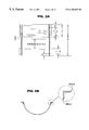
- FIG. 1A is a vertical section through an exemplary tubular form according to the first embodiment of the invention
- FIG. 2A is another vertical section through the tubular form of FIG. 1A;
- FIGS. 1B and 2B are detailed views of components of the form of FIGS. 1 A. and 2 A;
- FIG. 3 is a perspective exploded view showing a portion of the tubular form of FIGS. 1A and 2A on a larger scale;
- FIG. 4 is a side elevation of another embodiment of an assembled form in an upright disposition
- FIG. 5 is a plan view of the form i.e. looking down on the top end;
- FIGS. 6, 7 and 8 are views of one half of the top section of the form of FIG. 4, and FIGS. 9, 10 and 11 are views of the second half of the top section (the two halves not being identical);
- FIGS. 12, 13 and 14 are views of one half of the middle section of the form of FIG. 4, and FIGS. 15, 16 and 17 are views of the second half of the middle section (the two halves again not being identical);
- FIGS. 18, 19 and 20 are views of one half of the bottom section of the form of FIG. 4 whose two halves are identical;
- FIG. 21 is a schematic illustration of a mine support, in a coal mine, produced according to the invention.
- a tubular form indicated generally by numeral 1 (see FIGS. 1A, 1 B, and 3 in particular) comprises a corrugated steel tube 2 divided in a vertical plane into two halves 4 and 6 . Built into half 4 is a slight overhang 5 which is shown in FIGS. 1B and 3.
- Angle irons 8 and 10 are welded to each of the halves 4 and 6 respectively and further angle irons 12 and 14 are welded to the angle irons 8 and 10 respectively.
- the angle irons have a plurality of holes spaced apart at regular intervals. Slotted pins, only one of which is shown at 19 , may be inserted through aligned holes 16 and 18 and held in place by a wedge 20 inserted in the slot (not shown) in the pin 19 . Alternatively the wedges themselves may be slotted and can be inserted into each other.
- FIGS. 4 and 5 An alternative embodiment of the form is illustrated in FIGS. 4 and 5.
- FIGS. 6 to 20 show the details of the three sections and the halves of each section making up the form.
- the assembled form 1 a shown in FIG. 4 comprises or consists of three sections: a top section 30 , middle section 32 and bottom section 34 .
- Each section is made up of two halves which, when the form is assembled and upright, meet in a vertical plane.
- Each section 30 , 32 , 34 utilizes four angle irons to join its respective halves together.
- the angle irons that come into contact with each other when the halves of any section are joined are mirror images of each other.
- the angle iron welded to one side of one half of any section is the mirror image of the angle iron welded to the other side of the same half.
- each section has two pieces of two different angle irons bringing the total to four, and the angle irons used on either half are identical to those used on the other half.
- Angle irons 38 and 40 are welded to one half of the top section 30 and are used to join the two halves together. Angle irons 38 and 40 meet angle irons 39 and 41 respectively. The latter two angle irons are shown in FIG. 5 . All the angle irons are similar to those shown in perspective in FIG. 3 and have a plurality of holes (not shown) spaced apart along their length at regular intervals. Wedges similar to those shown in FIG. 3 hold the irons together when their holes are aligned.
- An angle iron 36 which is longer than angle irons 38 and 40 is welded to the top section 30 and overlaps but is not welded to middle section 32 .
- Middle section 32 has an angle iron 37 welded thereto which meets angle iron 36 and provides a connection which is adjustable to vary the height of the assembled form.
- the two halves of the middle section 32 are joined by angle irons 44 and 45 .
- angle irons 50 and 51 and 53 and 55 The two halves of the bottom section 34 are held together by angle irons 50 and 51 and 53 and 55 , the latter two being shown in FIG. 5 .
- FIGS. 6 to 8 and 9 to 11 gives the dimensions of the top section and the angle irons 36 , 38 , 39 , 40 and 41 . It can be seen that angle iron 40 is offset by 0.75 inches (shown FIG. 8 ).
- FIGS. 12 to 14 and 15 to 17 give the dimensions of the middle section 32 and the angle irons 44 , 45 , 47 and 49 and show that the angle irons are offset by 0.5 inches.
- FIGS. 18 to 20 give the dimensions of the bottom section 34 and the angle irons 50 , 51 , 53 and 55 from which it can be seen that the angle irons are flush with the wall of the form.
- the structures described above may be used in a method of installing a mine support in a coal mine, the support being removable by cutting with a coal shearer, the method comprising: (i) locating in a mine a form (e.g. 1 ) where it is desired to provide support for the mine, the form being composed of a plurality of engaging parts (e.g. 4 , 6 ) shaped to produce a pillar 60 (see FIG.
- the method may further comprise (v) cutting through the pillar 60 and bag 62 of yieldable material and removing same, and (vi) reusing the parts (e.g. 4 , 6 ) of the form after removal from the pillar 60 to make a second pillar.
- a form 1 approximately 4 feet in diameter
- the form 1 is assembled at the point where the mine support is required and its height adjusted to leave a space at the top of the support for the installation of a bag 62 containing a yieldable support material.
- a bag (not shown) to receive the cementitious material is then inserted in the form.
- a mixture comprising 600 pounds/cubic yard of Type 1 ⁇ 2 Portland cement, 1600 pounds/cubic yard of Type F flyash and 833 pounds per cubic yard of water was pumped into the bag from the surface to fill the volume of the form.
- the cement flyash is allowed to set and it take the shape of the form.
- the form 1 is dismantled and removed to expose the newly cast pillar approximately 10 feet in height.
- the minimum 28 day strength of the pillar is 2000 pounds per square inch.
- a bag 62 containing Tekset mixed with water is placed between the top of the pillar and the roof 61 of the mine and allowed to set.
- the form 1 is reassembled at a second location and used again.
- coal shearer is used to cut through the bag 62 of yieldable grout and the cementitious pillar 60 both of which are then removed.
- the mine support being composed of flyash and cement
- the cement and flyash are inexpensive but can typically provide about 2,000 tons of roof support
- the forms being composed of overlapping sections, are adjustable to varying mine heights
- the forms are readily removable; thereby permitting the cementitious pillar to be cut and the forms to be reused
- the cuttable mine supports are more quickly removed than the prior art methods involving a wooden crib
- the complete assembly of cementitious pillar and yieldable bag provides a high strength yet yieldable support.
Abstract
Description
Claims (6)
Priority Applications (1)
| Application Number | Priority Date | Filing Date | Title |
|---|---|---|---|
| US09/249,788 US6196635B1 (en) | 1998-02-17 | 1999-02-16 | Method of installation of cuttable mine support |
Applications Claiming Priority (2)
| Application Number | Priority Date | Filing Date | Title |
|---|---|---|---|
| US7494098P | 1998-02-17 | 1998-02-17 | |
| US09/249,788 US6196635B1 (en) | 1998-02-17 | 1999-02-16 | Method of installation of cuttable mine support |
Publications (1)
| Publication Number | Publication Date |
|---|---|
| US6196635B1 true US6196635B1 (en) | 2001-03-06 |
Family
ID=26756245
Family Applications (1)
| Application Number | Title | Priority Date | Filing Date |
|---|---|---|---|
| US09/249,788 Expired - Fee Related US6196635B1 (en) | 1998-02-17 | 1999-02-16 | Method of installation of cuttable mine support |
Country Status (1)
| Country | Link |
|---|---|
| US (1) | US6196635B1 (en) |
Cited By (10)
| Publication number | Priority date | Publication date | Assignee | Title |
|---|---|---|---|---|
| US20040240948A1 (en) * | 2003-05-27 | 2004-12-02 | Harbaugh William L. | Mine prop |
| US20060086885A1 (en) * | 2004-10-27 | 2006-04-27 | Efficient Mining Systems Llc. | Load-bearing pressurized liquid column |
| US20090226264A1 (en) * | 2006-03-28 | 2009-09-10 | Nils Skarbovig | Grout Pack Restraining System |
| WO2009110903A1 (en) * | 2008-03-06 | 2009-09-11 | Heintzmann Corporation | A pumpable cementitious grout system for use in the production of underground roof-support systems and other load-bearing structures |
| US20110262231A1 (en) * | 2010-04-22 | 2011-10-27 | Micon | Pumpable Support with Cladding |
| US8851805B2 (en) | 2012-08-30 | 2014-10-07 | Burrell Mining Products, Inc. | Telescopic mine roof support |
| WO2015000210A1 (en) * | 2013-07-04 | 2015-01-08 | Zhang Nong | Method for processing roof collapse of coal mine roadway by using flexible air bag |
| CN106285722A (en) * | 2016-08-30 | 2017-01-04 | 中铁十局集团第四工程有限公司 | A kind of device preventing tunnel double-lining vault to come to nothing and construction method thereof |
| US9611738B2 (en) | 2014-08-27 | 2017-04-04 | Burrell Mining Products, Inc. | Ventilated mine roof support |
| US9903203B2 (en) | 2014-08-27 | 2018-02-27 | Burrell Mining Products, Inc. | Ventilated mine roof support |
Citations (6)
| Publication number | Priority date | Publication date | Assignee | Title |
|---|---|---|---|---|
| US4277204A (en) * | 1979-09-13 | 1981-07-07 | Bochumer Eisenhutte Heintzmann Gmbh & Co. | Excavation roof support and method of installing the same |
| US4770564A (en) * | 1984-12-03 | 1988-09-13 | Leon Dison | Mining support pillars |
| US4983077A (en) * | 1987-08-26 | 1991-01-08 | Gebhardt & Koenig-Gesteins- Und Tiefbau Gmbh | Method and an apparatus for producing fabric-reinforced lining supports or slender supporting structural units |
| US5288178A (en) | 1991-12-18 | 1994-02-22 | Hl&H Timber Products (Pty) Ltd. | Preload headboard for an elongate prop |
| US5427476A (en) | 1992-03-04 | 1995-06-27 | Hl & H Timber Products (Pty) Ltd. | Mine prop headboard |
| US5435670A (en) | 1992-07-03 | 1995-07-25 | Hl&H Timber Products (Proprietary) Limited | Spacer assembly and method |
-
1999
- 1999-02-16 US US09/249,788 patent/US6196635B1/en not_active Expired - Fee Related
Patent Citations (6)
| Publication number | Priority date | Publication date | Assignee | Title |
|---|---|---|---|---|
| US4277204A (en) * | 1979-09-13 | 1981-07-07 | Bochumer Eisenhutte Heintzmann Gmbh & Co. | Excavation roof support and method of installing the same |
| US4770564A (en) * | 1984-12-03 | 1988-09-13 | Leon Dison | Mining support pillars |
| US4983077A (en) * | 1987-08-26 | 1991-01-08 | Gebhardt & Koenig-Gesteins- Und Tiefbau Gmbh | Method and an apparatus for producing fabric-reinforced lining supports or slender supporting structural units |
| US5288178A (en) | 1991-12-18 | 1994-02-22 | Hl&H Timber Products (Pty) Ltd. | Preload headboard for an elongate prop |
| US5427476A (en) | 1992-03-04 | 1995-06-27 | Hl & H Timber Products (Pty) Ltd. | Mine prop headboard |
| US5435670A (en) | 1992-07-03 | 1995-07-25 | Hl&H Timber Products (Proprietary) Limited | Spacer assembly and method |
Cited By (18)
| Publication number | Priority date | Publication date | Assignee | Title |
|---|---|---|---|---|
| US20040240948A1 (en) * | 2003-05-27 | 2004-12-02 | Harbaugh William L. | Mine prop |
| US6910834B2 (en) * | 2003-05-27 | 2005-06-28 | Burrell Mining Products, Inc. | Mine prop |
| US20060086885A1 (en) * | 2004-10-27 | 2006-04-27 | Efficient Mining Systems Llc. | Load-bearing pressurized liquid column |
| US7232103B2 (en) * | 2004-10-27 | 2007-06-19 | Efficient Mining Systems Llc | Load-bearing pressurized liquid column |
| US20090226264A1 (en) * | 2006-03-28 | 2009-09-10 | Nils Skarbovig | Grout Pack Restraining System |
| US8021083B2 (en) | 2006-03-28 | 2011-09-20 | Skarboevig Nils Mittet | Grout pack assembly |
| US7789593B2 (en) * | 2006-03-28 | 2010-09-07 | Skarboevig Nils Mittet | Grout pack restraining system |
| US20100284752A1 (en) * | 2006-03-28 | 2010-11-11 | Skarboevig Nils Mittet | Grout pack assembly |
| US20110174194A1 (en) * | 2008-03-06 | 2011-07-21 | Duncan Hird | pumpable cementitious grout system for use in the production of underground roof-support systems and other load-bearing structures |
| WO2009110903A1 (en) * | 2008-03-06 | 2009-09-11 | Heintzmann Corporation | A pumpable cementitious grout system for use in the production of underground roof-support systems and other load-bearing structures |
| US20110262231A1 (en) * | 2010-04-22 | 2011-10-27 | Micon | Pumpable Support with Cladding |
| US8851804B2 (en) * | 2010-04-22 | 2014-10-07 | Micon | Pumpable support with cladding |
| US8851805B2 (en) | 2012-08-30 | 2014-10-07 | Burrell Mining Products, Inc. | Telescopic mine roof support |
| US9347316B2 (en) | 2012-08-30 | 2016-05-24 | Burrell Mining Products, Inc. | Telescopic mine roof support |
| WO2015000210A1 (en) * | 2013-07-04 | 2015-01-08 | Zhang Nong | Method for processing roof collapse of coal mine roadway by using flexible air bag |
| US9611738B2 (en) | 2014-08-27 | 2017-04-04 | Burrell Mining Products, Inc. | Ventilated mine roof support |
| US9903203B2 (en) | 2014-08-27 | 2018-02-27 | Burrell Mining Products, Inc. | Ventilated mine roof support |
| CN106285722A (en) * | 2016-08-30 | 2017-01-04 | 中铁十局集团第四工程有限公司 | A kind of device preventing tunnel double-lining vault to come to nothing and construction method thereof |
Similar Documents
| Publication | Publication Date | Title |
|---|---|---|
| Landriault | Backfill in underground mining. | |
| US6196635B1 (en) | Method of installation of cuttable mine support | |
| US4340254A (en) | Method of mining heavy coal seams in two or more benches | |
| US4770708A (en) | Method of disposing of mining tailings | |
| AU2017388776B2 (en) | Mine anti-explosion trapezoidal sealing wall and construction method therefor | |
| GB2177389A (en) | Filling and solidifying grout slurry in coal pit | |
| US4174135A (en) | Underground formed wall single-entry mining method | |
| DE3413602A1 (en) | Method of re-packing the hollow spaces of the caved debris | |
| JP2007308882A (en) | Lightweight embankment structure | |
| US3469405A (en) | Mine water barrier | |
| JPH0828200A (en) | Filling of space part | |
| EP0351105B1 (en) | Backfilling in mines | |
| RU2164297C2 (en) | Process of filling of worked-out space while developing kimberlite pipe by powered mining complex in rising stratum and gear to conduct filling operation | |
| CN110952998A (en) | Supporting method for fault broken roof | |
| Palarski | Design of backfill as support in Polish coal mines | |
| RU2013549C1 (en) | Method for artificial interhorizontal pillar building by mining steep and inclined formations | |
| US3885395A (en) | Underground mining arch gateway system | |
| RU2055990C1 (en) | Method for making of safety gateside pack | |
| RU2675118C1 (en) | Method for hardening hydraulic stowage mass | |
| SU771347A1 (en) | Method of filling-up excavated area at shield system of mining | |
| SU691578A1 (en) | Method of filling a space after mining | |
| TW311957B (en) | The improving method for weak foundation | |
| SU787659A1 (en) | Method of mining mineral deposits | |
| SU989931A1 (en) | Method of filling chamber worked-out space | |
| Andromalos et al. | Subsidence control by high volume grouting |
Legal Events
| Date | Code | Title | Description |
|---|---|---|---|
| AS | Assignment |
Owner name: FOSROC INTERNATIONAL LIMITED, ENGLAND Free format text: ASSIGNMENT OF ASSIGNORS INTEREST;ASSIGNORS:ROHALY, A.J.;MILLS, PETER S.;REEL/FRAME:009836/0089 Effective date: 19990311 |
|
| FEPP | Fee payment procedure |
Free format text: PAYOR NUMBER ASSIGNED (ORIGINAL EVENT CODE: ASPN); ENTITY STATUS OF PATENT OWNER: LARGE ENTITY |
|
| FPAY | Fee payment |
Year of fee payment: 4 |
|
| AS | Assignment |
Owner name: MINOVA INTERNATIONAL LIMITED, UNITED KINGDOM Free format text: CHANGE OF NAME;ASSIGNOR:FOSROC MINING INTERNATIONAL LIMITED;REEL/FRAME:017251/0585 Effective date: 20030211 Owner name: FOSROC MINING INTERNATIONAL LIMITED, UNITED KINGDO Free format text: ASSIGNMENT OF ASSIGNORS INTEREST;ASSIGNOR:FOSROC INTERNATIONAL LIMITED;REEL/FRAME:017251/0579 Effective date: 20020809 Owner name: MINOVA INTERNATIONAL LIMITED, UNITED KINGDOM Free format text: CHANGE OF NAME;ASSIGNOR:FOSROC MINING INTERNATIONAL LIMITED;REEL/FRAME:017275/0196 Effective date: 20030211 Owner name: FOSROC MINING INTERNATIONAL LIMITED, UNITED KINGDO Free format text: ASSIGNMENT OF ASSIGNORS INTEREST;ASSIGNOR:FOSROC INTERNATIONAL LIMITED;REEL/FRAME:017251/0573 Effective date: 20020809 |
|
| AS | Assignment |
Owner name: FOSROC MINING INTERNATIONAL LIMITED, UNITED KINGDO Free format text: ASSIGNMENT OF ASSIGNORS INTEREST;ASSIGNOR:FOSROC INTERNATIONAL LIMITED;REEL/FRAME:017198/0040 Effective date: 20020809 Owner name: MINOVA INTERNATIONAL LIMITED, UNITED KINGDOM Free format text: CHANGE OF NAME;ASSIGNOR:FOSROC MINING INTERNATIONAL LIMITED;REEL/FRAME:017198/0102 Effective date: 20030211 |
|
| AS | Assignment |
Owner name: FOSROC MINING INTERNATIONAL LIMITED, UNITED KINGDO Free format text: CORRECTIVE ASSIGNMENT TO CORRECT THE 6196636 SHOULD HAVE BEEN 6196635 PREVIOUSLY RECORDED ON REEL 017251 FRAME 0579;ASSIGNOR:FOSROC INTERNATIONAL LIMITED;REEL/FRAME:017297/0239 Effective date: 20020809 Owner name: MINOVA INTERNATIONAL LIMITED, UNITED KINGDOM Free format text: CORRECTIVE ASSIGNMENT TO CORRECT THE 6196636 SHOULD HAVE BEEN 6196635 PREVIOUSLY RECORDED ON REEL 017251 FRAME 0585;ASSIGNOR:FOSROC MINING INTERNATIONAL LIMITED;REEL/FRAME:017297/0254 Effective date: 20030211 Owner name: MINOVA INTERNATIONAL LIMITED, UNITED KINGDOM Free format text: CORRECTIVE ASSIGNMENT TO CORRECT THE 6196636 SHOULD HAVE BEEN 6196635 PREVIOUSLY RECORDED ON REEL 017275 FRAME 0196;ASSIGNOR:FOSROC MINING INTERNATIONAL LIMITED;REEL/FRAME:017297/0256 Effective date: 20030211 |
|
| AS | Assignment |
Owner name: FORSROC MINING INTERNATIONAL LIMITED, UNITED KINGD Free format text: DOCUMENT RE-RECORDED TO CORRECT ERRORS CONTAINED IN PROPERTY NUMBER 6196636. DOCUMENT PREVIOUSLY RECORDED ON REEL 6196636 FRAME 6196635.;ASSIGNOR:FOSROC INTERNATIONAL LIMITED;REEL/FRAME:017336/0643 Effective date: 20020809 |
|
| CC | Certificate of correction | ||
| FPAY | Fee payment |
Year of fee payment: 8 |
|
| FEPP | Fee payment procedure |
Free format text: PAYOR NUMBER ASSIGNED (ORIGINAL EVENT CODE: ASPN); ENTITY STATUS OF PATENT OWNER: LARGE ENTITY Free format text: PAYER NUMBER DE-ASSIGNED (ORIGINAL EVENT CODE: RMPN); ENTITY STATUS OF PATENT OWNER: LARGE ENTITY |
|
| REMI | Maintenance fee reminder mailed | ||
| LAPS | Lapse for failure to pay maintenance fees | ||
| STCH | Information on status: patent discontinuation |
Free format text: PATENT EXPIRED DUE TO NONPAYMENT OF MAINTENANCE FEES UNDER 37 CFR 1.362 |
|
| FP | Lapsed due to failure to pay maintenance fee |
Effective date: 20130306 |