US6173855B1 - Tank closing device for a filler neck of a container - Google Patents
Tank closing device for a filler neck of a container Download PDFInfo
- Publication number
- US6173855B1 US6173855B1 US08/911,237 US91123797A US6173855B1 US 6173855 B1 US6173855 B1 US 6173855B1 US 91123797 A US91123797 A US 91123797A US 6173855 B1 US6173855 B1 US 6173855B1
- Authority
- US
- United States
- Prior art keywords
- closing device
- dogs
- socket elements
- tank
- filler neck
- Prior art date
- Legal status (The legal status is an assumption and is not a legal conclusion. Google has not performed a legal analysis and makes no representation as to the accuracy of the status listed.)
- Expired - Lifetime
Links
Images


Classifications
-
- B—PERFORMING OPERATIONS; TRANSPORTING
- B60—VEHICLES IN GENERAL
- B60K—ARRANGEMENT OR MOUNTING OF PROPULSION UNITS OR OF TRANSMISSIONS IN VEHICLES; ARRANGEMENT OR MOUNTING OF PLURAL DIVERSE PRIME-MOVERS IN VEHICLES; AUXILIARY DRIVES FOR VEHICLES; INSTRUMENTATION OR DASHBOARDS FOR VEHICLES; ARRANGEMENTS IN CONNECTION WITH COOLING, AIR INTAKE, GAS EXHAUST OR FUEL SUPPLY OF PROPULSION UNITS IN VEHICLES
- B60K15/00—Arrangement in connection with fuel supply of combustion engines or other fuel consuming energy converters, e.g. fuel cells; Mounting or construction of fuel tanks
- B60K15/03—Fuel tanks
- B60K15/04—Tank inlets
- B60K15/0406—Filler caps for fuel tanks
-
- Y—GENERAL TAGGING OF NEW TECHNOLOGICAL DEVELOPMENTS; GENERAL TAGGING OF CROSS-SECTIONAL TECHNOLOGIES SPANNING OVER SEVERAL SECTIONS OF THE IPC; TECHNICAL SUBJECTS COVERED BY FORMER USPC CROSS-REFERENCE ART COLLECTIONS [XRACs] AND DIGESTS
- Y10—TECHNICAL SUBJECTS COVERED BY FORMER USPC
- Y10S—TECHNICAL SUBJECTS COVERED BY FORMER USPC CROSS-REFERENCE ART COLLECTIONS [XRACs] AND DIGESTS
- Y10S220/00—Receptacles
- Y10S220/32—Radiator cap
-
- Y—GENERAL TAGGING OF NEW TECHNOLOGICAL DEVELOPMENTS; GENERAL TAGGING OF CROSS-SECTIONAL TECHNOLOGIES SPANNING OVER SEVERAL SECTIONS OF THE IPC; TECHNICAL SUBJECTS COVERED BY FORMER USPC CROSS-REFERENCE ART COLLECTIONS [XRACs] AND DIGESTS
- Y10—TECHNICAL SUBJECTS COVERED BY FORMER USPC
- Y10S—TECHNICAL SUBJECTS COVERED BY FORMER USPC CROSS-REFERENCE ART COLLECTIONS [XRACs] AND DIGESTS
- Y10S220/00—Receptacles
- Y10S220/33—Gasoline tank cap
Definitions
- the invention relates to a tank closing device for a filler neck of a container, in particular of an operating liquid or fuel tank of a transportable work tool such as a disk grinder, a motorised chain saw, an independent cutting tool or similar.
- a closing device for a radiator is known from U.S. Pat. No. 3,027,043.
- a closing member is biassed against the filler neck by a spring and a sealing member is arranged between the closing member and the filler neck.
- the spring biassing the closing member is braced against a closing cap which can be secured on the filler neck by means of a bayonet fitting.
- the closing cap has two radial shoulders, which are used for handling purposes when opening or closing the cap. These shoulders can be used to apply increased torque.
- a design which provides only two oppositely lying locking members for the bayonet fastening causes the filler cap to be tilted transversely, which means that the force applied to the filler cap is very uneven. This can cause the closing member to lift at a point on the circumference of the filler neck so that a momentary look is caused in this manner.
- the object of the present invention is to provide a tank closing device for a filler neck of a container of the aforementioned kind, which is easy to operate even if the design is restricted in terms of space, as well as functionally safe and provides a reliable seal under the most varied of operating conditions.
- the closing cap having a top face and a gripping member projecting upwardly from the top face;
- the bayonet fitting comprising at least three socket elements at a circumferential surface of the closure cap or the filler neck and comprising at least three dogs cooperating with the at least three socket elements and arranged on an opposing circumferential surface of the closing cap or the filler neck;
- socket elements or the dogs or both the socket elements and the dogs are unevenly distributed over the circumferential surface, respectively.
- At least one of the dogs has a circumferential length that is different from a circumferential length of another one of the dogs.
- At least one of the socket elements has a circumferential length that is different from a circumferential length of another one of the socket elements.
- Diametrically opposed ones of the dogs are of identical design.
- Diametrically opposed ones of the socket elements are of identical design.
- a spacing between three of the dogs is such that a first spacing between a first and a second one of the dogs extends over an angle of 58° and a second spacing between a second and a third one of the dogs extends over an angle of 72°.
- the dogs have a circumferential length of 25°.
- Two of the socket elements have a circumferential length of 53°.
- Two of the socket elements have a circumferential length of 65°.
- a spacing between two adjacent ones of the socket elements is 30°.
- Two of the socket elements have an end stop at a rearward end thereof in a closing direction of the bayonet closure.
- the socket elements have a run-in slope at a forward end thereof in a closing direction of the bayonet closure, further have a section of maximum height adjacent to the run-in slopes, and further have a bearing section, having a height reduced relative to the section of maximum height, positioned adjacent to the section of maximum height.
- Two of the socket elements have an end stop at a rearward end thereof in a closing direction of the bayonet closure, wherein the end stops have an incline at a side thereof facing an adjacent one of the socket elements.
- the gripping member comprises a first and second diametrically opposed shoulders, the shoulders having an orifice at front ends thereof.
- the closing cap is beaker-shaped and has a bottom comprising a mounting fixture for securing the closing member.
- the mounting fixture is comprised of a plurality of ring segments having free ends with radial shoulders.
- the closing member has an end face snap-connected to the mounting fixture.
- the tank closing device may further comprise a sealing membrane positioned concentrically to the closing member, the sealing membrane sealingly resting on the closing cap and an annular surface of the filler neck.
- the filler neck is an annular body adaptable to the container.
- the filler neck has an internal diameter and a portion for guiding the closing member, wherein the portion has a length of 0.4 times the internal diameter.
- the main advantages of the invention reside in the fact that by arranging a pushing member on the top face of the closing cap, it is not necessary to allow for any space for the structural design other than that of the circumferential surface of the closing cap since there are at least three dogs and socket elements, an even distribution of forces is guaranteed without any tendency to tilt laterally. Due to the fact that the socket elements and/or the dogs are disposed in an uneven distribution around the circumferential surface, the closing cap can only be positioned at a turning angle relative to the median longitudinal axis of the filler neck such that the gripping member assumes a predetermined direction relative to the container or the transportable work tool when the tank closing device is shut. This means that the tank closing device can not be opened unwittingly because when closed, the gripping member does not provide a gripping surface which can be operated in the turning direction.
- the uneven layout of the dogs and socket elements relative to the circumferential surface can be achieved simply by making at least one of the spacing distances between two respective dogs in the circumferential direction different in size from another spacing distance.
- varying the lengths of the socket elements can be used as a means of producing an uneven layout, in which case an advantage can be gained by giving one of the socket elements or dogs in the circumferential direction a different length from another of the socket elements or dogs.
- socket elements and dogs are provided. This being the case, it is advantageous to use a distribution such that socket elements or dogs lying opposite one another are of the same design.
- the desired unevenness is then provided by two differing sections, each arranged in a respective half circumference.
- a preferred embodiment of this design is one in which a distance of approximately 58° is provided between two successive dogs and the subsequent distance is then approximately 72°, whilst the dogs extend over an angle of approximately 25°.
- the socket elements are purposely designed to be of different lengths, so that two socket elements extend over an angle of approximately 53° and the other two socket elements over an angle of approximately 65°. The distances between two successive socket elements will then be approximately 30°.
- two of the socket elements are provided with end stops at their rear ends in the direction in which the bayonet fitting is fastened.
- the socket elements also have a run-in slope at their front ends in the closing direction.
- a section of maximum height adjoins the run-in slope of the socket elements, following which is a bearing section of a lesser height.
- the end stops are provided with an incline, by means of which a component in the direction of closing is imparted to the filler cap as force is applied axially.
- the gripping member is designed to have two diametrically arranged projections having orifices on their front faces.
- the tank closing device In order to ensure that the tank closing device is protected against soiling as much as possible, it is an advantage to embody the tank closing device as of a beaker shape and its cylindrical section overlaps the filler neck.
- a mounting fixture for the closing member is provided on the base of the filler cap, this mounting fixture consisting of several annular segments with radial projections arranged on their free ends. The closing member is so designed that it can be located in the mounting fixture by one of its end faces.
- a sealing membrane is provided concentrically in the closing member and lies against the filler cap on one side and against an annular surface of the filler neck on the other to form a seal.
- the filler neck may be provided on the container in the form of an adjustable ring, which means, for example, that the container can be manufactured without regard for the exact configuration of the filler neck.
- This also provides a filler neck that will be of standard design and can be used for containers of different designs.
- the closing member is inserted in the filler neck over a specific length. This will prevent the possibility of crooked positioning, which could be detrimental to the sealing capability. It is deemed to be particularly appropriate for the filler neck to be of a length which is some 0.4 times the internal diameter of the filler neck.
- FIG. 1 is a longitudinal section through a tank closing device
- FIG. 2 is a longitudinal section representing a rotation about 90°
- FIG. 3 is a perspective view of the filler neck
- FIG. 4 is a longitudinal section through the filler neck of FIG. 3,
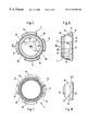
- FIG. 5 is a view from above of the filler neck of FIG. 4,
- FIG. 6 is a view in the direction of the arrow VI of FIG. 5,
- FIG. 7 is a view in the direction of the arrow VII in FIG. 6,
- FIG. 8 is a section of the filler neck with a socket element
- FIG. 9 is a side view of the closing cap
- FIG. 10 is a section along the line X—X of FIG. 9,
- FIG. 11 is a section along the line XI—XI of FIG. 9,
- FIG. 12 is a section along the line XII—XII of FIG. 9,
- FIG. 13 shows a second embodiment of a closing cap in a view corresponding to FIG. 11,
- FIG. 14 shows in a view corresponding to FIG. 7 a second embodiment of a filler neck for use with the closing cap of FIG. 13,
- FIG. 15 shows in a view corresponding to FIG. 3 a third embodiment of a filler neck having dogs arranged thereat,
- FIG. 16 shows in a view corresponding to FIG. 10 a third embodiment of a closing cap having socket elements for cooperation with the filler neck of FIG. 15 .
- FIGS. 1 and 2 show an axial section through a tank closing device 1 , which has a filler neck 2 with a closing member 3 housed therein.
- the closing member 3 has a radial flange 23 , in front of which a sealing ring 4 is arranged, resting on a sealing surface 5 of the filler neck 2 .
- a closing cap 6 Extending across the filler neck 2 and the closing member 3 is a closing cap 6 , which is essentially of a beaker-shaped design and has on its base 7 a mounting fixture 14 in which the closing member 3 is mounted by a longitudinal sliding action.
- an end face 15 of the closing member 3 shaped to form a radial collar 21 , projects into the mounting fixture 14 , which is provided with radial shoulders 22 directed inwards.
- the closing member 3 is of a beaker-shaped design and has a compression spring 8 arranged between its base 24 and the base 7 of the closing cap 6 , which biasses the closing member 3 and in turn the sealing ring 4 against the sealing surface 5 of the filler neck 2 .
- the cylindrical section of the closing cap 6 overlaps a radial shoulder 25 of the filler neck 2 and the closing member 3 is positioned fully protected in the filler neck 2 .
- the manner in which the closing cap 6 is fastened on the filler neck 2 by means of a bayonet fitting will be explained below with reference to FIGS. 3 to 12 .
- a sealing membrane 16 Arranged between the base 7 of the closing cap 6 and an annular surface 17 of the filler neck 2 is a sealing membrane 16 , which provides a tight fit at both the base 7 of the closing cap and against the annular surface 17 of the filler neck 2 , irrespective of any axial displacement between the closing member 3 and the closing cap 6 .
- a gripping member 9 which, in the embodiment illustrated, is in the form of two shoulders 10 arranged in the vicinity of the circumferential edge. Orifices 11 are provided in the shoulders 10 , so as to reduce the amount of material required for manufacture.
- a flexible element 18 Secured to the lower face of the base 24 of the closing member 3 by means of a clip connector 19 is a flexible element 18 , which may consist of a braided cord with synthetic ends suitable for use with the clip connector. The other end of the flexible element 18 is secured by means of a clip connector 19 * in a corresponding receiving means in the internal wall of the container.
- a shackle which could move within the container could also be provided at this end in order to prevent any slipping movement out of the filler neck 2 .
- FIG. 3 shows a perspective view of the filler neck 2 , which consists of a annular body 26 with two first socket elements 12 and two second socket elements 13 arranged on the mantle surface.
- the two first socket elements 12 are arranged diametrically opposite one another and the second socket elements 13 are arranged likewise.
- the socket elements 12 and 13 are used to provide a bayonet fitting for the matching dogs provided on the closing cap 6 , whose design will be described in more detail with reference to FIGS. 9 to 12 .
- a spacing 20 for inserting the dogs provided on the closing cap 6 , which then engage the socket elements 12 and 13 coming into contact with bearing sections 28 when the closing cap 6 is turned.
- FIG. 4 shows an axial section through the filler neck 2 , whose annular body 26 has an annular surface 17 at the upper end. Adjacent to this annular surface 17 are the first socket elements 12 , on the underside of which the bearing section 28 is provided.
- the internal contour of the annular body 26 is a conical section 29 used for inserting the closing member. Adjoining this conical section 29 is the sealing surface 5 , which acts as a mounting surface for the sealing ring.
- the sealing surface 5 describes a cylindrical section 30 , extending preferably over an axial length L, which is about 0.4 times the diameter D of the cylindrical section 30 .
- FIG. 5 shows a view from above of the filler neck 2 illustrated in FIG. 4 .
- two first socket elements 12 are arranged exactly diametrically opposite one another on the annular body 6 ; likewise, two second socket elements 13 lie diametrically opposite one another.
- This drawing also illustrates the fact that the first socket elements extend over a smaller arc angle ⁇ 1 than the second socket elements extending over the larger arc angle ⁇ 2.
- the angle ⁇ 1 is approximately 53°
- the angle ⁇ 2 is 67°.
- a spacing 20 is provided between each two adjacent socket elements 12 , 13 , these spacings 20 being of essentially the same size and extending over an angle a of approximately 30°.
- the angle between the radial median lines of the spacing distances 20 is 83° at the first socket element 12 and 97° at the second socket element 13 , so that the closing cap 6 can be positioned on the filler neck in two defined positions only. Since the angle about which the closing cap is rotated about its longitudinal axis is restricted by the end stops 31 shown in FIG. 6 on the socket elements 12 , the closing cap 6 assumes a defined position when the tank closing device is in the closed state, in which the shoulders 10 of the closing cap 6 which form the gripping member 9 are accurately aligned in a predetermined direction.
- FIG. 6 also shows quite clearly that both the first socket element 12 and the second socket element 13 have a run-in slope 32 on their front ends, which is adjoined by a section 33 of maximum height in the closing direction of the bayonet fitting.
- a section 33 of maximum height in the closing direction of the bayonet fitting Arranged after the section 33 is the bearing section 28 , already described, the end of which is defined by the end stop 31 .
- the end stop 31 On its side delimiting with the spacing 20 to the subsequent socket element, the end stop 31 has an incline 34 .
- FIG. 7 shows a view in the direction of the arrow VII of FIG. 6 .
- the reference numbers used for common parts are the same as those used for FIGS. 5 and 6.
- FIG. 8 shows a cut-out of the annular body 26 with a side view of the first socket element 12 in its full extension with a run-in slope 32 , a section 33 of maximum height and a bearing section 28 .
- the socket element 12 has an incline 34 * at the rear end of the bearing section 28 .
- FIG. 9 illustrates a side view of the closing cap 6 , from which it can be seen that several spherical depressions 35 are arranged at the circumferential edge of the closing cap, which provides an improved grip on the closing cap 6 .
- the shoulders 10 forming the gripping member 9 are located on the top face of the closing cap 6 .
- FIG. 10 illustrates a section along the line X—X of FIG. 9 .
- the mounting fixture 14 on the base 7 consists of several ring segments 36 , on the front ends of which the inwardly directed radial shoulders 22 are provided.
- the mounting fixture 14 formed by these ring segments 36 permits a temporary flaring so that the radial collar formed on the end face 15 of the closing member 3 can be inserted in the mounting fixture.
- dogs 37 Located on the internal mantle area at the open edge of the cylindrical section of the closing cap 6 are dogs 37 which are provided with run-in slopes 38 at their front ends in the direction in which the bayonet fitting is closed. The dogs 37 engage behind the socket elements on the filler neck.
- FIG. 11, illustrating a section along the line XI—XI of FIG. 9, shows that six ring segments 36 are provided in total to form the mounting fixture 14 .
- Eight spherical depressions 35 are evenly distributed across the outer circumference of the closing cap 6 .
- four dogs 37 are arranged on the inner circumferential surface of the closing cap 6 , such that each of the dogs extends over an angle ⁇ of approximately 25°.
- the distances between two adjacent dogs 37 are different so that two diametrically opposite distances 40 extend over an angle ⁇ 1 of approximately 58°.
- the distances 41 respectively offset from the distances 40 extend over an angle ⁇ 2 of approximately 72°.
- the distribution of angles between the radial median lines of the dogs 37 alternates between 83° and 97°, matching the corresponding angle layout of the filler neck as illustrated in FIG. 5 .
- FIG. 12 shows a section along the line XII—XII of FIG. 11, in which this section is taken through the dog 37 .
- the side 39 of the dog 37 facing the base 7 of the closing member 6 rests on the bearing section 28 of the socket element 12 or 13 of the filler neck 2 illustrated in FIGS. 3 to 7 .
- FIGS. 13 and 14 shows another embodiment of a tank closure with three dogs 37 at the closing cap 6 and three cooperating socket elements 12 at the filler neck 2 in views similar to FIGS. 11 and 7, respectively.
- FIGS. 15 and 16 show an embodiment with a reverse arrangement of the dogs and the socket elements, i.e., FIG. 15 shows the filler neck 2 with dogs 37 on the torus 26 and FIG. 16 shows the cap 6 with socket elements 12 , 13 .
Abstract
Description
Claims (46)
Applications Claiming Priority (2)
| Application Number | Priority Date | Filing Date | Title |
|---|---|---|---|
| DE29614077U DE29614077U1 (en) | 1996-08-15 | 1996-08-15 | Tank cap for a filler neck of a container |
| DE29614077U | 1996-08-15 |
Publications (1)
| Publication Number | Publication Date |
|---|---|
| US6173855B1 true US6173855B1 (en) | 2001-01-16 |
Family
ID=8027820
Family Applications (1)
| Application Number | Title | Priority Date | Filing Date |
|---|---|---|---|
| US08/911,237 Expired - Lifetime US6173855B1 (en) | 1996-08-15 | 1997-08-15 | Tank closing device for a filler neck of a container |
Country Status (4)
| Country | Link |
|---|---|
| US (1) | US6173855B1 (en) |
| DE (1) | DE29614077U1 (en) |
| FR (1) | FR2752396B1 (en) |
| GB (1) | GB2316398B (en) |
Cited By (12)
| Publication number | Priority date | Publication date | Assignee | Title |
|---|---|---|---|---|
| US6568553B2 (en) * | 2000-06-07 | 2003-05-27 | Toyoda Gosei Co., Ltd. | Tank cap and tank cap apparatus |
| US20040217117A1 (en) * | 2003-05-01 | 2004-11-04 | Chien-Ping Lien | Cover for the great water outlet of a water bag |
| US20050121454A1 (en) * | 2003-12-04 | 2005-06-09 | Asteer Co., Ltd. | Fuel cap |
| US20050233801A1 (en) * | 2001-10-15 | 2005-10-20 | Baerlocher Anthony J | Gaming device having a re-triggering symbol bonus scheme |
| US20070170187A1 (en) * | 2006-01-20 | 2007-07-26 | Bemis Manufacturing Company | Modular ratchet cap |
| US20070170186A1 (en) * | 2006-01-20 | 2007-07-26 | Elesa S.P.A. | Vent cap for oil tanks of machines and the like equipped with splash guard |
| CN102748092A (en) * | 2012-07-24 | 2012-10-24 | 潍柴动力股份有限公司 | Oil feeding pipe assembly and engine comprising same |
| CN102865121A (en) * | 2012-09-20 | 2013-01-09 | 潍坊倍力汽车零部件有限公司 | Oil filling pipe assembly for engine |
| USD692738S1 (en) | 2011-06-30 | 2013-11-05 | Hellermanntyton Corporation | Cable tie tensioning and cut-off tool |
| US8955556B2 (en) | 2011-06-30 | 2015-02-17 | Hellermanntyton Corporation | Cable tie tensioning and cut-off tool |
| US9103501B1 (en) * | 2013-07-10 | 2015-08-11 | Cai YANG | Gas cylinder safety purge and anchor system |
| US10259604B2 (en) | 2014-12-12 | 2019-04-16 | Hellermanntyton Corporation | Compound tension and calibration mechanism for cable tie tensioning and cut-off tool |
Families Citing this family (2)
| Publication number | Priority date | Publication date | Assignee | Title |
|---|---|---|---|---|
| EP3632730B1 (en) | 2018-10-01 | 2021-05-26 | Andreas Stihl AG & Co. KG | Closure cap for an operating liquid tank |
| CN109340378B (en) * | 2018-11-12 | 2023-12-01 | 中国船舶重工集团公司第七一九研究所 | Automatic packing sealing device compresses tightly |
Citations (6)
| Publication number | Priority date | Publication date | Assignee | Title |
|---|---|---|---|---|
| US3027043A (en) | 1959-05-22 | 1962-03-27 | Eaton Mfg Co | Closure device |
| US4162021A (en) | 1974-09-30 | 1979-07-24 | Stant Manufacturing Company, Inc. | Pressure-vacuum relief fuel tank cap with roll-over safety valve feature |
| US4162741A (en) * | 1977-04-29 | 1979-07-31 | National Presto Industries, Inc. | Pressure cooker |
| US4185751A (en) * | 1978-07-31 | 1980-01-29 | Stant Manufacturing Company, Inc. | Radiator cap |
| US5165565A (en) * | 1991-06-04 | 1992-11-24 | Andreas Stihl | Closure for a vessel |
| US5169015A (en) * | 1992-02-20 | 1992-12-08 | Stant Corporation | Vehicle radiator cap with auxiliary vacuum seal |
Family Cites Families (2)
| Publication number | Priority date | Publication date | Assignee | Title |
|---|---|---|---|---|
| JPS5937476Y2 (en) * | 1976-03-25 | 1984-10-17 | 日本ラヂエーター株式会社 | fuel tank lid |
| US5443175A (en) * | 1994-04-19 | 1995-08-22 | Crown Cork & Seal Company, Inc. | Resealable closure device |
-
1996
- 1996-08-15 DE DE29614077U patent/DE29614077U1/en not_active Expired - Lifetime
-
1997
- 1997-07-01 FR FR9708266A patent/FR2752396B1/en not_active Expired - Lifetime
- 1997-07-21 GB GB9715330A patent/GB2316398B/en not_active Expired - Lifetime
- 1997-08-15 US US08/911,237 patent/US6173855B1/en not_active Expired - Lifetime
Patent Citations (6)
| Publication number | Priority date | Publication date | Assignee | Title |
|---|---|---|---|---|
| US3027043A (en) | 1959-05-22 | 1962-03-27 | Eaton Mfg Co | Closure device |
| US4162021A (en) | 1974-09-30 | 1979-07-24 | Stant Manufacturing Company, Inc. | Pressure-vacuum relief fuel tank cap with roll-over safety valve feature |
| US4162741A (en) * | 1977-04-29 | 1979-07-31 | National Presto Industries, Inc. | Pressure cooker |
| US4185751A (en) * | 1978-07-31 | 1980-01-29 | Stant Manufacturing Company, Inc. | Radiator cap |
| US5165565A (en) * | 1991-06-04 | 1992-11-24 | Andreas Stihl | Closure for a vessel |
| US5169015A (en) * | 1992-02-20 | 1992-12-08 | Stant Corporation | Vehicle radiator cap with auxiliary vacuum seal |
Cited By (29)
| Publication number | Priority date | Publication date | Assignee | Title |
|---|---|---|---|---|
| US6913162B2 (en) | 2000-06-07 | 2005-07-05 | Toyoda Gosei Co., Ltd. | Tank cap and tank cap apparatus |
| US6568553B2 (en) * | 2000-06-07 | 2003-05-27 | Toyoda Gosei Co., Ltd. | Tank cap and tank cap apparatus |
| US20120289310A1 (en) * | 2001-10-15 | 2012-11-15 | Igt | Gaming device having a re-triggering symbol bonus scheme |
| US9799168B2 (en) * | 2001-10-15 | 2017-10-24 | Igt | Gaming device having a re-triggering symbol bonus scheme |
| US20050233801A1 (en) * | 2001-10-15 | 2005-10-20 | Baerlocher Anthony J | Gaming device having a re-triggering symbol bonus scheme |
| US20170004682A1 (en) * | 2001-10-15 | 2017-01-05 | Igt | Gaming device having a re-triggering symbol bonus scheme |
| US9449471B2 (en) | 2001-10-15 | 2016-09-20 | Igt | Gaming device having a re-triggering symbol bonus scheme |
| US8753190B2 (en) * | 2001-10-15 | 2014-06-17 | Igt | Gaming device having a re-triggering symbol bonus scheme |
| US20040217117A1 (en) * | 2003-05-01 | 2004-11-04 | Chien-Ping Lien | Cover for the great water outlet of a water bag |
| US7484636B2 (en) * | 2003-12-04 | 2009-02-03 | Asteer Co., Ltd. | Fuel cap with high sealing properties |
| US20050121454A1 (en) * | 2003-12-04 | 2005-06-09 | Asteer Co., Ltd. | Fuel cap |
| US20070170186A1 (en) * | 2006-01-20 | 2007-07-26 | Elesa S.P.A. | Vent cap for oil tanks of machines and the like equipped with splash guard |
| US8074334B2 (en) * | 2006-01-20 | 2011-12-13 | Bemis Manufacturing Company | Modular ratchet cap |
| US20070170187A1 (en) * | 2006-01-20 | 2007-07-26 | Bemis Manufacturing Company | Modular ratchet cap |
| US7959026B2 (en) * | 2006-01-20 | 2011-06-14 | Elesa S.P.A. | Vent cap for oil tanks of machines and the like equipped with splash guard |
| USD732361S1 (en) | 2011-06-30 | 2015-06-23 | Hellermanntyton Corporation | Cable tie tensioning and cut-off tool handle |
| US9550590B2 (en) | 2011-06-30 | 2017-01-24 | Hellermann Tyton Corporation | Cable tie tensioning and cut-off tool |
| US9694924B2 (en) | 2011-06-30 | 2017-07-04 | Hellermanntyton Corporation | Cable tie tensioning and cut-off tool |
| US8960241B2 (en) | 2011-06-30 | 2015-02-24 | Hellermanntyton Corporation | Cable tie tensioning and cut-off tool |
| USD692738S1 (en) | 2011-06-30 | 2013-11-05 | Hellermanntyton Corporation | Cable tie tensioning and cut-off tool |
| USD755029S1 (en) | 2011-06-30 | 2016-05-03 | Hellermanntyton Corporation | Cable tie tensioning and cut-off tool knob |
| US9394067B2 (en) | 2011-06-30 | 2016-07-19 | Hellermanntyton Corporation | Cable tie tensioning and cut-off tool |
| US9394068B2 (en) | 2011-06-30 | 2016-07-19 | Hellermann Tyton Corporation | Cable tie tensioning and cut-off tool |
| US8955556B2 (en) | 2011-06-30 | 2015-02-17 | Hellermanntyton Corporation | Cable tie tensioning and cut-off tool |
| CN102748092A (en) * | 2012-07-24 | 2012-10-24 | 潍柴动力股份有限公司 | Oil feeding pipe assembly and engine comprising same |
| CN102865121B (en) * | 2012-09-20 | 2015-04-15 | 潍坊倍力汽车零部件有限公司 | Oil filling pipe assembly for engine |
| CN102865121A (en) * | 2012-09-20 | 2013-01-09 | 潍坊倍力汽车零部件有限公司 | Oil filling pipe assembly for engine |
| US9103501B1 (en) * | 2013-07-10 | 2015-08-11 | Cai YANG | Gas cylinder safety purge and anchor system |
| US10259604B2 (en) | 2014-12-12 | 2019-04-16 | Hellermanntyton Corporation | Compound tension and calibration mechanism for cable tie tensioning and cut-off tool |
Also Published As
| Publication number | Publication date |
|---|---|
| GB2316398B (en) | 1998-07-01 |
| DE29614077U1 (en) | 1996-09-26 |
| FR2752396B1 (en) | 2000-04-14 |
| GB9715330D0 (en) | 1997-09-24 |
| FR2752396A1 (en) | 1998-02-20 |
| GB2316398A (en) | 1998-02-25 |
Similar Documents
| Publication | Publication Date | Title |
|---|---|---|
| US6173855B1 (en) | Tank closing device for a filler neck of a container | |
| KR0145297B1 (en) | Fluid conduit coupling apparatus | |
| US6079582A (en) | Tank closure for the fill opening of a fuel tank | |
| US5111838A (en) | Dunnage bag air valve and coupling | |
| US4807847A (en) | Valved oil pan plug | |
| CA1137060A (en) | Faucet extender | |
| US6209745B1 (en) | Pop up flush-mount gas cap | |
| US4823835A (en) | Universal swivel having a driving handle and valve means | |
| US5379796A (en) | Air pump head capable of engaging tire air valve in twist-locking manner | |
| US6138709A (en) | Overfill protection device | |
| CA2157158C (en) | Assembly for providing a passage for liquid between a first member and a second member | |
| US6109467A (en) | Closure cap for an operating fluid container | |
| EP1790517B1 (en) | Misfuelling prevention device | |
| AU777274B2 (en) | Automatic shut-off device for a valve for compressed or liquefied gases | |
| US20150041697A1 (en) | Shut-Off Valve | |
| US5407175A (en) | Flow valve having rotatable annular flange | |
| US5255704A (en) | Leakproof hydraulic valve | |
| DE7212499U (en) | FILL AND DRAIN VALVE, IN PARTICULAR FOR GUARANTEE CUSHIONS | |
| US4609004A (en) | Aircraft safety fuel tank | |
| GB2050483A (en) | Vehicle Filling Connections and Lids Therefor | |
| US5966788A (en) | Spring vice for tensioning coil springs with two pressure plates | |
| GB2174375A (en) | Closure valve-beer keys | |
| US2165639A (en) | Valve | |
| US20040103942A1 (en) | Valve lock mechanism | |
| US20060086736A1 (en) | Fuel cap and filler tube combination and method therefor |
Legal Events
| Date | Code | Title | Description |
|---|---|---|---|
| AS | Assignment |
Owner name: STIHL, ANDREAS, GERMANY Free format text: ASSIGNMENT OF ASSIGNORS INTEREST;ASSIGNOR:STARK, THOMAS;REEL/FRAME:008754/0699 Effective date: 19970731 Owner name: ANDREAS STIHL, GERMANY Free format text: ASSIGNMENT OF ASSIGNORS INTEREST;ASSIGNOR:STARK, THOMAS;REEL/FRAME:008754/0699 Effective date: 19970731 |
|
| AS | Assignment |
Owner name: ANDREAS STIHL AG. & CO., GERMANY Free format text: CHANGE OF NAME;ASSIGNOR:ANDREAS STIHL AG & CO.;REEL/FRAME:010366/0301 Effective date: 19980319 |
|
| FEPP | Fee payment procedure |
Free format text: PAYOR NUMBER ASSIGNED (ORIGINAL EVENT CODE: ASPN); ENTITY STATUS OF PATENT OWNER: LARGE ENTITY |
|
| STCF | Information on status: patent grant |
Free format text: PATENTED CASE |
|
| FPAY | Fee payment |
Year of fee payment: 4 |
|
| FPAY | Fee payment |
Year of fee payment: 8 |
|
| FPAY | Fee payment |
Year of fee payment: 12 |