US6166520A - Intercell bussing system for battery pack - Google Patents
Intercell bussing system for battery pack Download PDFInfo
- Publication number
- US6166520A US6166520A US09/491,241 US49124100A US6166520A US 6166520 A US6166520 A US 6166520A US 49124100 A US49124100 A US 49124100A US 6166520 A US6166520 A US 6166520A
- Authority
- US
- United States
- Prior art keywords
- lid
- cells
- electrical
- intercell
- carrying member
- Prior art date
- Legal status (The legal status is an assumption and is not a legal conclusion. Google has not performed a legal analysis and makes no representation as to the accuracy of the status listed.)
- Expired - Fee Related
Links
Images
Classifications
-
- H—ELECTRICITY
- H02—GENERATION; CONVERSION OR DISTRIBUTION OF ELECTRIC POWER
- H02J—CIRCUIT ARRANGEMENTS OR SYSTEMS FOR SUPPLYING OR DISTRIBUTING ELECTRIC POWER; SYSTEMS FOR STORING ELECTRIC ENERGY
- H02J7/00—Circuit arrangements for charging or depolarising batteries or for supplying loads from batteries
- H02J7/0042—Circuit arrangements for charging or depolarising batteries or for supplying loads from batteries characterised by the mechanical construction
- H02J7/0045—Circuit arrangements for charging or depolarising batteries or for supplying loads from batteries characterised by the mechanical construction concerning the insertion or the connection of the batteries
-
- H—ELECTRICITY
- H01—ELECTRIC ELEMENTS
- H01M—PROCESSES OR MEANS, e.g. BATTERIES, FOR THE DIRECT CONVERSION OF CHEMICAL ENERGY INTO ELECTRICAL ENERGY
- H01M50/00—Constructional details or processes of manufacture of the non-active parts of electrochemical cells other than fuel cells, e.g. hybrid cells
- H01M50/20—Mountings; Secondary casings or frames; Racks, modules or packs; Suspension devices; Shock absorbers; Transport or carrying devices; Holders
- H01M50/204—Racks, modules or packs for multiple batteries or multiple cells
- H01M50/207—Racks, modules or packs for multiple batteries or multiple cells characterised by their shape
- H01M50/209—Racks, modules or packs for multiple batteries or multiple cells characterised by their shape adapted for prismatic or rectangular cells
-
- H—ELECTRICITY
- H01—ELECTRIC ELEMENTS
- H01M—PROCESSES OR MEANS, e.g. BATTERIES, FOR THE DIRECT CONVERSION OF CHEMICAL ENERGY INTO ELECTRICAL ENERGY
- H01M50/00—Constructional details or processes of manufacture of the non-active parts of electrochemical cells other than fuel cells, e.g. hybrid cells
- H01M50/50—Current conducting connections for cells or batteries
- H01M50/502—Interconnectors for connecting terminals of adjacent batteries; Interconnectors for connecting cells outside a battery casing
- H01M50/505—Interconnectors for connecting terminals of adjacent batteries; Interconnectors for connecting cells outside a battery casing comprising a single busbar
-
- H—ELECTRICITY
- H01—ELECTRIC ELEMENTS
- H01M—PROCESSES OR MEANS, e.g. BATTERIES, FOR THE DIRECT CONVERSION OF CHEMICAL ENERGY INTO ELECTRICAL ENERGY
- H01M50/00—Constructional details or processes of manufacture of the non-active parts of electrochemical cells other than fuel cells, e.g. hybrid cells
- H01M50/50—Current conducting connections for cells or batteries
- H01M50/569—Constructional details of current conducting connections for detecting conditions inside cells or batteries, e.g. details of voltage sensing terminals
-
- H—ELECTRICITY
- H01—ELECTRIC ELEMENTS
- H01M—PROCESSES OR MEANS, e.g. BATTERIES, FOR THE DIRECT CONVERSION OF CHEMICAL ENERGY INTO ELECTRICAL ENERGY
- H01M50/00—Constructional details or processes of manufacture of the non-active parts of electrochemical cells other than fuel cells, e.g. hybrid cells
- H01M50/50—Current conducting connections for cells or batteries
- H01M50/572—Means for preventing undesired use or discharge
- H01M50/574—Devices or arrangements for the interruption of current
-
- H—ELECTRICITY
- H01—ELECTRIC ELEMENTS
- H01M—PROCESSES OR MEANS, e.g. BATTERIES, FOR THE DIRECT CONVERSION OF CHEMICAL ENERGY INTO ELECTRICAL ENERGY
- H01M50/00—Constructional details or processes of manufacture of the non-active parts of electrochemical cells other than fuel cells, e.g. hybrid cells
- H01M50/50—Current conducting connections for cells or batteries
-
- Y—GENERAL TAGGING OF NEW TECHNOLOGICAL DEVELOPMENTS; GENERAL TAGGING OF CROSS-SECTIONAL TECHNOLOGIES SPANNING OVER SEVERAL SECTIONS OF THE IPC; TECHNICAL SUBJECTS COVERED BY FORMER USPC CROSS-REFERENCE ART COLLECTIONS [XRACs] AND DIGESTS
- Y02—TECHNOLOGIES OR APPLICATIONS FOR MITIGATION OR ADAPTATION AGAINST CLIMATE CHANGE
- Y02E—REDUCTION OF GREENHOUSE GAS [GHG] EMISSIONS, RELATED TO ENERGY GENERATION, TRANSMISSION OR DISTRIBUTION
- Y02E60/00—Enabling technologies; Technologies with a potential or indirect contribution to GHG emissions mitigation
- Y02E60/10—Energy storage using batteries
Definitions
- the invention pertains to an intercell buss system for a battery pack and in particular, a system which incorporates inherent safety features.
- intercell buss system comprising:
- a lid having an up and a down position, such that in the down position, the lid covers a portion of the terminals of the cells; further, the lid has a projection thereon;
- a current carrying member located on the projection of the lid such that when the lid is in the down position electrical current can pass from one cell to the other through the current carrying member which acts as an intercell buss and when the lid is in the up position, no current can pass through the current carrying member.
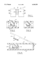
- FIG. 1 is a top sectional perspective view of the intercell buss contact between a pair of cells.
- FIG. 2 is a sectional view taken along line 2--2 of FIG. 1 showing the intercell buss connection.
- FIG. 3 is a side sectional view taken along line 3--3 of FIG. 1 showing the intercell sense connection.
- FIG. 4 is taken along line 4--4 of FIG. 2 and is a sectional perspective view of a the battery pack in a closed position and in outline in the open position where the cover is hinged to the battery tray.
- the present invention is directed towards an intercell buss system 10 showing at least a pair of electrical cells 12 and 14. While only two cells are shown, the number can increase depending on the desired end use of the battery pack.
- the buss 16 overlaps and connects the cell terminal ends 12A and 14A.
- the buss is an electrically conductive material such as aluminum or its alloys or copper based materials and is retained in the lid projection 20 by retaining members 23.
- the battery cells 12 and 14 fit within a tray 22 and are retained in position by upright members 24 and 26.
- the lid 18 may be hinged about member 28. Obviously any technique for a lid may be used besides a hinge such as a freely moveable top and the like.
- the lid 18 When the lid 18 closes about the battery pack it makes an electrical connection through buss 16. Simultaneously, it makes an electrical connection with lead member 30.
- the lead member permits sensing of the connection with an external lead or circuit (not shown).
- the battery pack material can be made up of a variety of materials such as metal or plastic, such as polypropylene, polyethylene, ABS and the like.
- the battery pack assembly it is desirable to insert the cells along a path perpendicular to the axis of the cell.
- the axis runs through the cell from one terminal to the other. This development allows this cell path during assembly.
- the cells may be placed into a battery pack tray 22 and captured by a connector 16.
- the buss connector 16 is integrated into a lid or cover as is shown in the Figures.
- the cover or lid 18 provides a contact point, a hold down force and interconnects the two cells simultaneously.
- the device shown herein allows the intercell bussing to be mounted in the lid so that if the lid is on the pack, the pack will be disabled when the lid is opened.
- connection to the sense lead 30 is made with the same part. At the same time that there is a power connection there is contact with multiple contact points.
- the battery has particular applicability to the lithium polymer batteries, such as 42 volt battery pack system. Obviously, however, it is applicable to a wide variety of electrical cells such as conventional lead acid cells. In addition, it would be applicable for other secondary or rechargeable batteries as well as primary batteries and fuel cells where such intercell connection is desirable.
- bussing system described herein is modular in design. One can add battery packs to fit the desired voltage, e.g. 12 volts to 48 to 144 volts, and the like.
- the battery pack and the intercell connection permits easy assembly into strings or packs without tools being necessary.
- the cell terminals 12 and 14 can be the same as for a side-by-side cell orientation since no customization of the cell is required for a flat pack application.
- This bussing system allows for universal cell terminals.
- the size of the terminals can vary and accordingly can permit high current capacity as well as low resistance.
- the invention as described herein reduces tolerance stack up and tolerates minor misalignment of the cells. This can be handled by virtue of the geometric arrangement and the size of the intercell connector 16.
- the connector 16 and the sense lead 30 arrangement as shown in the drawings herein, the connector and lead can be keyed to provide positive rejection of improperly oriented cells.
- the mechanical relationship between the buss and the cell terminals will permit a detection of whether the cell has been inserted correctly.
Landscapes
- Chemical & Material Sciences (AREA)
- Chemical Kinetics & Catalysis (AREA)
- Electrochemistry (AREA)
- General Chemical & Material Sciences (AREA)
- Engineering & Computer Science (AREA)
- Power Engineering (AREA)
- Battery Mounting, Suspending (AREA)
- Connection Of Batteries Or Terminals (AREA)
Abstract
Description
Claims (8)
Priority Applications (2)
| Application Number | Priority Date | Filing Date | Title |
|---|---|---|---|
| US09/491,241 US6166520A (en) | 2000-01-25 | 2000-01-25 | Intercell bussing system for battery pack |
| DE10103117A DE10103117A1 (en) | 2000-01-25 | 2001-01-24 | Inter-cell bus connection system for a battery pack |
Applications Claiming Priority (1)
| Application Number | Priority Date | Filing Date | Title |
|---|---|---|---|
| US09/491,241 US6166520A (en) | 2000-01-25 | 2000-01-25 | Intercell bussing system for battery pack |
Publications (1)
| Publication Number | Publication Date |
|---|---|
| US6166520A true US6166520A (en) | 2000-12-26 |
Family
ID=23951357
Family Applications (1)
| Application Number | Title | Priority Date | Filing Date |
|---|---|---|---|
| US09/491,241 Expired - Fee Related US6166520A (en) | 2000-01-25 | 2000-01-25 | Intercell bussing system for battery pack |
Country Status (2)
| Country | Link |
|---|---|
| US (1) | US6166520A (en) |
| DE (1) | DE10103117A1 (en) |
Cited By (3)
| Publication number | Priority date | Publication date | Assignee | Title |
|---|---|---|---|---|
| US6765247B2 (en) | 2001-10-12 | 2004-07-20 | Intersil Americas, Inc. | Integrated circuit with a MOS structure having reduced parasitic bipolar transistor action |
| US6896995B2 (en) * | 2000-05-25 | 2005-05-24 | Yazaki Corporation | Battery cover |
| CN104428923A (en) * | 2012-07-09 | 2015-03-18 | 矢崎总业株式会社 | Bus bar module |
Citations (3)
| Publication number | Priority date | Publication date | Assignee | Title |
|---|---|---|---|---|
| US4993973A (en) * | 1989-11-20 | 1991-02-19 | Motorola, Inc. | Battery contact |
| US5795675A (en) * | 1994-02-15 | 1998-08-18 | Mag Instrument, Inc. | Battery device |
| US5820406A (en) * | 1996-07-29 | 1998-10-13 | Hetherington; Michael Warnett | Terminal and door latch for battery operated devices |
-
2000
- 2000-01-25 US US09/491,241 patent/US6166520A/en not_active Expired - Fee Related
-
2001
- 2001-01-24 DE DE10103117A patent/DE10103117A1/en not_active Ceased
Patent Citations (3)
| Publication number | Priority date | Publication date | Assignee | Title |
|---|---|---|---|---|
| US4993973A (en) * | 1989-11-20 | 1991-02-19 | Motorola, Inc. | Battery contact |
| US5795675A (en) * | 1994-02-15 | 1998-08-18 | Mag Instrument, Inc. | Battery device |
| US5820406A (en) * | 1996-07-29 | 1998-10-13 | Hetherington; Michael Warnett | Terminal and door latch for battery operated devices |
Cited By (4)
| Publication number | Priority date | Publication date | Assignee | Title |
|---|---|---|---|---|
| US6896995B2 (en) * | 2000-05-25 | 2005-05-24 | Yazaki Corporation | Battery cover |
| US6765247B2 (en) | 2001-10-12 | 2004-07-20 | Intersil Americas, Inc. | Integrated circuit with a MOS structure having reduced parasitic bipolar transistor action |
| CN104428923A (en) * | 2012-07-09 | 2015-03-18 | 矢崎总业株式会社 | Bus bar module |
| EP2871693A4 (en) * | 2012-07-09 | 2015-12-09 | Yazaki Corp | Bus bar module |
Also Published As
| Publication number | Publication date |
|---|---|
| DE10103117A1 (en) | 2001-11-22 |
Similar Documents
| Publication | Publication Date | Title |
|---|---|---|
| RU2355069C2 (en) | Modular storage battery | |
| JP3061097B2 (en) | Battery electrical connector | |
| US8183831B2 (en) | Battery pack | |
| EP2538469B1 (en) | Battery pack | |
| US4435486A (en) | Quick disconnect battery installation and charging system | |
| US20050140338A1 (en) | Lead member and secondary battery module with the same | |
| KR20170054878A (en) | Battery module and battery pack including the same | |
| US8895181B2 (en) | Battery module | |
| KR20060073455A (en) | Sensing board assembly for secondary battery module | |
| EP2064759A1 (en) | Battery module interface | |
| US20100159289A1 (en) | Secondary battery | |
| KR960036165A (en) | battery | |
| US20150137767A1 (en) | Protection apparatus for rechargeable battery | |
| US10541452B2 (en) | Battery pack including circuit board having protruding surface | |
| JP2015202029A (en) | Protective device for secondary battery | |
| US5300372A (en) | Rechargeable cell or cell pack contact configuration | |
| US10079381B2 (en) | Rechargeable battery pack | |
| US6166520A (en) | Intercell bussing system for battery pack | |
| CN107615518A (en) | Battery module and the battery pack including the battery module | |
| US4319178A (en) | Charging system with multiple attachable cellholder modules | |
| US8895183B2 (en) | External terminal assembly including a terminal holder coupled to a protection circuit substrate and battery pack including the same | |
| EP3703178B1 (en) | Battery module | |
| US11524394B2 (en) | Disassembling tool and battery module using disassembling tool | |
| JP2003045383A (en) | Battery pack | |
| US7056619B2 (en) | Chargeable battery for medical diagnostic instruments |
Legal Events
| Date | Code | Title | Description |
|---|---|---|---|
| AS | Assignment |
Owner name: DELPHI TECHNOLOGIES, INC., MICHIGAN Free format text: ASSIGNMENT OF ASSIGNORS INTEREST;ASSIGNORS:WATERS, JOHN EUGENE;HANAUER, BRAD T.;REEL/FRAME:010524/0258;SIGNING DATES FROM 20000111 TO 20000113 |
|
| FPAY | Fee payment |
Year of fee payment: 4 |
|
| AS | Assignment |
Owner name: ENERDEL, INC.,FLORIDA Free format text: ASSIGNMENT OF ASSIGNORS INTEREST;ASSIGNOR:DELPHI TECHNOLOGIES, INC.;REEL/FRAME:015972/0640 Effective date: 20041020 Owner name: ENERDEL, INC., FLORIDA Free format text: ASSIGNMENT OF ASSIGNORS INTEREST;ASSIGNOR:DELPHI TECHNOLOGIES, INC.;REEL/FRAME:015972/0640 Effective date: 20041020 |
|
| FPAY | Fee payment |
Year of fee payment: 8 |
|
| AS | Assignment |
Owner name: BZINFIN S.A., SWITZERLAND Free format text: SECURITY AGREEMENT;ASSIGNORS:ENERDEL, INC.;ENERFUEL, INC.;ENER1, INC.;AND OTHERS;REEL/FRAME:027370/0979 Effective date: 20111116 |
|
| AS | Assignment |
Owner name: ENERFUEL, INC., FLORIDA Free format text: TERMINATION AND RELEASE OF SECURITY INTEREST IN PATENTS;ASSIGNOR:BZINFIN, S.A.;REEL/FRAME:027982/0854 Effective date: 20120330 Owner name: ENERDEL, INC., ILLINOIS Free format text: TERMINATION AND RELEASE OF SECURITY INTEREST IN PATENTS;ASSIGNOR:BZINFIN, S.A.;REEL/FRAME:027982/0854 Effective date: 20120330 Owner name: NANO ENER, INC., FLORIDA Free format text: TERMINATION AND RELEASE OF SECURITY INTEREST IN PATENTS;ASSIGNOR:BZINFIN, S.A.;REEL/FRAME:027982/0854 Effective date: 20120330 Owner name: ENER1, INC., INDIANA Free format text: TERMINATION AND RELEASE OF SECURITY INTEREST IN PATENTS;ASSIGNOR:BZINFIN, S.A.;REEL/FRAME:027982/0854 Effective date: 20120330 |
|
| AS | Assignment |
Owner name: WILMINGTON TRUST, NATIONAL ASSOCIATION, MINNESOTA Free format text: PATENT SECURITY AGREEMENT;ASSIGNORS:ENER1, INC.;ENERDEL, INC.;ENERFUEL, INC.;AND OTHERS;REEL/FRAME:027999/0516 Effective date: 20120330 |
|
| REMI | Maintenance fee reminder mailed | ||
| LAPS | Lapse for failure to pay maintenance fees | ||
| STCH | Information on status: patent discontinuation |
Free format text: PATENT EXPIRED DUE TO NONPAYMENT OF MAINTENANCE FEES UNDER 37 CFR 1.362 |
|
| FP | Lapsed due to failure to pay maintenance fee |
Effective date: 20121226 |