US6152538A - Mechanical locks for wheel covers - Google Patents
Mechanical locks for wheel covers Download PDFInfo
- Publication number
- US6152538A US6152538A US09/062,136 US6213698A US6152538A US 6152538 A US6152538 A US 6152538A US 6213698 A US6213698 A US 6213698A US 6152538 A US6152538 A US 6152538A
- Authority
- US
- United States
- Prior art keywords
- wheel
- cover
- rim
- hub
- protrusion
- Prior art date
- Legal status (The legal status is an assumption and is not a legal conclusion. Google has not performed a legal analysis and makes no representation as to the accuracy of the status listed.)
- Expired - Fee Related
Links
Images

Classifications
-
- B—PERFORMING OPERATIONS; TRANSPORTING
- B60—VEHICLES IN GENERAL
- B60B—VEHICLE WHEELS; CASTORS; AXLES FOR WHEELS OR CASTORS; INCREASING WHEEL ADHESION
- B60B7/00—Wheel cover discs, rings, or the like, for ornamenting, protecting, venting, or obscuring, wholly or in part, the wheel body, rim, hub, or tyre sidewall, e.g. wheel cover discs, wheel cover discs with cooling fins
- B60B7/06—Fastening arrangements therefor
- B60B7/061—Fastening arrangements therefor characterised by the part of the wheels to which the discs, rings or the like are mounted
- B60B7/063—Fastening arrangements therefor characterised by the part of the wheels to which the discs, rings or the like are mounted to the rim
-
- B—PERFORMING OPERATIONS; TRANSPORTING
- B60—VEHICLES IN GENERAL
- B60B—VEHICLE WHEELS; CASTORS; AXLES FOR WHEELS OR CASTORS; INCREASING WHEEL ADHESION
- B60B7/00—Wheel cover discs, rings, or the like, for ornamenting, protecting, venting, or obscuring, wholly or in part, the wheel body, rim, hub, or tyre sidewall, e.g. wheel cover discs, wheel cover discs with cooling fins
- B60B7/01—Rings specially adapted for covering only the wheel rim or the tyre sidewall, e.g. removable tyre sidewall trim rings
-
- B—PERFORMING OPERATIONS; TRANSPORTING
- B60—VEHICLES IN GENERAL
- B60B—VEHICLE WHEELS; CASTORS; AXLES FOR WHEELS OR CASTORS; INCREASING WHEEL ADHESION
- B60B7/00—Wheel cover discs, rings, or the like, for ornamenting, protecting, venting, or obscuring, wholly or in part, the wheel body, rim, hub, or tyre sidewall, e.g. wheel cover discs, wheel cover discs with cooling fins
- B60B7/04—Wheel cover discs, rings, or the like, for ornamenting, protecting, venting, or obscuring, wholly or in part, the wheel body, rim, hub, or tyre sidewall, e.g. wheel cover discs, wheel cover discs with cooling fins built-up of several main parts
-
- B—PERFORMING OPERATIONS; TRANSPORTING
- B60—VEHICLES IN GENERAL
- B60B—VEHICLE WHEELS; CASTORS; AXLES FOR WHEELS OR CASTORS; INCREASING WHEEL ADHESION
- B60B7/00—Wheel cover discs, rings, or the like, for ornamenting, protecting, venting, or obscuring, wholly or in part, the wheel body, rim, hub, or tyre sidewall, e.g. wheel cover discs, wheel cover discs with cooling fins
- B60B7/06—Fastening arrangements therefor
- B60B7/061—Fastening arrangements therefor characterised by the part of the wheels to which the discs, rings or the like are mounted
- B60B7/065—Fastening arrangements therefor characterised by the part of the wheels to which the discs, rings or the like are mounted to the disc
-
- B—PERFORMING OPERATIONS; TRANSPORTING
- B60—VEHICLES IN GENERAL
- B60B—VEHICLE WHEELS; CASTORS; AXLES FOR WHEELS OR CASTORS; INCREASING WHEEL ADHESION
- B60B7/00—Wheel cover discs, rings, or the like, for ornamenting, protecting, venting, or obscuring, wholly or in part, the wheel body, rim, hub, or tyre sidewall, e.g. wheel cover discs, wheel cover discs with cooling fins
- B60B7/06—Fastening arrangements therefor
- B60B7/061—Fastening arrangements therefor characterised by the part of the wheels to which the discs, rings or the like are mounted
- B60B7/066—Fastening arrangements therefor characterised by the part of the wheels to which the discs, rings or the like are mounted to the hub
-
- B—PERFORMING OPERATIONS; TRANSPORTING
- B60—VEHICLES IN GENERAL
- B60B—VEHICLE WHEELS; CASTORS; AXLES FOR WHEELS OR CASTORS; INCREASING WHEEL ADHESION
- B60B7/00—Wheel cover discs, rings, or the like, for ornamenting, protecting, venting, or obscuring, wholly or in part, the wheel body, rim, hub, or tyre sidewall, e.g. wheel cover discs, wheel cover discs with cooling fins
- B60B7/06—Fastening arrangements therefor
- B60B7/12—Fastening arrangements therefor comprising an annular spring or gripping element mounted on the cover
-
- B—PERFORMING OPERATIONS; TRANSPORTING
- B60—VEHICLES IN GENERAL
- B60B—VEHICLE WHEELS; CASTORS; AXLES FOR WHEELS OR CASTORS; INCREASING WHEEL ADHESION
- B60B7/00—Wheel cover discs, rings, or the like, for ornamenting, protecting, venting, or obscuring, wholly or in part, the wheel body, rim, hub, or tyre sidewall, e.g. wheel cover discs, wheel cover discs with cooling fins
- B60B7/16—Anti-theft devices
Definitions
- the invention relates to wheel covers for vehicular wheels. More specifically, the invention relates to a locking mechanism for wheel covers to lock the wheel covers to the vehicular wheels.
- Wheel covers are aesthetic devices used to enhance the look of the wheels to which they are attached. Wheel covers are used because the manufacture, finish and mounting of a wheel cover to a wheel is less expensive than manufacturing a wheel having the same quality finish of a wheel cover. A chrome surface on a wheel cover is an inexpensive alternative to a chrome plated or polished wheel. In addition, wheel covers provide various types of appearances and styling variations, all of which may be combined with a single wheel design. The desirability of wheel covers is, however, directly proportional to the ability to inexpensively attach the wheel covers to the wheel permanently while adding little weight to the overall composite wheel.
- U.S. Pat. No. 5,366,278, issued to Brumfield discloses a snap-on retention device for a wheel cover.
- the snap-on retention device wraps around the wheel rim and extends down along the wheel where a lower arm portion creates a spring-like attachment for a down turned lip which wraps around the wheel rim.
- this device locks the periphery of the wheel cover to the wheel rim of a wheel, it does not lock the wheel cover to the hub area of the wheel.
- the clip is designed such that it is difficult to seal the areas between the wheel and the wheel cover from contaminants because the wheel cover is secured so far from the wheel.
- U.S. Pat. No. 5,509,725, issued to Chiu discloses a wheel cover assembly for wheels wherein the wheel cover includes locating blocks formed directly in the wheel cover. These locating blocks are used to lock the wheel cover to the wheel. The manufacture of the locating blocks increases the cost and weight of the wheel cover because they are formed integral with the wheel cover. Further, the wheel covers must be secured to the wheel in a specific orientation. More specifically, the clips and the locating blocks must be aligned. This adds time and costs to the assembly of a composite wheel. Therefore, there is a need in the art for an inexpensive mechanical lock used to secure a wheel cover to a wheel regardless of the orientation of the wheel cover with respect to the wheel and regardless of the type of wheel being covered.
- a wheel cover assembly covering a wheel having a hub receiving end and an outer rim.
- the wheel cover assembly includes a cover having an inner portion disposed adjacent the hub receiving end and an outer periphery disposed adjacent the outer rim.
- a hub lock secures the cover to the hub receiving portion of the wheel.
- a rim lock secures the cover to the outer rim of the wheel.
- One advantage associated with the invention is the ability to secure a wheel cover to a wheel. Another advantage associated with the invention is the ability to secure a wheel cover to a wheel mechanically. Yet another advantage associated with the invention is the ability to secure a wheel cover to a wheel regardless of the orientation of the wheel cover with respect to the wheel. Still another advantage associated with the invention is the ability to secure a wheel cover to a wheel using a light-weight, inexpensive locking system.
- FIG. 1 is a cross-sectional side view partial cut away of a wheel and tire with the preferred embodiment of the invention securing a wheel cover to the wheel;
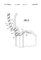
- FIG. 2 is an enlarged view of Section 2 of FIG. 1;
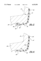
- FIG. 3 is an enlarged view of Section 3 of FIG. 1;
- FIG. 4 is a second embodiment of the invention similar to the embodiment shown in Section 3 of FIG. 1;
- FIG. 5 is a side view partially cut away of a third embodiment of the invention.
- a composite wheel is generally indicated at 10.
- the composite wheel 10 includes a vehicular wheel 12 and a wheel cover 14.
- an alloy wheel is shown representing the vehicular wheel 12, it may be appreciated by those skilled in the art that a steel wheel may also be used for the vehicular wheel 12.
- a tire 16 is seated within the vehicular wheel 12.
- the tire 16 has two tire beads 18, 20, each of which includes a wire cable 22, 24 extending therethrough.
- the vehicular wheel 12 includes a hub receiving end 26 and an outer rim 28.
- the outer rim 28 receives the tire beads 18, 20 therein.
- the hub receiving end 26 receives a wheel hub (not shown) of a motor vehicle.
- a spider 30 extends between the outer rim 28 and the hub receiving end 26.
- the spider 30 may be of any shape or contour as is desired. Typically, the spider 30 has holes extending therethrough.
- the hub receiving end 26 includes a channel or recess 32.
- the channel 32 typically used with the alloy wheel shown in the Figures, will be discussed in greater detail subsequently.
- the wheel cover or cover 14 extends over the spider 30.
- the cover 14 includes an inner portion 34 which is disposed adjacent the hub receiving end 26.
- the cover 14 also includes an outer periphery 36 which is disposed adjacent the outer rim 28.
- the cover 14 includes a protrusion 38 which is located in the inner portion 34 of the cover 14.
- the protrusion 38 is designed to be received by the channel 32 of the vehicular wheel 12.
- the protrusion 38 is spring biased into the channel 32 and provides a mechanical lock for the cover 14 to be secured to the vehicular wheel 12 at the inner portion 34 thereof.
- the protrusion 38 is a hub lock which secures the cover 14 to the hub receiving portion or end 26 of the vehicular wheel 12.
- the cover 14 may extend radially inwardly to cover the hub portion.
- a rim lock secures the cover 14 to the outer rim 28 of the vehicular wheel 12.
- the rim lock 40 includes a rim clasp 42 which engages the outer periphery 36 of the cover 14 and the outer rim 28 of the vehicular wheel 12.
- a similar rim lock as disclosed in U.S. Pat. No. 5,368,370 which is hereby incorporated by reference, may be used in place of the rim lock 40.
- the cover 14 also includes a receiving channel 44 for receiving the rim clasp 42 therein.
- the rim clasp 42 includes a curved end 46 which matingly engages the receiving channel 44 of the cover 14.
- the rim clasp 42 further includes a hook end 48 which extends around the outer rim 28 of the vehicular wheel 12.
- the hook end 48 wraps around a rim engaging portion 50 of the rim clasp 42 to cover the outer rim 28 of the vehicular wheel 12.
- a spring 52 engages the protrusion 38 of the cover 14 to add an additional spring bias force to the force provided by the protrusion 38.
- the spring 52 is circular in cross section.
- the spring 52 is not used in conjunction with the protrusion 38'.
- the protrusion 38' is of sufficient strength to obviate the need of the spring 52.
- a sealant 54, 56 may be placed between the cover 14 and the vehicular wheel 12 to prevent contaminants from collecting therebetween resulting in the reduction of corrosion of the outboard surface 58 of the wheel 12 and the inboard surface 60 of the cover 14.
- the sealant 54, 56 may be located around any opening of the cover 14 and the vehicular wheel 12 as is shown in the Figures. Alternatively, the sealant 54 may cover the entire outboard surface 58 of the wheel 12.
- the sealant 54, 56 may have adhesive qualities inherent in a sealant, the sealant 54, 56 is not required to operate as an adhesive as the rim 40 and hub 38 locks provide the necessary mechanical lock to maintain the wheel cover 14 in an engaged position with the vehicular wheel 12.
- the composite wheel 10' includes a vehicular wheel 12', shown partially cut away and in phantom.
- the wheel cover 14' is secured to the vehicular wheel 12' adjacent the hub receiving end 26' thereof.
- a clip 62 locks or holds the wheel cover 14' to the hub receiving end 26'.
- the clip 62 includes a cover end 64 which is received in a cover recess 66 and a wheel end 68 which abuts a surface 70 of the vehicular wheel 12'.
Landscapes
- Engineering & Computer Science (AREA)
- Mechanical Engineering (AREA)
- Connection Of Plates (AREA)
- Snaps, Bayonet Connections, Set Pins, And Snap Rings (AREA)
- Tires In General (AREA)
- Lock And Its Accessories (AREA)
- Vehicle Body Suspensions (AREA)
Abstract
Description
Claims (9)
Priority Applications (8)
| Application Number | Priority Date | Filing Date | Title |
|---|---|---|---|
| US09/062,136 US6152538A (en) | 1998-04-17 | 1998-04-17 | Mechanical locks for wheel covers |
| DE69919440T DE69919440T2 (en) | 1998-04-17 | 1999-04-12 | Mechanical lock for wheel covers |
| EP99201093A EP0956977B1 (en) | 1998-04-17 | 1999-04-12 | Mechanical locks for wheel covers |
| AT99201093T ATE273801T1 (en) | 1998-04-17 | 1999-04-12 | MECHANICAL LOCKING FOR WHEEL COVERS |
| AU23752/99A AU2375299A (en) | 1998-04-17 | 1999-04-13 | Mechanical locks for wheel covers |
| CA002269101A CA2269101C (en) | 1998-04-17 | 1999-04-15 | Mechanical locks for wheel covers |
| BR9903085-3A BR9903085A (en) | 1998-04-17 | 1999-04-16 | Composite wheel and hubcap set |
| JP11110358A JPH11321203A (en) | 1998-04-17 | 1999-04-19 | Mechanical locking body for wheel cover |
Applications Claiming Priority (1)
| Application Number | Priority Date | Filing Date | Title |
|---|---|---|---|
| US09/062,136 US6152538A (en) | 1998-04-17 | 1998-04-17 | Mechanical locks for wheel covers |
Publications (1)
| Publication Number | Publication Date |
|---|---|
| US6152538A true US6152538A (en) | 2000-11-28 |
Family
ID=22040437
Family Applications (1)
| Application Number | Title | Priority Date | Filing Date |
|---|---|---|---|
| US09/062,136 Expired - Fee Related US6152538A (en) | 1998-04-17 | 1998-04-17 | Mechanical locks for wheel covers |
Country Status (8)
| Country | Link |
|---|---|
| US (1) | US6152538A (en) |
| EP (1) | EP0956977B1 (en) |
| JP (1) | JPH11321203A (en) |
| AT (1) | ATE273801T1 (en) |
| AU (1) | AU2375299A (en) |
| BR (1) | BR9903085A (en) |
| CA (1) | CA2269101C (en) |
| DE (1) | DE69919440T2 (en) |
Cited By (13)
| Publication number | Priority date | Publication date | Assignee | Title |
|---|---|---|---|---|
| WO2003031204A2 (en) * | 2001-10-10 | 2003-04-17 | Lacks Enterprises, Inc. | Wheel and cladding |
| US6609763B1 (en) | 1997-10-31 | 2003-08-26 | Hayes Lemmerz International, Inc. | Vehicle wheel cover retention system and method for producing same |
| US20040095013A1 (en) * | 2002-11-19 | 2004-05-20 | Gerard Philip O. | Center cap for vehicle wheel |
| US6779852B2 (en) * | 2001-04-19 | 2004-08-24 | Lacks Industries, Inc. | Composite wheel assembly and method for producing same |
| US20060055231A1 (en) * | 2002-06-14 | 2006-03-16 | Metcalfe Richard A | Trim for a wheel rim |
| US20060125311A1 (en) * | 2004-12-15 | 2006-06-15 | Jeff Bruce | Center lock wheel cover |
| US7204562B2 (en) | 2002-10-23 | 2007-04-17 | Lacks Enterprises, Inc. | Wheel clad assembly |
| US7393062B1 (en) * | 2004-03-30 | 2008-07-01 | Hayes Lemmerz International, Inc. | Vehicle wheel cover retention system and method for producing same |
| US7448695B1 (en) * | 2005-10-20 | 2008-11-11 | Hayes Lemmerz International, Inc. | Vehicle wheel cover retention system and method for producing same |
| US20110006589A1 (en) * | 2009-07-08 | 2011-01-13 | Hayes Lemmerz International, Inc. | Multi-piece vehicle wheel cover retention system and method for producing same |
| USRE42140E1 (en) | 1998-02-11 | 2011-02-15 | Hayes Lemmerz International, Inc. | Vehicle wheel cover retention system and method for producing same |
| DE102010061623A1 (en) | 2010-01-04 | 2011-07-07 | Hayes Lemmerz International, Inc., Mich. | Multi-part vehicle wheel arrangement and method for its production |
| DE102011051637A1 (en) | 2010-07-12 | 2012-01-12 | Hayes Lemmerz International, Inc. | Multi-part vehicle wheel arrangement and method for its production |
Families Citing this family (2)
| Publication number | Priority date | Publication date | Assignee | Title |
|---|---|---|---|---|
| US6527346B2 (en) * | 2001-07-11 | 2003-03-04 | James Chen | Removable vehicle wheel ring |
| FR3059595B1 (en) * | 2016-12-02 | 2019-05-10 | Peugeot Citroen Automobiles Sa | VEHICLE WHEEL INSERT, WITH SOLIDARIZED ARM (S) TO THE RIM |
Citations (10)
| Publication number | Priority date | Publication date | Assignee | Title |
|---|---|---|---|---|
| US2493001A (en) * | 1943-12-22 | 1950-01-03 | Lyon George Albert | Wheel cover |
| US2497895A (en) * | 1944-01-07 | 1950-02-21 | Lyon George Albert | Wheel cover |
| US2864654A (en) * | 1953-12-21 | 1958-12-16 | Hurd Lock & Mfg Company | Wheel cover |
| US2955685A (en) * | 1958-10-27 | 1960-10-11 | Lyon George Albert | Air circulation wheel structure |
| US2993736A (en) * | 1957-11-12 | 1961-07-25 | Lyon George Albert | Wheel cover |
| DE3704384A1 (en) * | 1987-02-12 | 1988-08-25 | Reinhold Huppert Fa | Wheel for motor vehicles, in particular passenger vehicles |
| EP0310777A1 (en) * | 1987-10-09 | 1989-04-12 | Bayerische Motoren Werke Aktiengesellschaft, Patentabteilung AJ-3 | Vehicle wheel hub cap |
| EP0339513A1 (en) * | 1988-04-27 | 1989-11-02 | Nissan Motor Co., Ltd. | Wheel cover |
| US5597213A (en) * | 1995-06-06 | 1997-01-28 | Lacks Industries, Inc. | Wheel and overlay assembly |
| US5829843A (en) * | 1996-10-28 | 1998-11-03 | Mckechnie Vehicle Components | Wheel applique and lock |
Family Cites Families (7)
| Publication number | Priority date | Publication date | Assignee | Title |
|---|---|---|---|---|
| DE2646419A1 (en) * | 1975-10-23 | 1977-04-28 | James Connell | JEWELRY RING FOR DECORATING VEHICLE WHEELS |
| SE423209B (en) * | 1978-08-08 | 1982-04-26 | Volvo Ab | WHEEL CAP FOR VEHICLE WHEELS |
| US4596425A (en) | 1984-04-24 | 1986-06-24 | Hung Rong Tsan | Plastic wheel cover using retaining ring |
| DE8702166U1 (en) * | 1987-02-12 | 1987-07-02 | Fa. Reinhold Huppert, 3560 Biedenkopf | Wheel for motor vehicles, in particular passenger cars |
| US5366278A (en) | 1992-08-17 | 1994-11-22 | Brumfield John H | Snap-on retention device and system for wheel cover |
| US5368370A (en) | 1993-09-03 | 1994-11-29 | Thompson International | Vehicle wheel construction |
| US5509725A (en) | 1994-11-16 | 1996-04-23 | Mexa Co., Ltd. | Wheel cover assembly for motor vehicles |
-
1998
- 1998-04-17 US US09/062,136 patent/US6152538A/en not_active Expired - Fee Related
-
1999
- 1999-04-12 AT AT99201093T patent/ATE273801T1/en not_active IP Right Cessation
- 1999-04-12 EP EP99201093A patent/EP0956977B1/en not_active Expired - Lifetime
- 1999-04-12 DE DE69919440T patent/DE69919440T2/en not_active Expired - Fee Related
- 1999-04-13 AU AU23752/99A patent/AU2375299A/en not_active Abandoned
- 1999-04-15 CA CA002269101A patent/CA2269101C/en not_active Expired - Fee Related
- 1999-04-16 BR BR9903085-3A patent/BR9903085A/en not_active IP Right Cessation
- 1999-04-19 JP JP11110358A patent/JPH11321203A/en active Pending
Patent Citations (10)
| Publication number | Priority date | Publication date | Assignee | Title |
|---|---|---|---|---|
| US2493001A (en) * | 1943-12-22 | 1950-01-03 | Lyon George Albert | Wheel cover |
| US2497895A (en) * | 1944-01-07 | 1950-02-21 | Lyon George Albert | Wheel cover |
| US2864654A (en) * | 1953-12-21 | 1958-12-16 | Hurd Lock & Mfg Company | Wheel cover |
| US2993736A (en) * | 1957-11-12 | 1961-07-25 | Lyon George Albert | Wheel cover |
| US2955685A (en) * | 1958-10-27 | 1960-10-11 | Lyon George Albert | Air circulation wheel structure |
| DE3704384A1 (en) * | 1987-02-12 | 1988-08-25 | Reinhold Huppert Fa | Wheel for motor vehicles, in particular passenger vehicles |
| EP0310777A1 (en) * | 1987-10-09 | 1989-04-12 | Bayerische Motoren Werke Aktiengesellschaft, Patentabteilung AJ-3 | Vehicle wheel hub cap |
| EP0339513A1 (en) * | 1988-04-27 | 1989-11-02 | Nissan Motor Co., Ltd. | Wheel cover |
| US5597213A (en) * | 1995-06-06 | 1997-01-28 | Lacks Industries, Inc. | Wheel and overlay assembly |
| US5829843A (en) * | 1996-10-28 | 1998-11-03 | Mckechnie Vehicle Components | Wheel applique and lock |
Cited By (24)
| Publication number | Priority date | Publication date | Assignee | Title |
|---|---|---|---|---|
| US6609763B1 (en) | 1997-10-31 | 2003-08-26 | Hayes Lemmerz International, Inc. | Vehicle wheel cover retention system and method for producing same |
| USRE42140E1 (en) | 1998-02-11 | 2011-02-15 | Hayes Lemmerz International, Inc. | Vehicle wheel cover retention system and method for producing same |
| US6779852B2 (en) * | 2001-04-19 | 2004-08-24 | Lacks Industries, Inc. | Composite wheel assembly and method for producing same |
| US6637832B2 (en) * | 2001-10-10 | 2003-10-28 | Lacks Enterprises, Inc. | Wheel and cladding |
| WO2003031204A3 (en) * | 2001-10-10 | 2003-10-30 | Lacks Entpr Inc | Wheel and cladding |
| DE10295236B4 (en) * | 2001-10-10 | 2011-05-12 | Lacks Enterprises, Inc., Grand Rapids | Wheel with fairing |
| WO2003031204A2 (en) * | 2001-10-10 | 2003-04-17 | Lacks Enterprises, Inc. | Wheel and cladding |
| US20060055231A1 (en) * | 2002-06-14 | 2006-03-16 | Metcalfe Richard A | Trim for a wheel rim |
| US7204562B2 (en) | 2002-10-23 | 2007-04-17 | Lacks Enterprises, Inc. | Wheel clad assembly |
| US6969124B2 (en) | 2002-11-19 | 2005-11-29 | Lacks Enterprises, Inc. | Center cap for vehicle wheel |
| US20040095013A1 (en) * | 2002-11-19 | 2004-05-20 | Gerard Philip O. | Center cap for vehicle wheel |
| US7393062B1 (en) * | 2004-03-30 | 2008-07-01 | Hayes Lemmerz International, Inc. | Vehicle wheel cover retention system and method for producing same |
| US20060125311A1 (en) * | 2004-12-15 | 2006-06-15 | Jeff Bruce | Center lock wheel cover |
| US7300116B2 (en) | 2004-12-15 | 2007-11-27 | Mckechnie Vehicle Components (Usa), Inc. | Center lock wheel cover |
| US7448695B1 (en) * | 2005-10-20 | 2008-11-11 | Hayes Lemmerz International, Inc. | Vehicle wheel cover retention system and method for producing same |
| JP2011016518A (en) * | 2009-07-08 | 2011-01-27 | Hayes Lemmerz Internatl Inc | Multi-piece vehicle wheel cover holding system and method for producing the same |
| DE102010017785A1 (en) | 2009-07-08 | 2011-01-13 | Hayes Lemmerz International, Inc., Northville | Cover for a vehicle wheel and method for its manufacture |
| US20110006589A1 (en) * | 2009-07-08 | 2011-01-13 | Hayes Lemmerz International, Inc. | Multi-piece vehicle wheel cover retention system and method for producing same |
| US8052223B2 (en) * | 2009-07-08 | 2011-11-08 | Hayes Lemmerz International, Inc. | Multi-piece vehicle wheel cover retention system and method for producing same |
| DE102010061623A1 (en) | 2010-01-04 | 2011-07-07 | Hayes Lemmerz International, Inc., Mich. | Multi-part vehicle wheel arrangement and method for its production |
| US20110163593A1 (en) * | 2010-01-04 | 2011-07-07 | Heck Thomas E | Multi-piece vehicle wheel cover retention system and method for producing same |
| US8162406B2 (en) | 2010-01-04 | 2012-04-24 | Hayes Lemmerz International, Inc. | Multi-piece vehicle wheel cover retention system and method for producing same |
| DE102011051637A1 (en) | 2010-07-12 | 2012-01-12 | Hayes Lemmerz International, Inc. | Multi-part vehicle wheel arrangement and method for its production |
| US8449043B2 (en) | 2010-07-12 | 2013-05-28 | Hayes Lemmerz International, Inc. | Multi-piece vehicle wheel cover retention system and method for producing same |
Also Published As
| Publication number | Publication date |
|---|---|
| EP0956977A2 (en) | 1999-11-17 |
| EP0956977A3 (en) | 2002-03-27 |
| AU2375299A (en) | 1999-10-28 |
| CA2269101C (en) | 2003-06-03 |
| DE69919440D1 (en) | 2004-09-23 |
| EP0956977B1 (en) | 2004-08-18 |
| DE69919440T2 (en) | 2005-09-08 |
| ATE273801T1 (en) | 2004-09-15 |
| CA2269101A1 (en) | 1999-10-17 |
| BR9903085A (en) | 2001-10-30 |
| JPH11321203A (en) | 1999-11-24 |
Similar Documents
| Publication | Publication Date | Title |
|---|---|---|
| US6152538A (en) | Mechanical locks for wheel covers | |
| EP0932508B1 (en) | Wheel applique and lock | |
| US5498130A (en) | Cooling fan mounting system | |
| US7748887B2 (en) | Positive locking light fixture with faceplate | |
| US6238007B1 (en) | Retaining article for wheel ornamentation and method of making | |
| US6499377B1 (en) | Vehicle steering wheel | |
| US20120043803A1 (en) | Hub cover attachment assembly | |
| US5031953A (en) | Visor bracket | |
| US4083606A (en) | Wheel cover locking device | |
| US6402254B1 (en) | Retaining article for wheel ornamentation including integral support | |
| US6457781B1 (en) | Retaining article for wheel ornamentation | |
| US4516706A (en) | Spare tire cover | |
| US7300116B2 (en) | Center lock wheel cover | |
| US5765865A (en) | Mounting structure for steering wheel | |
| CA2210904C (en) | Integral steering wheel and airbag module | |
| US4063783A (en) | Retainer for wheel trim | |
| US4844551A (en) | Wheel trim for automotive vehicle | |
| US5253928A (en) | Attachment of kinetic wheel balancers | |
| JP3724357B2 (en) | Vehicle wheel decoration | |
| US5509725A (en) | Wheel cover assembly for motor vehicles | |
| US5273345A (en) | Wheel weight channel conceal band | |
| US4749234A (en) | Anti-rotation/retention clip for wheel trim | |
| KR200168203Y1 (en) | Roof-rack assembly of a car | |
| JP3261818B2 (en) | Seat belt buckle cover mounting structure | |
| US20230219365A1 (en) | Motor-vehicle wheel-rim protector |
Legal Events
| Date | Code | Title | Description |
|---|---|---|---|
| AS | Assignment |
Owner name: MCKECHNIE VEHICLE COMPONENTS (USA), INC., MICHIGAN Free format text: ASSIGNMENT OF ASSIGNORS INTEREST;ASSIGNORS:FERRISS, DAVID B.;JOHNSON, DAVID H.;ISRAEL, RAJAKUMAR;REEL/FRAME:009116/0904;SIGNING DATES FROM 19980410 TO 19980413 |
|
| AS | Assignment |
Owner name: DEUTSCHE BANK AG LONDON, UNITED KINGDOM Free format text: SECURITY AGREEMENT;ASSIGNORS:MCKECHNIE INVESTMENTS, INC.;MCKECHNIE PLASTIC COMPONENTS (MN);WESTERN SKY INDUSTRIES, LLC A DELAWARE LIMITED LIABILITY COMPANY;AND OTHERS;REEL/FRAME:011511/0570 Effective date: 20001120 |
|
| FEPP | Fee payment procedure |
Free format text: PAT HOLDER NO LONGER CLAIMS SMALL ENTITY STATUS, ENTITY STATUS SET TO UNDISCOUNTED (ORIGINAL EVENT CODE: STOL); ENTITY STATUS OF PATENT OWNER: LARGE ENTITY Free format text: PAT HOLDER CLAIMS SMALL ENTITY STATUS, ENTITY STATUS SET TO SMALL (ORIGINAL EVENT CODE: LTOS); ENTITY STATUS OF PATENT OWNER: LARGE ENTITY |
|
| CC | Certificate of correction | ||
| FEPP | Fee payment procedure |
Free format text: PAT HOLDER NO LONGER CLAIMS SMALL ENTITY STATUS, ENTITY STATUS SET TO UNDISCOUNTED (ORIGINAL EVENT CODE: STOL); ENTITY STATUS OF PATENT OWNER: LARGE ENTITY |
|
| REFU | Refund |
Free format text: REFUND - SURCHARGE FOR LATE PAYMENT, SMALL ENTITY (ORIGINAL EVENT CODE: R2554); ENTITY STATUS OF PATENT OWNER: LARGE ENTITY Free format text: REFUND - SURCHARGE, PETITION TO ACCEPT PYMT AFTER EXP, UNINTENTIONAL (ORIGINAL EVENT CODE: R2551); ENTITY STATUS OF PATENT OWNER: LARGE ENTITY |
|
| REMI | Maintenance fee reminder mailed | ||
| FPAY | Fee payment |
Year of fee payment: 4 |
|
| SULP | Surcharge for late payment | ||
| AS | Assignment |
Owner name: ARGER ENTERPRISES, INC., NEVADA Free format text: RELEASE AND TERMINATION OF INTELLECTUAL PROPERTY SECURITY AGREEMENT;ASSIGNOR:DEUTSCHE BANK AG LONDON;REEL/FRAME:016116/0482 Effective date: 20050526 Owner name: HARTWELL CORPORATION, CALIFORNIA Free format text: RELEASE AND TERMINATION OF INTELLECTUAL PROPERTY SECURITY AGREEMENT;ASSIGNOR:DEUTSCHE BANK AG LONDON;REEL/FRAME:016116/0482 Effective date: 20050526 Owner name: WESTERN SKY INDUSTRIES, LLC, KENTUCKY Free format text: RELEASE AND TERMINATION OF INTELLECTUAL PROPERTY SECURITY AGREEMENT;ASSIGNOR:DEUTSCHE BANK AG LONDON;REEL/FRAME:016116/0482 Effective date: 20050526 Owner name: MCKECHNIE-HAWKE, INC., TEXAS Free format text: RELEASE AND TERMINATION OF INTELLECTUAL PROPERTY SECURITY AGREEMENT;ASSIGNOR:DEUTSCHE BANK AG LONDON;REEL/FRAME:016116/0482 Effective date: 20050526 Owner name: MCKECHNIE INVESTMENTS, INC., KENTUCKY Free format text: RELEASE AND TERMINATION OF INTELLECTUAL PROPERTY SECURITY AGREEMENT;ASSIGNOR:DEUTSCHE BANK AG LONDON;REEL/FRAME:016116/0482 Effective date: 20050526 Owner name: DFS INTERNATIONAL INC., FLORIDA Free format text: RELEASE AND TERMINATION OF INTELLECTUAL PROPERTY SECURITY AGREEMENT;ASSIGNOR:DEUTSCHE BANK AG LONDON;REEL/FRAME:016116/0482 Effective date: 20050526 Owner name: JESSE INDUSTRIES, INC., NEVADA Free format text: RELEASE AND TERMINATION OF INTELLECTUAL PROPERTY SECURITY AGREEMENT;ASSIGNOR:DEUTSCHE BANK AG LONDON;REEL/FRAME:016116/0482 Effective date: 20050526 Owner name: MCKECHNIE AEROSPACE USA, INC., FLORIDA Free format text: RELEASE AND TERMINATION OF INTELLECTUAL PROPERTY SECURITY AGREEMENT;ASSIGNOR:DEUTSCHE BANK AG LONDON;REEL/FRAME:016116/0482 Effective date: 20050526 Owner name: HAWKE CABLE GLANDS AMERICA, L.C., TEXAS Free format text: RELEASE AND TERMINATION OF INTELLECTUAL PROPERTY SECURITY AGREEMENT;ASSIGNOR:DEUTSCHE BANK AG LONDON;REEL/FRAME:016116/0482 Effective date: 20050526 Owner name: VALLEY-TODECO, INC., CALIFORNIA Free format text: RELEASE AND TERMINATION OF INTELLECTUAL PROPERTY SECURITY AGREEMENT;ASSIGNOR:DEUTSCHE BANK AG LONDON;REEL/FRAME:016116/0482 Effective date: 20050526 Owner name: MCKECHNIE PLASTIC COMPONENTS (MN) INCORPORATED, MI Free format text: RELEASE AND TERMINATION OF INTELLECTUAL PROPERTY SECURITY AGREEMENT;ASSIGNOR:DEUTSCHE BANK AG LONDON;REEL/FRAME:016116/0482 Effective date: 20050526 Owner name: MCKECHNIE VEHICLE COMPONENTS USA, INC., KENTUCKY Free format text: RELEASE AND TERMINATION OF INTELLECTUAL PROPERTY SECURITY AGREEMENT;ASSIGNOR:DEUTSCHE BANK AG LONDON;REEL/FRAME:016116/0482 Effective date: 20050526 Owner name: P.S.M. FASTENER CORPORATION, NEW JERSEY Free format text: RELEASE AND TERMINATION OF INTELLECTUAL PROPERTY SECURITY AGREEMENT;ASSIGNOR:DEUTSCHE BANK AG LONDON;REEL/FRAME:016116/0482 Effective date: 20050526 Owner name: MCKECHNIE PLASTIC COMPONENTS, INC., SOUTH CAROLINA Free format text: RELEASE AND TERMINATION OF INTELLECTUAL PROPERTY SECURITY AGREEMENT;ASSIGNOR:DEUTSCHE BANK AG LONDON;REEL/FRAME:016116/0482 Effective date: 20050526 Owner name: DLO INVESTMENTS, INC., DELAWARE Free format text: RELEASE AND TERMINATION OF INTELLECTUAL PROPERTY SECURITY AGREEMENT;ASSIGNOR:DEUTSCHE BANK AG LONDON;REEL/FRAME:016116/0482 Effective date: 20050526 |
|
| FPAY | Fee payment |
Year of fee payment: 8 |
|
| AS | Assignment |
Owner name: CITIZENS COMMERCE NATIONAL BANK, KENTUCKY Free format text: SECURITY AGREEMENT;ASSIGNORS:MCKECHNIE VEHICLE COMPONENTS USA, INC.;MVC HOLDINGS, LLC;REEL/FRAME:022939/0016 Effective date: 20090625 |
|
| AS | Assignment |
Owner name: CITIZENS COMMERCE NATIONAL BANK, KENTUCKY Free format text: SECURITY AGREEMENT;ASSIGNORS:MCKECHNIE VEHICLE COMPONENTS USA, INC.;MVC HOLDINGS, LLC;REEL/FRAME:023330/0920 Effective date: 20090925 |
|
| REMI | Maintenance fee reminder mailed | ||
| LAPS | Lapse for failure to pay maintenance fees | ||
| STCH | Information on status: patent discontinuation |
Free format text: PATENT EXPIRED DUE TO NONPAYMENT OF MAINTENANCE FEES UNDER 37 CFR 1.362 |
|
| FP | Lapsed due to failure to pay maintenance fee |
Effective date: 20121128 |