US6151992A - Cork extractor - Google Patents
Cork extractor Download PDFInfo
- Publication number
- US6151992A US6151992A US09/227,460 US22746099A US6151992A US 6151992 A US6151992 A US 6151992A US 22746099 A US22746099 A US 22746099A US 6151992 A US6151992 A US 6151992A
- Authority
- US
- United States
- Prior art keywords
- guide
- cork
- corkscrew
- handle
- end portions
- Prior art date
- Legal status (The legal status is an assumption and is not a legal conclusion. Google has not performed a legal analysis and makes no representation as to the accuracy of the status listed.)
- Expired - Fee Related
Links
Images


Classifications
-
- B—PERFORMING OPERATIONS; TRANSPORTING
- B67—OPENING, CLOSING OR CLEANING BOTTLES, JARS OR SIMILAR CONTAINERS; LIQUID HANDLING
- B67B—APPLYING CLOSURE MEMBERS TO BOTTLES JARS, OR SIMILAR CONTAINERS; OPENING CLOSED CONTAINERS
- B67B7/00—Hand- or power-operated devices for opening closed containers
- B67B7/02—Hand- or power-operated devices for opening closed containers for removing stoppers
- B67B7/04—Cork-screws
- B67B7/0411—Cork-screws without supporting means for assisting the pulling action
-
- B—PERFORMING OPERATIONS; TRANSPORTING
- B67—OPENING, CLOSING OR CLEANING BOTTLES, JARS OR SIMILAR CONTAINERS; LIQUID HANDLING
- B67B—APPLYING CLOSURE MEMBERS TO BOTTLES JARS, OR SIMILAR CONTAINERS; OPENING CLOSED CONTAINERS
- B67B7/00—Hand- or power-operated devices for opening closed containers
- B67B7/02—Hand- or power-operated devices for opening closed containers for removing stoppers
- B67B7/04—Cork-screws
- B67B2007/0458—Means for cutting sealing capsules
Definitions
- This invention relates to an apparatus for removing a cork from a bottle, such as a wine bottle.
- Self-pulling cork extractors are well-known in the art.
- the patent to Allen U.S. Pat. No. 4,703,673 (the "'673 patent"), discloses an extractor comprising a holder, an elongated handle and a movable portion including a helical corkscrew.
- the holder is provided to engage the neck of a bottle (such as a wine bottle) and position and guide the corkscrew into the cork.
- the handle is designed to be attached to the top of the corkscrew and extend radially therefrom.
- the handle further includes an elongated arm having a formation on the end distal the corkscrew to engage a human finger and restrain such finger from outward movement with respect to the arm.
- the device is operated by driving the corkscrew, which has a sharpened tip, into the cork by rotating the corkscrew (by radially rotating the handle) and simultaneously applying downward pressure until the lip of the bottle abuts a "stop shoulder" in the base of the holder. Further rotation of the corkscrew, without further upward movement of the bottle, will draw the cork upwardly along the corkscrew, thereby extracting it from the bottle.
- the handle of the '673 patent is removable and contains a bore which is adapted to be inserted through the lower end of the base and over the corkscrew. While this configuration provides for safe storage and transport, the elongated handle exerts large angular stress on the corkscrew during axial rotation, thereby causing excessive wear-and-tear on the aperture which guides the corkscrew and may result in difficulty in driving the corkscrew straight into the cork.
- the Entwistle patent (U.S. Pat. No. Des. 364,324) also illustrates a cork extractor of the self-pulling type which comprises a guide member having a separable handle from which the worm extends. An aperture is located in the upper portion of the guide member through which the worm is inserted. Cutting wheels are located on the inner surface of the lower portion of the guide member just below the reaction surface of the guide member, which assist in removing the foil from the bottle. The handle is stored in the guide member in the same manner in which it is positioned during use, leaving the sharp tip of the worm disadvantageously exposed.
- the Delisle patent (U.S. Pat. No. 4,574,663) discloses a corkscrew worm that is encased during transport and storage, thereby minimizing risk to the user.
- this corkscrew is not of the self-pulling type but rather relies on fulcrum created with the neck of the bottle for cork extraction.
- the present invention overcomes the difficulties described above through the provision of a self-pulling cork extractor comprising a corkscrew and a guide or holder.
- the guide or holder not only aligns and guides the corkscrew when extracting a cork from a bottle to be opened, but also retains the corkscrew entirely within the guide for storage and transport in a compact and safe fashion.
- This is accomplished in part by providing a corkscrew handle having a pair of foldable end portions. With the handle in its folded position, the corkscrew is stored within the guide in an orientation inverse to the orientation of the corkscrew when extracting a cork.
- FIG. 1 is a front view of a preferred embodiment of the corkscrew component of the present invention shown in its unfolded or "in use” position;
- FIG. 2 is a top view of the corkscrew of FIG. 1;
- FIG. 3 is a bottom view of the corkscrew of FIG. 1;
- FIG. 4 is a side view of the corkscrew shown in its folded or storage position
- FIG. 5 is a perspective view of a preferred embodiment of the guide or holder of the present invention.
- FIG. 6 is a longitudinal sectional plan view showing one of the identical opposing arms of the guide
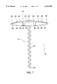
- FIG. 7 is a bottom view of the guide
- FIG. 8 is a top view of the guide
- FIG. 9 is a transverse sectional diagrammatic view showing the upper portion of the guide positioned atop the neck of a bottle.
- FIG. 10 is a front diagrammatic view showing the cork extractor of the present invention positioned atop the neck of a bottle in preparation for extracting a cork;
- FIG. 11 is a front view of the cork extractor positioned atop the neck of a bottle after the cork has been extracted;
- FIG. 12 is an exploded view of the cork extractor showing the corkscrew being inserted into the guide for storage or transport;
- FIG. 13 is a front view of the cork extractor showing the corkscrew completely retained within the guide during storage and transport;
- FIG. 14 is a longitudinal sectional view of the cork extractor of FIG. 13.
- the preferred embodiment of the present invention comprises a self-pulling cork extractor which generally includes two completely separable and individually integral components: a corkscrew 12 as shown in FIG. 1, and a holder or guide 14 as shown in FIG. 5, which cooperate with each other in a manner to be described in more detail hereinbelow.
- corkscrew 12 generally includes a handle 16 from which perpendicularly extends a helical worm 18.
- Worm 18 is conventional and comprises an elongated helical body 44 preferably made of metal which may be coated with a friction-reducing material such as TeflonTM. The friction-reducing coating enables the worm to be driven into a cork more easily, as is well-known.
- Worm 18 also includes a sharpened free end 46 and a distal end which is embedded in handle 16 in a manner to be described below.
- Handle 16 includes a substantially rectangular center portion 20 from both sides of which extend two preferably identical end portions 32. Each end portion 32 is somewhat triangularly shaped, having gently curved sides that taper to a rounded tip 33. Center portion 20 and end portions 32 are preferably made of plastic having a high tensile strength, which may be coated with rubberized paint to provide an easy and attractive surface for the hands of the user to grip.
- Center portion 20 also preferably includes a gently curved top surface 24 which aligns with the top surfaces 34 of end portions 32 when end portions 32 are in the position shown in FIG. 1 (called the "unfolded position"). Center portion 20 further preferably includes a substantially planar lower surface 26 which aligns with the lower surfaces 35 of end portions 32 in the unfolded position.
- center portion 20 preferably includes a pair of oppositely-extending U-shaped yokes 29.
- Each end portion 32 includes an inwardly extending flange 40 which mates with U-shaped yoke 29.
- a pin 42 extends transversely through each of the U-shaped yokes 29 of center portion 20 and flange 40 of end portions 32 so that end portions 32 are enabled to pivot downwardly about pins 42 to the folded position shown in FIG. 4.
- the lower surface 26 of center portion 20 terminates in rounded lower edges 30 which extend the width of center portion 20.
- Rounded lower edges 30 allow end portions 32 to smoothly pivot between their unfolded and folded positions.
- each end portion 32 also preferably includes an oval-shaped nib 36 centrally located on top surface 34.
- the function of nibs 36 will be described in greater detail hereinbelow.
- a clear, rounded protrusion 22 may optionally be centrally located on top surface 24 of center portion 20 for the display, for example, of a trademark and/or company name of the manufacturer.
- FIG. 4 shows end portions 32 in their "folded” or “storage” position.
- end portions 32 When end portions 32 are in their folded position, it exposes two gently arched side surfaces 28 on center portion 20.
- a spring 41 may be provided above flange 40 to assist end portion 32 to remain in its folded and unfolded positions.
- guide 14 is preferably made of plastic having a high tensile strength, and may be coated with rubberized paint to provide an aesthetically pleasing and improved surface for the hands of the user to grip.
- Guide 14 comprises two opposing elongated arms 50 which are joined by a head 52. Arms 50 each generally include an upper portion 54 which extends downwardly from head 52 and a lower portion 56. Positioned approximately at the junction between upper and lower portions 54 and 56 is a substantially planar reaction surface 62, the function of which will be described in greater detail below.
- Arms 50 define open sides 66 therebetween which allow arms 50 to flex both towards and away from each other, thus enabling lower portion 56 to fit over a variety of bottle neck sizes and shapes, as will be described in greater detail below.
- Each upper portion 54 also preferably includes a substantially cylindrical cork receiving surface 64 extending upwardly from reaction surface 62.
- Head 52 includes a substantially planar top surface 57 and a lower surface 55.
- a cylindrical aperture 58 is centrally located in head 52 and extends between top surface 57 and lower surface 55 and is longitudinally oriented with respect to the longitudinal axis of guide 14.
- Aperture 58 receives and guides corkscrew 12 during the extraction of a cork, as will be described below.
- the diameter of aperture 58 is slightly larger than the diameter of worm 18 so as to allow worm 18 to be inserted therethrough while, at the same time, preventing substantial lateral movement of worm 18 during extraction of a cork.
- a pair of inwardly facing, opposing arcuate projections 59 are preferably located on the inside surface of upper portion 54 of each arm 50. Projections 59 cooperate to prevent radial rotation of a cork during extraction thereof, as is conventional.
- Each upper portion 54 also may include a pair of foil cutter tips 60, which operate in conjunction with projections 59 (in a manner to be set forth below) to cut the foil that generally envelopes the neck of a wine bottle.
- Foil cutter tips 60 are generally oriented in a plane which is parallel to the longitudinal axis of guide 14, are preferably made of metal, for durability, and are relatively thin, thereby allowing tips 60 to cut through foil. Tips 60 are preferably rounded and do not have sharpened edges as to avoid cutting a user of the present invention.
- each arm 50 includes a recess 68 having a fairly wide tail 69 at the bottom of arm 50 which gently tapers upwardly to a rounded tip 70.
- Each recess 68 further preferably includes a transverse arcuate ridge 71, a narrow elongated groove 74 which extends upwardly from tail 69, and an aperture 72 which is approximately centrally located in recess 68.
- the process of opening a wine bottle generally involves two steps: (1) removing a foil wrapper from the lip of the bottle to expose the cork, and (2) extracting the cork.
- FIG. 9 illustrates the way in which the present invention facilitates the removal of a foil wrapper.
- FIG. 9 is a cross-sectional view taken along 9--9 of FIG. 5 which shows a bottle 76 positioned in guide 14.
- Bottle 76 has a neck 78 and a lip 80.
- the uppermost portion of neck 78 is enveloped by a foil wrapper 82.
- a cylindrical cork 83 having a diameter approximately equal to the inner diameter of neck 78, is also located within neck 78 and extends upwardly approximately to lip 80.
- guide 14 In order to cut foil wrapper 82, guide 14 is oriented so that its longitudinal axis is perpendicular to the axis of neck 78. Upper portion 54 of guide 14 is lowered upon lip 80 until projections 59 are generally centered over lip 80 and resting thereupon. Arms 50 are gently squeezed towards each other by the user, bringing foil cutter tips 60 closer together until one pair of tips 60 pierce foil wrapper 82. Guide 14 is then manually rotated about neck 78 until a circular cut is made around the perimeter of foil wrapper 82. The top of foil wrapper 82 may then be easily removed, exposing cork 83.
- FIGS. 10 & 11 illustrate how the present invention extracts cork 83 from bottle 76.
- the method to be described is a conventional one for self-pulling corkscrews, and is provided herein for the sake of completeness.
- guide 14 is positioned with its longitudinal axis parallel with the longitudinal axis of bottle 76.
- Worm 18 of corkscrew 12 is inserted through aperture 58 with free end 46 positioned at or above reaction surface 62 (this orientation of corkscrew 12 will be referred to as the "operating orientation").
- Lower portions 56 of guide 14 are lowered around neck 78 of bottle 76 until lip 80 abuts reaction surface 62.
- arms 50 are radially flexible to allow them to be inwardly squeezed so as to prevent rotation of bottle 76 while cork 83 is being extracted.
- it allows guide 14 to expand or contract radially to accommodate a variety of bottle neck sizes and shapes.
- Handle 16 is then rotated and downward pressure is applied thereto, driving free end 46 of worm 18 into cork 83, thereby drawing the corkscrew downwardly into guide 14.
- corkscrew 12 eventually results in lower surface 26 of center portion 20 of handle 16 abutting top To surface 57 of head 52.
- Continued rotation of handle 16 causes cork 83 to be upwardly drawn along body 44 of worm 18 into upper portions 54 of guide 14 without further downward movement of corkscrew 12.
- Handle 16 is preferably rotated until cork 83 is positioned between flanges 59, which prevent radial rotation of cork 83.
- guide 14 can be removed from the neck of bottle 76 and rotation of handle 16 is reversed, withdrawing worm 18 from cork 83.
- corkscrew 12 when it is desired to store or transport the cork extractor, corkscrew 12 can be conveniently stored within guide 14 in a safe, easy and elegant manner.
- FIG. 12 shows how corkscrew 12 is initially inserted into guide 14 for transport or storage, and FIG. 13 shows its final stored position.
- end portions 32 of handle 16 must be folded. Then, as shown in FIG. 12, corkscrew 12 is oriented 180 degrees from its operating orientation, and free end 46 is placed between lower portions 56 of arms 50 and is moved towards head 52.
- each folded end portion 32 of handle 16 fits within a recess 68.
- each groove 74 receives and guides a nib 36 towards an aperture 72.
- Corkscrew 12 is further inserted until each nib 36 is aligned and resting within an aperture 72.
- a portion of each end surface 38 has also been moved beyond and thus rests adjacent one of the arcuate ridges 71, which further serves to hold corkscrew firmly but removably in place within guide 14. It may be said that the end portions 32 have been "snapped" into place within recesses 68.
- aperture 58 is preferably only slightly larger than that of worm 18, thereby preventing free end 46 from injuring the user of the cork extractor during storage or transport.
- corkscrew 12 is preferably retained entirely within guide 14.
- handle 16 it is within the purview of this invention to allow handle 16 to protrude slightly beyond guide 14, as shown in FIG. 14, since handle 16 does not contain any sharp edges or points.
- the present invention may be easily and safely stored in one's pocket, or in a drawer, without fear of being cut when it comes time to use it again.
- the cork extractor of the present invention provides a compact and safe configuration for storage and transport. It is clear from the foregoing that the objects of the invention have been fulfilled.
Abstract
Description
Claims (33)
Priority Applications (4)
| Application Number | Priority Date | Filing Date | Title |
|---|---|---|---|
| US09/227,460 US6151992A (en) | 1999-01-08 | 1999-01-08 | Cork extractor |
| DE10083679T DE10083679T1 (en) | 1999-01-08 | 2000-01-05 | corkscrew |
| GB0115371A GB2361232B (en) | 1999-01-08 | 2000-01-05 | Cork extractor |
| PCT/US2000/000130 WO2000040502A1 (en) | 1999-01-08 | 2000-01-05 | Cork extractor |
Applications Claiming Priority (1)
| Application Number | Priority Date | Filing Date | Title |
|---|---|---|---|
| US09/227,460 US6151992A (en) | 1999-01-08 | 1999-01-08 | Cork extractor |
Publications (1)
| Publication Number | Publication Date |
|---|---|
| US6151992A true US6151992A (en) | 2000-11-28 |
Family
ID=22853203
Family Applications (1)
| Application Number | Title | Priority Date | Filing Date |
|---|---|---|---|
| US09/227,460 Expired - Fee Related US6151992A (en) | 1999-01-08 | 1999-01-08 | Cork extractor |
Country Status (4)
| Country | Link |
|---|---|
| US (1) | US6151992A (en) |
| DE (1) | DE10083679T1 (en) |
| GB (1) | GB2361232B (en) |
| WO (1) | WO2000040502A1 (en) |
Cited By (11)
| Publication number | Priority date | Publication date | Assignee | Title |
|---|---|---|---|---|
| WO2003086948A1 (en) | 2002-04-12 | 2003-10-23 | Heftitec Sa | Cork screw provided with a cap cutter which can be inserted into the handle |
| US6739215B2 (en) | 2001-03-30 | 2004-05-25 | Wki Holding Company, Inc. | Cork extracting device |
| US6823760B1 (en) | 2002-10-31 | 2004-11-30 | Metrokane, Inc. | Cork extractor |
| US20050217434A1 (en) * | 2002-04-23 | 2005-10-06 | Rainer Opolka | Corkscrew |
| US20060225536A1 (en) * | 2005-04-06 | 2006-10-12 | Thomas Hill | Bottle opener for pressurized bottles |
| US20070193415A1 (en) * | 2006-02-23 | 2007-08-23 | Eugene Eric Isaacson | Power driven wine bottle opener |
| US20080098854A1 (en) * | 2006-10-30 | 2008-05-01 | Brookstone Purchasing, Inc. | Bottle opener with integrated wrapper cutter |
| US20110100164A1 (en) * | 2009-10-30 | 2011-05-05 | Wki Holding Company, Inc. | Self-Pulling Corkscrew |
| US8667867B2 (en) | 2011-09-16 | 2014-03-11 | Brookstone Purchasing, Inc. | Powered bottle opening device with integrated wrapper cutter |
| US8915167B2 (en) | 2011-02-10 | 2014-12-23 | Aleksandar Ratajac | Cork screw |
| US9670043B2 (en) | 2014-08-28 | 2017-06-06 | Helen Of Troy Limited | Lever corkscrew with removable wrapper cutter |
Families Citing this family (3)
| Publication number | Priority date | Publication date | Assignee | Title |
|---|---|---|---|---|
| GB2460463B (en) * | 2008-05-30 | 2010-10-20 | Toerags Ltd | Corkscrew |
| EP2681152B1 (en) * | 2011-03-04 | 2014-12-17 | BE Aerospace, Inc. | Mountable cork puller |
| FR3021958B1 (en) | 2014-05-05 | 2017-07-14 | Shalom Ohayon | INTEGRATED CAPPER. |
Citations (16)
| Publication number | Priority date | Publication date | Assignee | Title |
|---|---|---|---|---|
| US171752A (en) * | 1876-01-04 | Improvement in cork-screws | ||
| US613288A (en) * | 1898-11-01 | Anton mazzanovioh | ||
| US814834A (en) * | 1904-12-06 | 1906-03-13 | Benjamin W O Neil | Corkscrew. |
| US1248608A (en) * | 1916-04-08 | 1917-12-04 | Calvin S Brown | Bottle-opener. |
| US2115289A (en) * | 1936-02-17 | 1938-04-26 | Richard G Smythe | Container opener |
| US2886994A (en) * | 1956-08-30 | 1959-05-19 | Alfred H Hanson | Combination bar tool |
| US4276789A (en) * | 1978-07-17 | 1981-07-07 | Hallen Company | Cork extractor |
| US4572034A (en) * | 1984-11-21 | 1986-02-25 | Lee Wen Hsin | Cork screw |
| US4574663A (en) * | 1984-05-02 | 1986-03-11 | Delisle Jr Bernard | Cork extractor |
| US4580303A (en) * | 1984-04-07 | 1986-04-08 | Henshaw Garry E | Bottle opener and resealer |
| US4703673A (en) * | 1985-04-08 | 1987-11-03 | Hallen Company | Cork-extracting apparatus |
| US4750391A (en) * | 1986-04-04 | 1988-06-14 | Stan Dee, Incorporated | Opener for removing champagne-type corks |
| US5351579A (en) * | 1993-05-20 | 1994-10-04 | Robert Metz | Rechargeable electric corkscrew |
| US5361652A (en) * | 1993-02-02 | 1994-11-08 | Diego Andina | Corkscrew |
| US5367923A (en) * | 1990-09-11 | 1994-11-29 | Fabbro; Alberto | Corkscrew that extracts simultaneously with the cork a preventively cut portion of the capsule on the neck of the bottle |
| US5799551A (en) * | 1997-03-18 | 1998-09-01 | Impex Handelsgesellschaft Mbh (F.E.) Ltd. | Corkscrew |
Family Cites Families (2)
| Publication number | Priority date | Publication date | Assignee | Title |
|---|---|---|---|---|
| USD364324S (en) * | 1993-09-27 | 1995-11-21 | Le Creuset S.A. | Table model corkscrew with cutting wheels |
| USD359213S (en) * | 1993-09-27 | 1995-06-13 | Le Creuset, S.A. | Pocket model corkscrew without cutting wheels |
-
1999
- 1999-01-08 US US09/227,460 patent/US6151992A/en not_active Expired - Fee Related
-
2000
- 2000-01-05 WO PCT/US2000/000130 patent/WO2000040502A1/en active Application Filing
- 2000-01-05 DE DE10083679T patent/DE10083679T1/en not_active Ceased
- 2000-01-05 GB GB0115371A patent/GB2361232B/en not_active Expired - Fee Related
Patent Citations (17)
| Publication number | Priority date | Publication date | Assignee | Title |
|---|---|---|---|---|
| US171752A (en) * | 1876-01-04 | Improvement in cork-screws | ||
| US613288A (en) * | 1898-11-01 | Anton mazzanovioh | ||
| US814834A (en) * | 1904-12-06 | 1906-03-13 | Benjamin W O Neil | Corkscrew. |
| US1248608A (en) * | 1916-04-08 | 1917-12-04 | Calvin S Brown | Bottle-opener. |
| US2115289A (en) * | 1936-02-17 | 1938-04-26 | Richard G Smythe | Container opener |
| US2886994A (en) * | 1956-08-30 | 1959-05-19 | Alfred H Hanson | Combination bar tool |
| US4276789B1 (en) * | 1978-07-17 | 1991-10-29 | Hallen Co | |
| US4276789A (en) * | 1978-07-17 | 1981-07-07 | Hallen Company | Cork extractor |
| US4580303A (en) * | 1984-04-07 | 1986-04-08 | Henshaw Garry E | Bottle opener and resealer |
| US4574663A (en) * | 1984-05-02 | 1986-03-11 | Delisle Jr Bernard | Cork extractor |
| US4572034A (en) * | 1984-11-21 | 1986-02-25 | Lee Wen Hsin | Cork screw |
| US4703673A (en) * | 1985-04-08 | 1987-11-03 | Hallen Company | Cork-extracting apparatus |
| US4750391A (en) * | 1986-04-04 | 1988-06-14 | Stan Dee, Incorporated | Opener for removing champagne-type corks |
| US5367923A (en) * | 1990-09-11 | 1994-11-29 | Fabbro; Alberto | Corkscrew that extracts simultaneously with the cork a preventively cut portion of the capsule on the neck of the bottle |
| US5361652A (en) * | 1993-02-02 | 1994-11-08 | Diego Andina | Corkscrew |
| US5351579A (en) * | 1993-05-20 | 1994-10-04 | Robert Metz | Rechargeable electric corkscrew |
| US5799551A (en) * | 1997-03-18 | 1998-09-01 | Impex Handelsgesellschaft Mbh (F.E.) Ltd. | Corkscrew |
Cited By (14)
| Publication number | Priority date | Publication date | Assignee | Title |
|---|---|---|---|---|
| US6739215B2 (en) | 2001-03-30 | 2004-05-25 | Wki Holding Company, Inc. | Cork extracting device |
| WO2003086948A1 (en) | 2002-04-12 | 2003-10-23 | Heftitec Sa | Cork screw provided with a cap cutter which can be inserted into the handle |
| US20050050643A1 (en) * | 2002-04-12 | 2005-03-10 | Heftitec Sa | Cork screw provided with a cap cutter which can be inserted in the handle |
| US7024715B2 (en) * | 2002-04-12 | 2006-04-11 | Heftitec Sa | Cork screw provided with a cap cutter which can be inserted in the handle |
| US20050217434A1 (en) * | 2002-04-23 | 2005-10-06 | Rainer Opolka | Corkscrew |
| US6823760B1 (en) | 2002-10-31 | 2004-11-30 | Metrokane, Inc. | Cork extractor |
| US20060225536A1 (en) * | 2005-04-06 | 2006-10-12 | Thomas Hill | Bottle opener for pressurized bottles |
| US20070193415A1 (en) * | 2006-02-23 | 2007-08-23 | Eugene Eric Isaacson | Power driven wine bottle opener |
| US20080098854A1 (en) * | 2006-10-30 | 2008-05-01 | Brookstone Purchasing, Inc. | Bottle opener with integrated wrapper cutter |
| US7481134B2 (en) | 2006-10-30 | 2009-01-27 | Brookstone Purchasing, Inc. | Bottle opener with integrated wrapper cutter |
| US20110100164A1 (en) * | 2009-10-30 | 2011-05-05 | Wki Holding Company, Inc. | Self-Pulling Corkscrew |
| US8915167B2 (en) | 2011-02-10 | 2014-12-23 | Aleksandar Ratajac | Cork screw |
| US8667867B2 (en) | 2011-09-16 | 2014-03-11 | Brookstone Purchasing, Inc. | Powered bottle opening device with integrated wrapper cutter |
| US9670043B2 (en) | 2014-08-28 | 2017-06-06 | Helen Of Troy Limited | Lever corkscrew with removable wrapper cutter |
Also Published As
| Publication number | Publication date |
|---|---|
| GB2361232A (en) | 2001-10-17 |
| GB2361232B (en) | 2003-01-15 |
| GB0115371D0 (en) | 2001-08-15 |
| DE10083679T1 (en) | 2002-01-31 |
| WO2000040502A1 (en) | 2000-07-13 |
Similar Documents
| Publication | Publication Date | Title |
|---|---|---|
| US6151992A (en) | Cork extractor | |
| US4706668A (en) | Aneurysm clip pliers | |
| JP2580018B2 (en) | Trocar assembly | |
| US6203418B1 (en) | Precision taxidermy and field-use micro cutting system | |
| US4750491A (en) | Trephine and method | |
| KR860002067B1 (en) | Cork extractor | |
| US5896667A (en) | Plastic wrap piercing-cutting device | |
| US4525928A (en) | Blade opening scabbard for folding knife | |
| US4637139A (en) | Ampoule cutter | |
| US6173497B1 (en) | Nail clippers | |
| US6752040B1 (en) | Container opener | |
| US20090107347A1 (en) | Egg breaker | |
| JP2004526640A (en) | Corkscrew | |
| US5010648A (en) | Gray hair cutter | |
| US5095777A (en) | Can opening device | |
| US5437679A (en) | Nail splitter device for implementing a wedge resection procedure to remove an ingrown toenail | |
| US4291464A (en) | Lid piercing device | |
| US20050050643A1 (en) | Cork screw provided with a cap cutter which can be inserted in the handle | |
| US6161550A (en) | Cigar holder with cutter | |
| US20040102800A1 (en) | Trimmer for cutting a coiled strand | |
| US5060387A (en) | Blade handle | |
| US5010790A (en) | Apparatus for removing a soft stopper from a container | |
| US4395823A (en) | Shell fish opener | |
| US4916985A (en) | Apparatus for removing a soft stopper from a container | |
| US20210395064A1 (en) | Lateral-cutting can opener assembly |
Legal Events
| Date | Code | Title | Description |
|---|---|---|---|
| AS | Assignment |
Owner name: METROKANE, INC., NEW YORK Free format text: ASSIGNMENT OF ASSIGNORS INTEREST;ASSIGNOR:LARIMER, ROBERT W.;REEL/FRAME:009707/0647 Effective date: 19990107 |
|
| AS | Assignment |
Owner name: METROKANE, INC., NEW YORK Free format text: ASSIGNMENT OF ASSIGNORS INTEREST;ASSIGNOR:KILDUFF, EDWARD;REEL/FRAME:011253/0254 Effective date: 20001010 |
|
| CC | Certificate of correction | ||
| REMI | Maintenance fee reminder mailed | ||
| REIN | Reinstatement after maintenance fee payment confirmed | ||
| FP | Lapsed due to failure to pay maintenance fee |
Effective date: 20041128 |
|
| FEPP | Fee payment procedure |
Free format text: PETITION RELATED TO MAINTENANCE FEES GRANTED (ORIGINAL EVENT CODE: PMFG); ENTITY STATUS OF PATENT OWNER: SMALL ENTITY |
|
| FEPP | Fee payment procedure |
Free format text: PETITION RELATED TO MAINTENANCE FEES FILED (ORIGINAL EVENT CODE: PMFP); ENTITY STATUS OF PATENT OWNER: SMALL ENTITY |
|
| FPAY | Fee payment |
Year of fee payment: 4 |
|
| SULP | Surcharge for late payment | ||
| PRDP | Patent reinstated due to the acceptance of a late maintenance fee |
Effective date: 20061006 |
|
| REMI | Maintenance fee reminder mailed | ||
| LAPS | Lapse for failure to pay maintenance fees | ||
| STCH | Information on status: patent discontinuation |
Free format text: PATENT EXPIRED DUE TO NONPAYMENT OF MAINTENANCE FEES UNDER 37 CFR 1.362 |
|
| FP | Lapsed due to failure to pay maintenance fee |
Effective date: 20081128 |
|
| AS | Assignment |
Owner name: TAYLOR PRECISION PRODUCTS, INC., ILLINOIS Free format text: ASSIGNMENT OF ASSIGNORS INTEREST;ASSIGNOR:METROKANE, INC.;REEL/FRAME:031586/0703 Effective date: 20131112 |
|
| AS | Assignment |
Owner name: GENERAL ELECTRIC CAPITAL CORPORATION, AS AGENT, CO Free format text: SECURITY AGREEMENT;ASSIGNOR:TAYLOR PRECISION PRODUCTS, INC.;REEL/FRAME:031644/0233 Effective date: 20131112 |
|
| AS | Assignment |
Owner name: TAYLOR PRECISION PRODUCTS, INC., WASHINGTON Free format text: RELEASE OF SECURITY INTEREST RECORDED AT REEL/FRAME 028417/0058 AND 031644/0233;ASSIGNOR:ANTARES CAPITAL LP, AS SUCCESSOR TO GENERAL ELECTRIC CAPITAL CORPORATION, AS AGENT;REEL/FRAME:045726/0886 Effective date: 20180302 |