US6150731A - Integrated high frequency marine power distribution arrangement with transformerless high voltage variable speed drive - Google Patents
Integrated high frequency marine power distribution arrangement with transformerless high voltage variable speed drive Download PDFInfo
- Publication number
- US6150731A US6150731A US09/250,758 US25075899A US6150731A US 6150731 A US6150731 A US 6150731A US 25075899 A US25075899 A US 25075899A US 6150731 A US6150731 A US 6150731A
- Authority
- US
- United States
- Prior art keywords
- power
- generator
- frequency
- phase
- isolated
- Prior art date
- Legal status (The legal status is an assumption and is not a legal conclusion. Google has not performed a legal analysis and makes no representation as to the accuracy of the status listed.)
- Expired - Fee Related
Links
- 238000002955 isolation Methods 0.000 claims description 3
- 238000006243 chemical reaction Methods 0.000 abstract description 13
- 238000001816 cooling Methods 0.000 description 6
- 238000004804 winding Methods 0.000 description 4
- 238000003491 array Methods 0.000 description 3
- 239000004065 semiconductor Substances 0.000 description 3
- 238000010586 diagram Methods 0.000 description 2
- 238000000034 method Methods 0.000 description 2
- 238000012986 modification Methods 0.000 description 2
- 230000004048 modification Effects 0.000 description 2
- 239000007787 solid Substances 0.000 description 2
- 230000001419 dependent effect Effects 0.000 description 1
- 230000016507 interphase Effects 0.000 description 1
- 239000007788 liquid Substances 0.000 description 1
- 230000007935 neutral effect Effects 0.000 description 1
- 238000010248 power generation Methods 0.000 description 1
- XLYOFNOQVPJJNP-UHFFFAOYSA-N water Substances O XLYOFNOQVPJJNP-UHFFFAOYSA-N 0.000 description 1
Images

Classifications
-
- H—ELECTRICITY
- H02—GENERATION; CONVERSION OR DISTRIBUTION OF ELECTRIC POWER
- H02M—APPARATUS FOR CONVERSION BETWEEN AC AND AC, BETWEEN AC AND DC, OR BETWEEN DC AND DC, AND FOR USE WITH MAINS OR SIMILAR POWER SUPPLY SYSTEMS; CONVERSION OF DC OR AC INPUT POWER INTO SURGE OUTPUT POWER; CONTROL OR REGULATION THEREOF
- H02M7/00—Conversion of AC power input into DC power output; Conversion of DC power input into AC power output
- H02M7/42—Conversion of DC power input into AC power output without possibility of reversal
- H02M7/44—Conversion of DC power input into AC power output without possibility of reversal by static converters
- H02M7/48—Conversion of DC power input into AC power output without possibility of reversal by static converters using discharge tubes with control electrode or semiconductor devices with control electrode
- H02M7/483—Converters with outputs that each can have more than two voltages levels
- H02M7/49—Combination of the output voltage waveforms of a plurality of converters
-
- B—PERFORMING OPERATIONS; TRANSPORTING
- B63—SHIPS OR OTHER WATERBORNE VESSELS; RELATED EQUIPMENT
- B63H—MARINE PROPULSION OR STEERING
- B63H21/00—Use of propulsion power plant or units on vessels
- B63H21/12—Use of propulsion power plant or units on vessels the vessels being motor-driven
- B63H21/17—Use of propulsion power plant or units on vessels the vessels being motor-driven by electric motor
-
- B—PERFORMING OPERATIONS; TRANSPORTING
- B63—SHIPS OR OTHER WATERBORNE VESSELS; RELATED EQUIPMENT
- B63H—MARINE PROPULSION OR STEERING
- B63H23/00—Transmitting power from propulsion power plant to propulsive elements
- B63H23/22—Transmitting power from propulsion power plant to propulsive elements with non-mechanical gearing
- B63H23/24—Transmitting power from propulsion power plant to propulsive elements with non-mechanical gearing electric
-
- B—PERFORMING OPERATIONS; TRANSPORTING
- B63—SHIPS OR OTHER WATERBORNE VESSELS; RELATED EQUIPMENT
- B63J—AUXILIARIES ON VESSELS
- B63J3/00—Driving of auxiliaries
- B63J3/02—Driving of auxiliaries from propulsion power plant
-
- H—ELECTRICITY
- H02—GENERATION; CONVERSION OR DISTRIBUTION OF ELECTRIC POWER
- H02M—APPARATUS FOR CONVERSION BETWEEN AC AND AC, BETWEEN AC AND DC, OR BETWEEN DC AND DC, AND FOR USE WITH MAINS OR SIMILAR POWER SUPPLY SYSTEMS; CONVERSION OF DC OR AC INPUT POWER INTO SURGE OUTPUT POWER; CONTROL OR REGULATION THEREOF
- H02M5/00—Conversion of AC power input into AC power output, e.g. for change of voltage, for change of frequency, for change of number of phases
- H02M5/40—Conversion of AC power input into AC power output, e.g. for change of voltage, for change of frequency, for change of number of phases with intermediate conversion into DC
- H02M5/42—Conversion of AC power input into AC power output, e.g. for change of voltage, for change of frequency, for change of number of phases with intermediate conversion into DC by static converters
- H02M5/44—Conversion of AC power input into AC power output, e.g. for change of voltage, for change of frequency, for change of number of phases with intermediate conversion into DC by static converters using discharge tubes or semiconductor devices to convert the intermediate DC into AC
- H02M5/453—Conversion of AC power input into AC power output, e.g. for change of voltage, for change of frequency, for change of number of phases with intermediate conversion into DC by static converters using discharge tubes or semiconductor devices to convert the intermediate DC into AC using devices of a triode or transistor type requiring continuous application of a control signal
- H02M5/458—Conversion of AC power input into AC power output, e.g. for change of voltage, for change of frequency, for change of number of phases with intermediate conversion into DC by static converters using discharge tubes or semiconductor devices to convert the intermediate DC into AC using devices of a triode or transistor type requiring continuous application of a control signal using semiconductor devices only
-
- H—ELECTRICITY
- H02—GENERATION; CONVERSION OR DISTRIBUTION OF ELECTRIC POWER
- H02M—APPARATUS FOR CONVERSION BETWEEN AC AND AC, BETWEEN AC AND DC, OR BETWEEN DC AND DC, AND FOR USE WITH MAINS OR SIMILAR POWER SUPPLY SYSTEMS; CONVERSION OF DC OR AC INPUT POWER INTO SURGE OUTPUT POWER; CONTROL OR REGULATION THEREOF
- H02M7/00—Conversion of AC power input into DC power output; Conversion of DC power input into AC power output
- H02M7/42—Conversion of DC power input into AC power output without possibility of reversal
- H02M7/44—Conversion of DC power input into AC power output without possibility of reversal by static converters
- H02M7/48—Conversion of DC power input into AC power output without possibility of reversal by static converters using discharge tubes with control electrode or semiconductor devices with control electrode
- H02M7/483—Converters with outputs that each can have more than two voltages levels
- H02M7/4835—Converters with outputs that each can have more than two voltages levels comprising two or more cells, each including a switchable capacitor, the capacitors having a nominal charge voltage which corresponds to a given fraction of the input voltage, and the capacitors being selectively connected in series to determine the instantaneous output voltage
-
- B—PERFORMING OPERATIONS; TRANSPORTING
- B60—VEHICLES IN GENERAL
- B60L—PROPULSION OF ELECTRICALLY-PROPELLED VEHICLES; SUPPLYING ELECTRIC POWER FOR AUXILIARY EQUIPMENT OF ELECTRICALLY-PROPELLED VEHICLES; ELECTRODYNAMIC BRAKE SYSTEMS FOR VEHICLES IN GENERAL; MAGNETIC SUSPENSION OR LEVITATION FOR VEHICLES; MONITORING OPERATING VARIABLES OF ELECTRICALLY-PROPELLED VEHICLES; ELECTRIC SAFETY DEVICES FOR ELECTRICALLY-PROPELLED VEHICLES
- B60L2200/00—Type of vehicles
- B60L2200/32—Waterborne vessels
-
- Y—GENERAL TAGGING OF NEW TECHNOLOGICAL DEVELOPMENTS; GENERAL TAGGING OF CROSS-SECTIONAL TECHNOLOGIES SPANNING OVER SEVERAL SECTIONS OF THE IPC; TECHNICAL SUBJECTS COVERED BY FORMER USPC CROSS-REFERENCE ART COLLECTIONS [XRACs] AND DIGESTS
- Y02—TECHNOLOGIES OR APPLICATIONS FOR MITIGATION OR ADAPTATION AGAINST CLIMATE CHANGE
- Y02T—CLIMATE CHANGE MITIGATION TECHNOLOGIES RELATED TO TRANSPORTATION
- Y02T70/00—Maritime or waterways transport
- Y02T70/50—Measures to reduce greenhouse gas emissions related to the propulsion system
Definitions
- Transformer power density i.e. size or weight per unit power
- the main variables which will influence size and weight are: (1) specified sound level requirements (both airborne and structureborne); (2) operating electrical frequency; (3) operating voltage; (4) voltage impulse and dielectric levels; (5) phase shifting requirements; (6) efficiency; (7) type and configuration of cooling system (air, water, forced); and (8) winding configurations, e.g. arrangement of multiple windings.
- the generator 14 is configured as a multi-phase, multi-circuit machine.
- the generator may be configured with any number of circuits and phases dependent on power module topologies and configurations.
- Table 3 illustrates examples of possible medium voltage PWM motor drive configurations based on a typical 315 kW power module. Other configurations are also possible.
Landscapes
- Engineering & Computer Science (AREA)
- Power Engineering (AREA)
- Chemical & Material Sciences (AREA)
- Combustion & Propulsion (AREA)
- Mechanical Engineering (AREA)
- Ocean & Marine Engineering (AREA)
- Control Of Eletrric Generators (AREA)
- Supply And Distribution Of Alternating Current (AREA)
Abstract
A marine power distribution arrangement utilizes generators driven at standard or higher than normal speeds and/or having a number of poles to produce electric power at a standard 50/60 Hz frequency or substantially higher than the standard 50/60 Hz frequency, such as 400 Hz. Each generator is a multi-phase, multi-circuit generator supplying isolated outputs on a plurality of lines to a propulsion power converter having isolated inputs to provide variable frequency, variable voltage power to a ship propulsion motor and to a service power converter to provide ship service power at a standard AC frequency or DC and at standard voltage for a service load. With this arrangement, power conversion transformers can, for the most part, be eliminated, thereby reducing the size and weight of the distribution system.
Description
This invention relates to marine power distribution systems for supplying drive power of variable frequency and variable voltage for a ship propulsion motor as well as fixed frequency standard voltage power for ship service loads.
Conventional integrated marine electric drive systems generate AC power at 60 Hz and either utilize the AC power directly at 60 Hz, through frequency converters for ship's propulsion motors and transformers for ship's auxiliary power circuits, or rectify the AC power from the generator and distribute direct current (DC) power and then convert the DC power to AC power using conversion equipment for the ship's propulsion motors and also for the ship's auxiliary loads.
The commercial industry as well as the military has many years of experience generating and distributing power at 50/60 Hz. Conventional 50/60 Hz generators operate at speeds of 1200 rpm up to 3600 rpm. This is shown below and in Table 1.
Frequency: ##EQU1##
              TABLE 1
______________________________________
Limitation of 50/60 Hz Generators
rpm           Number of Poles
                          Frequency
______________________________________
3600/3000     2           60/50
1800/1500     4           60/50
1200/1000     6           60/50
______________________________________
The size and weight of a generator are inversely related to the generator speed and the generator pole number in the following manner; Size∝1/(rpm·poles) and Weight∝1/(rpm·poles). Consequently, Size and Weight∝1/(rpm·poles). Therefore, to provide a higher power density, resulting in a reduction of size and weight for a given power level, a higher generator frequency (>60 Hz) must be provided by using a higher generator speed (>3600 rpm) and/or a higher pole number (>2).
The use of a higher frequency to increase power density has been employed successfully by 400 Hz distribution systems in the aircraft industry. However, no such application has been shown to be feasible in conjunction with 60 Hz (or other AC or DC power) for both service power and vehicle propulsion in marine vessels. Since higher power density is important for marine applications, a generator for such applications should produce high frequency power as a result of either an increased generator speed, a higher pole number (>2) or a combination of both.
Transformer power density, i.e. size or weight per unit power, is affected by many variables. The main variables which will influence size and weight are: (1) specified sound level requirements (both airborne and structureborne); (2) operating electrical frequency; (3) operating voltage; (4) voltage impulse and dielectric levels; (5) phase shifting requirements; (6) efficiency; (7) type and configuration of cooling system (air, water, forced); and (8) winding configurations, e.g. arrangement of multiple windings. As the required power levels increase the motor drive input transformer weights make up a larger percentage of the overall system weight. Studies have shown that transformers have an average power density of 3.5 lbs/hp for large-scale motor power conversion equipment. However, depending on system requirements, the transformer power density has been estimated in the range of 2.3 lbs/hp to 5.6 lbs/hp. Normally, to achieve the best power densities in the range of 2 lbs/hp, higher operating frequencies and forced cooling of some type must be used. When supplying ships with shaft horsepower from 25,000 shp to 100,000 shp or higher the transformer weight becomes significant. Table 2 provides an indication of transformer weights at various shaft horsepower levels and power densities.
              TABLE 2
______________________________________
Transformer Weight versus Shaft Horsepower
            Transformer  Transformer
Shaft       Weight (lbs) Weight (lbs)
Horsepower  (Power Density 2.3
                         (Power Density 5.6
Level       lbs/hp)      lbs/hp)
______________________________________
25,000      57,500       140,000
50,000      115,000      280,000
80,000      184,000      448,000
100,000     230,000      560,000
______________________________________
In the Satterthwaite et al. U.S. Pat. No. 4,661,714, an electric marine propulsion system includes two diesel engines connected to drive corresponding alternators at a speed which is two or three times the normal operating speed of the alternators, thereby producing power at a frequency two or three times the standard 60 Hz frequency, i.e. from 120 Hz to up to 180 Hz. The generator outputs are supplied through a ship service switchboard to a series of frequency converters which supply ship propulsion motors with power at frequencies which may vary from 0 to 60 Hz. In addition, the switchboard supplies high frequency power to a transformer and frequency converter for the ship's service utility and auxiliary power at standard 60 Hz frequency.
The Levedahl et al. U.S. Pat. No. 5,684,690 discloses an electric power supply system for propulsion and service control in which each engine turbine drives both a service alternator and a separate propulsion alternator.
The patent to Limpaecher, U.S. Pat. No. 5,270,913, relates to a transformerless semiconductor power conversion system in which a series of H-bridges are used to convert AC power to high voltage DC power. Similarly, the Bansal et al. U.S. Pat. No. 4,780,569 uses H-bridge rectifiers receiving power from a plurality of AC generators with phase-shifted output windings supplying AC power to isolated H-bridge rectifier arrangements to produce a high voltage DC output, while the patent to O'Brien, Jr., U.S. Pat. No. 4,114,555, discloses a power supply for a marine vessel in which a plurality of diesel motor-AC generator units are connected in parallel to provide AC power that is rectified and voltage-controlled by a plurality of SCRs supplying DC motors, thereby avoiding the use of transformers in a propulsion motor power supply.
In integrated electric plants of the prior art, limitations of frequency, voltage, and generator arrangement are presented. Such limited integrated electric power distribution systems have certain disadvantages with respect to power density, i.e. size and weight.
Accordingly, it is an object of the present invention to provide an integrated high frequency marine power distribution arrangement with a transformerless high voltage variable speed drive which overcomes disadvantages of the prior art.
Another object of the invention is to provide an integrated standard (60 Hz) or higher (>60 Hz) frequency marine power distribution arrangement having reduced space and weight requirements.
These and other objects of the invention are attained by providing a marine power distribution system containing a multi-phase, multi-circuit power generator which supplies power through a plurality of isolated output circuits to two arrays of modular multi-level, multi-phase, multi-circuit power conversion units for supplying propulsion power at a variable frequency and voltage, and service load power at a standard frequency and voltage including DC voltage.
Further objects and advantages of the invention will be apparent from a reading of the following description in conjunction with the accompanying drawings, in which:
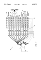
FIG. 1 is a schematic block diagram illustrating a representative embodiment of an integrated high frequency marine power distribution system in accordance with the invention providing power to a propulsion motor and to service loads from a single turbine and high frequency generator; and
FIG. 2 is a schematic block diagram illustrating another embodiment of the invention having two separate electric plants with two turbines each driving corresponding high frequency generators to supply power to two propulsion motors as well as to ship service loads.
Conventional marine propulsion motor power converters must be able to provide variable voltage and variable frequency power to a ship propulsion motor to control the motor speed. However, service loads for a ship typically require power at a fixed voltage and frequency, usually 120 volts AC or 480 volts AC at 50/60 Hz. Where power is generated at a frequency above 60 Hz such as 400 Hz, the service power converter must convert the high frequency input power to the required fixed frequency power and the propulsion motor power converter must convert the high frequency input power to a variable voltage and variable frequency power.
Isolated AC input power sources for such converters are normally derived from one or more transformers. The size and weight of a motor drive input transformer for such applications is substantial and can amount to 50% or more of the total motor drive size and weight. As an example, a small size marine propulsion motor in the range of 25,000 shaft horsepower receives power from two motor drives and power conversion equipment rated for approximately 10 MW each. As shown in Table 2 above, the necessary transformers for this drive can weigh as much as 140,000 pounds total. Techniques such as transformer liquid cooling, modular transformer configurations and higher frequency distribution can reduce transformer size and weight but transformer weight is still a significant portion of the total motor drive weight. Motor drive size and weight are important aspects for marine applications because of the necessary limitations in size and arrangement of the components.
A preferred embodiment of the invention includes a multi-phase, multi-circuit generator, and two arrays of multi-level, multi-phase, multi-circuit power conversion equipment. The power conversion equipment arrays receive power from isolated 3-phase electrical input sources of either standard (60 Hz) or non-standard (>60 Hz) power system frequencies, and may be configured in parallel and in series configurations to increase the output power and voltage levels in addition to providing multi-phase outputs. One array provides power to the propulsion motor and the other provides power to the ship service loads.
Input electrical isolation for the power conversion modules is provided by the generator itself. For example, for a particular 10 MW (12,000 HP) motor drive configuration requiring thirty isolated three-phase power supplies, instead of using a specialized phase shifting, multi-pulse, transformer with multiple secondaries, thirty 3-phase circuits which are taken directly from the generator can accomplish the necessary isolation of the drive power module inputs. The thirty 3-phase sets (90 wires) can be derived from 6, 9, 12, 15, 18 etc., generator phases, depending on the required system power quality requirements. The number of circuits will also increase with the requirement to supply ship service power conversion equipment.
Because solid state power conversion requires rectification (the above-referenced power module loads are 3-phase, 6-pulse rectifiers) power quality, i.e. the presence of harmonics, becomes an issue. If a 30 pulse system were required to reduce harmonic content caused by the individual 6-pulse 3-phase power module rectification process, a 15 phase generator would be necessary. The output of the generator in this case would provide 6 outputs from each 3-phase group. Therefore, the number of isolated 3-phase circuits required at the generator output terminals (`circuits in hand`) is based on the number of motor drive power modules and the phase number is based on system requirements regarding harmonics, i.e. power quality, given that the power module loads are 3-phase, 6-pulse, rectifiers.
Complexity is added to the generator arrangement for an increased phase number and to directly wire out multiple isolated circuits to the generator connection enclosure. For example, a 16 MW, 15 phase, low voltage (600 vac) multi-circuit generator would require approximately 60% more volume in the generator than a similar 16 MW, 3 phase medium voltage (13.8 kV) generator in order to make the large number of necessary connections. Studies on multi-phase generators have indicated that the weight of the multi-phase machines does not increase significantly. However, a 10 MW propulsion motor drive input transformer could weigh a minimum of 27,500 lbs when operated at higher distribution frequencies and provided with innovative cooling designs. Using the standard cooling methods, i.e. air cooling, and distribution frequencies (60 Hz) can easily double the transformer weight, i.e. to approximately 55,000 lbs.
In the typical integrated marine power distribution arrangement 10 shown in FIG. 1, a turbine 12 drives a standard or high frequency >60 Hz generator 14 arranged to provide output power on thirty electrically isolated 3-phase circuits 16, each of which has a relatively low voltage, for example 600 VAC, and each of which is electrically isolated from the others. The 3-phase circuits 16 from the generator are connected to corresponding power modules 1A-5F in a motor drive power converter 22 through electrical protection devices (fuses or circuit breakers) mounted in switchgear 18 and isolated 3-phase cable groups 20. In this example the motor drive power converter 22 is configured to provide a 4,160 volt, medium voltage output for the motor drive. Other configurations of motor drive power modules can be provided.
In the illustrated arrangement 10, three further separate circuits 24 are provided from each phase group to supply power modules 1SA-5SC in a ship service power converter 26. Supplying power to ship service from each phase group effectively balances the generator loading among the phases. The ship service power converter output is variable in voltage, frequency and power as required to supply ship service loads. One or more of various ship service distribution voltages, e.g. 4,160 VAC, 450 VAC, and DC are supplied depending on platform requirements. An input transformer 34 or output transformer 36 may be included if required for the ship service power converter depending on final ship service load needs. Since ship service electrical loads are normally only a small percentage, approximately 10% or less, of the total ship power generation, overall system power density will not be impacted significantly by the use of such transformers.
Each of the power converters 22 and 26 may be of the type disclosed in the copending application of Duba et al. Ser. No. 09/046,076, filed Mar. 23, 1998, the disclosure of which is incorporated herein by reference, to which isolated AC input power is required for each of the inputs. Additionally, the topology or electrical configuration of the motor drive power modules allows many configurations of generator phase and circuit numbers to be derived. Although the embodiments are described herein in terms of specific phase and circuit numbers the invention may be applied to other multi-circuit, multi-phase transformerless power conversion configurations, as well.
To provide the required number of isolated inputs to a modular multi-circuit power converter, the generator 14 is configured as a multi-phase, multi-circuit machine. Alternatively, the generator may be configured with any number of circuits and phases dependent on power module topologies and configurations. Table 3 illustrates examples of possible medium voltage PWM motor drive configurations based on a typical 315 kW power module. Other configurations are also possible.
              TABLE 3
______________________________________
Generator/Drive Phase Circuit Configuration
        5 Level,  4 Level,   3 Level,
                                     5 Level,
        4,160 VAC,
                  3,300 VAC, 2,400 VAC,
                                     4,160 VAC,
        12,500 HP,
                  10,000 HP, 7,600 HP,
                                     25,000 HP,
        6-Phase   6-Phase    6-Phase 6-Phase
        Drive     Drive      Drive   Drive
Generator
        Circuits per
                  Circuits per
                             Circuits per
                                     Circuits per
Phases  Phase     Phase      Phase   Phase
______________________________________
9       --        --         6       --
12      --        6          --      --
15      6         --         --      6
______________________________________
It should be noted that the drive topology allows interphase transformer connection at the midpoint nodes of two pairs of semiconductors in each power module H-bridge, i.e., parallel module operation, effectively doubling the power level of an isolated circuit.
The phases and circuits of the generator 14 must be insulated from each other (phase to phase, phase to circuit, and circuit to circuit) for up to twice the drive output voltage (line to neutral) plus 1,000 volts. The number of circuits in the generator 14 is preferably a multiple of three to balance the magnetic fields in the generator.
The generator output voltage of each 3-phase set should be a relatively low voltage (˜600 VAC) for compatibility with the power converters 22 and 26 which utilize commercially available semiconductors having a withstand voltage in the range of 1,200 to 1,700 volts.
FIG. 2 is a schematic illustration of a typical marine application of the invention utilizing two electric plants 40 and 42 for driving corresponding propulsion motors 44 and 46, respectively, each of the propulsion motors being supplied with power from two power supply arrangements of the type described above with reference to FIG. 1. Thus, the propulsion motor 44 is connected to receive power from two power supply arrangements 48 and 50 and the propulsion motor 46 is connected to receive power from two power supply arrangements 52 and 54.
Inasmuch as the high frequency generators 14 produce a relatively low voltage output of approximately 600 volts AC with correspondingly high currents, system protection is necessary in addition to the isolated generator feeds to the motor drive circuits. However, the multi-phase, multi-circuit generator has the advantage of limiting fault currents because of the many isolated circuit windings. For example, a propulsion generator rated 12 MW at 600 VAC (0.9 pf) with five phase groups and six isolated three-phase circuits per phase group will have a full load current in one feed circuit of 428 amps continuous and 2,850 amps of available symmetrical fault currents if a subtransient reactance of 15% is assumed. Any of several circuit interruption options may be used for protection in such circuits, such as fuses, air (AQB) circuit breakers, solid state interrupters, and controllable SCR-based rectifiers in the generator output circuits to provide a DC distribution system. Circuit protection in the latter arrangement would require removal of the rectifiers in each motor drive power module and this would also require that the generator maintain symmetrical power delivery over all operating profiles and it would be necessary to avoid imposing electrical imbalances in the generator as a result of motor drive faults.
If desired, service voltages and frequencies other than the standard service voltage range of 120 to 480 volts AC and 50/60 Hz can be provided and DC service loads can be accommodated using only a transformer (if necessary) and rectifier stage. In addition, power supplies of the type described herein can be utilized as separate point-of-need power supplies, each located in close proximity to a particular load requiring its use, thereby eliminating voltage drop problems on platforms with loads that require high frequency power. Moreover, backup DC power can be provided in the event of a failure of the main power generator, for example, by onboard batteries connected directly to the power conversion modules.
Although the invention has been described herein with reference to specific embodiments, many modifications and variations therein will readily occur to those skilled in the art. Accordingly, all such variations and modifications are included within the intended scope of the invention.
Claims (5)
1. A marine power distribution arrangement comprising:
a generator for generating a plurality of standard (50/60 Hz) to higher (>60 Hz) frequency AC phases at a plurality of isolated low voltage outputs;
a motive power source for driving the generator;
a plurality of electrical lines, each transmitting power from one of the plurality of isolated low voltage outputs of the generator;
a propulsion power converter connected to receive power directly from the isolated low voltage outputs of the generator and to provide a variable voltage, variable frequency output having a voltage higher than that of the low voltage outputs; and,
a marine propulsion motor connected to receive the variable voltage, variable frequency output from the power converter.
2. A marine power distribution arrangement according to claim 1 including a ship service power converter receiving power from the plurality of isolated generator outputs and providing ship service power at a selected voltage and frequency.
3. A marine power distribution arrangement according to claim 2 including switchgear for connecting the isolated generator outputs to both the propulsion power converter and the ship service power converter.
4. A marine power distribution arrangement according to claim 3 wherein the switchgear includes protection circuits.
5. A marine power distribution arrangement according to claim 3 including an isolation transformer electrically connected between the ship service power converter and the isolated generator outputs.
Priority Applications (4)
| Application Number | Priority Date | Filing Date | Title |
|---|---|---|---|
| US09/250,758 US6150731A (en) | 1999-02-16 | 1999-02-16 | Integrated high frequency marine power distribution arrangement with transformerless high voltage variable speed drive |
| EP00200219A EP1029783A3 (en) | 1999-02-16 | 2000-01-20 | Marine power distribution arrangement |
| JP2000038523A JP2000233798A (en) | 1999-02-16 | 2000-02-16 | Integrated high frequency power distributor used inboard which has transformer-free high voltage variable speed driving device |
| US09/539,426 US6175163B1 (en) | 1999-02-16 | 2000-03-30 | Integrated high frequency marine power distribution arrangement with transformerless high voltage variable speed drive |
Applications Claiming Priority (1)
| Application Number | Priority Date | Filing Date | Title |
|---|---|---|---|
| US09/250,758 US6150731A (en) | 1999-02-16 | 1999-02-16 | Integrated high frequency marine power distribution arrangement with transformerless high voltage variable speed drive |
Related Child Applications (1)
| Application Number | Title | Priority Date | Filing Date |
|---|---|---|---|
| US09/539,426 Division US6175163B1 (en) | 1999-02-16 | 2000-03-30 | Integrated high frequency marine power distribution arrangement with transformerless high voltage variable speed drive |
Publications (1)
| Publication Number | Publication Date |
|---|---|
| US6150731A true US6150731A (en) | 2000-11-21 |
Family
ID=22949020
Family Applications (2)
| Application Number | Title | Priority Date | Filing Date |
|---|---|---|---|
| US09/250,758 Expired - Fee Related US6150731A (en) | 1999-02-16 | 1999-02-16 | Integrated high frequency marine power distribution arrangement with transformerless high voltage variable speed drive |
| US09/539,426 Expired - Lifetime US6175163B1 (en) | 1999-02-16 | 2000-03-30 | Integrated high frequency marine power distribution arrangement with transformerless high voltage variable speed drive |
Family Applications After (1)
| Application Number | Title | Priority Date | Filing Date |
|---|---|---|---|
| US09/539,426 Expired - Lifetime US6175163B1 (en) | 1999-02-16 | 2000-03-30 | Integrated high frequency marine power distribution arrangement with transformerless high voltage variable speed drive |
Country Status (3)
| Country | Link |
|---|---|
| US (2) | US6150731A (en) |
| EP (1) | EP1029783A3 (en) |
| JP (1) | JP2000233798A (en) |
Cited By (20)
| Publication number | Priority date | Publication date | Assignee | Title |
|---|---|---|---|---|
| US6429554B1 (en) * | 1999-10-11 | 2002-08-06 | Innova Patent Gmbh | Electric motor |
| US20050064768A1 (en) * | 2002-08-21 | 2005-03-24 | Lowe Jerry W. | Electric houseboat |
| US20060044857A1 (en) * | 2004-08-25 | 2006-03-02 | Lemak Thomas A | Transformerless multi-level power converter |
| US20070293104A1 (en) * | 2003-09-02 | 2007-12-20 | Normann Sandoy | Propulsion System for Ships |
| US20080143182A1 (en) * | 2006-12-15 | 2008-06-19 | Ravisekhar Nadimapalli Raju | Method and apparatus for generating electric power |
| US20080296970A1 (en) * | 2005-04-25 | 2008-12-04 | Railpower Technologies Corp. | Multiple Prime Power Source Locomotive Control |
| US20090184575A1 (en) * | 2008-01-17 | 2009-07-23 | Drs Power Technology, Inc. | System Having a Variable Frequency Power Distribution Bus for Driving a Variable Speed Motor |
| US20100073970A1 (en) * | 2008-09-24 | 2010-03-25 | Mehdi Abolhassani | Modular multi-pulse transformer rectifier for use in symmetric Multi-level power converter |
| US20100072824A1 (en) * | 2008-09-24 | 2010-03-25 | Mehdi Abolhassani | Modular multi-pulse transformer rectifier for use in asymmetric multi-level power converter |
| US7710081B2 (en) | 2006-10-27 | 2010-05-04 | Direct Drive Systems, Inc. | Electromechanical energy conversion systems |
| WO2010036666A3 (en) * | 2008-09-24 | 2010-07-01 | Teco-Westinghouse Motor Company | Modular multi-pulse transformer rectifier for use in multi-level power converter |
| US20110106348A1 (en) * | 2009-11-04 | 2011-05-05 | Fischer Panda Gmbh | Device for driving a vehicle, in particular a watercraft |
| US20120194030A1 (en) * | 2011-01-31 | 2012-08-02 | Kollmorgen Corporation | Force Balanced Multivoltage Winding Configuration |
| US8601190B2 (en) | 2011-06-24 | 2013-12-03 | Teco-Westinghouse Motor Company | Providing multiple communication protocols for a control system having a master controller and a slave controller |
| US20150033048A1 (en) * | 2008-08-22 | 2015-01-29 | Drs Power & Control Technologies, Inc. | Multiple voltage generator and voltage regulation methodology for power dense integrated power systems |
| US9515568B2 (en) | 2014-03-28 | 2016-12-06 | General Electric Company | Power converter with a first string having diodes and a second string having switching units |
| CN106628096A (en) * | 2016-11-10 | 2017-05-10 | 南京南瑞继保电气有限公司 | Shore power supply system and grid-connection control method thereof |
| US20180372465A1 (en) * | 2017-06-23 | 2018-12-27 | Hamilton Sundstrand Corporation | Series hybrid architecture for an unmanned underwater vehicle propulsion system |
| DE102019123864A1 (en) * | 2019-09-05 | 2021-03-11 | Piller Group Gmbh | Device for uninterruptible power supply with an energy store and a rotating electrical machine |
| US20220048604A1 (en) * | 2018-09-12 | 2022-02-17 | Mase Generators S.P.A. | Electric power generator for vessels |
Families Citing this family (28)
| Publication number | Priority date | Publication date | Assignee | Title |
|---|---|---|---|---|
| DE10128152B4 (en) * | 2001-06-11 | 2004-08-19 | Siemens Ag | Ship propulsion system with reduced on-board distortion |
| US6850426B2 (en) * | 2002-04-30 | 2005-02-01 | Honeywell International Inc. | Synchronous and bi-directional variable frequency power conversion systems |
| US7308614B2 (en) * | 2002-04-30 | 2007-12-11 | Honeywell International Inc. | Control sequencing and prognostics health monitoring for digital power conversion and load management |
| US20040084965A1 (en) * | 2002-10-22 | 2004-05-06 | Welches Richard Shaun | Hybrid variable speed generator/uninterruptible power supply power converter |
| US6879053B1 (en) * | 2002-10-22 | 2005-04-12 | Youtility, Inc. | Transformerless, load adaptive speed controller |
| US7612514B2 (en) * | 2006-11-09 | 2009-11-03 | Honeywell International Inc. | Architecture and a multiple function power converter for aircraft |
| US7876061B2 (en) * | 2007-06-01 | 2011-01-25 | Progress Rail Services Corp. | Power system with multiple generator units |
| US7952306B2 (en) * | 2007-06-01 | 2011-05-31 | Progress Rail Services Corp | Power system with multiple generator units |
| US7592783B1 (en) * | 2007-12-03 | 2009-09-22 | Philip Onni Jarvinen | P-static energy source for an aircraft |
| GB2456179B (en) * | 2008-01-07 | 2012-02-15 | Converteam Technology Ltd | Marine power distribution and propulsion systems |
| US8247938B2 (en) * | 2008-07-28 | 2012-08-21 | Direct Drive Systems, Inc. | Rotor for electric machine having a sleeve with segmented layers |
| EP2157687A1 (en) * | 2008-08-19 | 2010-02-24 | Converteam Technology Ltd | Generators |
| KR20100059164A (en) * | 2008-11-26 | 2010-06-04 | 대우조선해양 주식회사 | Electric equipment for ship and power control method thereby |
| US8233301B1 (en) | 2008-12-20 | 2012-07-31 | Sensorlink Corporation | Impedance dropping dc power supply having an impedance controlled converter |
| ITVI20090165A1 (en) * | 2009-07-07 | 2011-01-08 | Elcomit S P A | ELECTROMECHANICAL SYSTEM PERFECTED FOR THE CONVERSION OF MECHANICAL ENERGY IN ELECTRICAL AND / OR VICE VERSA ENERGY |
| DK2312744T3 (en) * | 2009-10-13 | 2012-10-01 | Converteam Technology Ltd | Power Distribution Systems |
| US9764727B1 (en) | 2010-11-23 | 2017-09-19 | Ge Energy Power Conversion Technology Limited | Electric drive-train for ships |
| US9236739B2 (en) * | 2012-03-28 | 2016-01-12 | Unitron, L.P. | Apparatus for interconnecting a ship with a port power grid |
| CN103731085B (en) * | 2014-01-22 | 2016-11-23 | 鞍山市权晟电子电力有限公司 | Single-stage increasing volume type high pressure variable frequency speed regulating integrated device |
| US9439316B2 (en) | 2014-04-03 | 2016-09-06 | General Electric Company | Submersible power distribution system and methods of assembly thereof |
| RU2617713C2 (en) * | 2015-08-26 | 2017-04-26 | Российская Федерация, От Имени Которой Выступает Министерство Промышленности И Торговли Российской Федерации | High-speed small marine gen-set |
| WO2017142420A1 (en) * | 2016-02-18 | 2017-08-24 | National Oilwell Varco Norway As | System for energy reneration and distribution |
| CN106020047B (en) * | 2016-07-11 | 2018-06-05 | 电子科技大学中山学院 | Multi-motor power distribution system |
| GB201615900D0 (en) | 2016-09-19 | 2016-11-02 | Rolls Royce Plc | Aircraft propulsion system |
| KR101948905B1 (en) * | 2018-10-10 | 2019-05-21 | 주식회사 케이티이 | Load sharing control system for ship power supply under DC electric power system |
| US11794872B2 (en) * | 2020-12-01 | 2023-10-24 | American Superconductor Corporation | Electrical power system for a watercraft |
| US11021259B1 (en) | 2021-01-07 | 2021-06-01 | Philip Onni Jarvinen | Aircraft exhaust mitigation system and process |
| WO2025075629A1 (en) * | 2023-10-06 | 2025-04-10 | Safran Power Usa Llc | Dynamically configurable isolated rectifier bridges |
Citations (12)
| Publication number | Priority date | Publication date | Assignee | Title |
|---|---|---|---|---|
| US3558904A (en) * | 1967-09-26 | 1971-01-26 | Bbc Brown Boveri & Cie | High voltage direct-current transmission system for a power station |
| US3768002A (en) * | 1971-10-01 | 1973-10-23 | Gen Electric | Generator excitation system with rotating electromagnetic energy connector and internal winding power source |
| US3930175A (en) * | 1973-09-10 | 1975-12-30 | Garrett Corp | Dynamoelectric machine |
| US4058759A (en) * | 1975-11-19 | 1977-11-15 | Xerox Corporation | Power supply for computer peripheral device |
| US4114555A (en) * | 1977-03-14 | 1978-09-19 | Brien Jr Harry W O | Apparatus for and method of interconnecting and controlling units of a power train for maximum flexibility and economy in operating auxilliary marine vessels |
| US4661714A (en) * | 1985-06-17 | 1987-04-28 | Satterthwaite J Glenn | Electric marine propulsion system |
| US4743828A (en) * | 1981-09-02 | 1988-05-10 | Gould Inc. | Electric drive system |
| US4780659A (en) * | 1987-04-01 | 1988-10-25 | Sundstrand Corporation | High-power, high-voltage direct current power source |
| US5199912A (en) * | 1991-08-15 | 1993-04-06 | Newport News Shipbuilding And Dry Dock Company | Electric power system for marine vehicles |
| US5270913A (en) * | 1992-04-06 | 1993-12-14 | D.C. Transformation, Inc. | Compact and efficient transformerless power conversion system |
| US5625276A (en) * | 1994-09-14 | 1997-04-29 | Coleman Powermate, Inc. | Controller for permanent magnet generator |
| US5684690A (en) * | 1996-08-16 | 1997-11-04 | The United States Of America As Represented By The Secretary Of The Navy | Integrated electrical power supply system for propulsion and service control |
Family Cites Families (7)
| Publication number | Priority date | Publication date | Assignee | Title |
|---|---|---|---|---|
| US1861750A (en) * | 1928-12-10 | 1932-06-07 | Bbc Brown Boveri & Cie | Method of regulation of ship-propulsion systems |
| US4780569A (en) | 1986-06-09 | 1988-10-25 | Stauffer Chemical Company | Certain 1,3-diphenyl-1,3-propanediones |
| DE9301877U1 (en) * | 1993-02-10 | 1994-03-10 | Siemens AG, 80333 München | Device for power supply and distribution, and for driving a submarine |
| US5961558A (en) * | 1994-11-04 | 1999-10-05 | Kvaerner Asa | Control device for achieving optimum use of the energy which is produced by a vessel's main energy source |
| US5764502A (en) * | 1996-05-28 | 1998-06-09 | Sundstrand Corporation | Integrated electric power system |
| US5816870A (en) * | 1997-02-28 | 1998-10-06 | Rubin; Mathew | Electric drive system |
| US5933339A (en) | 1998-03-23 | 1999-08-03 | Electric Boat Corporation | Modular static power converter connected in a multi-level, multi-phase, multi-circuit configuration |
-
1999
- 1999-02-16 US US09/250,758 patent/US6150731A/en not_active Expired - Fee Related
-
2000
- 2000-01-20 EP EP00200219A patent/EP1029783A3/en not_active Withdrawn
- 2000-02-16 JP JP2000038523A patent/JP2000233798A/en not_active Withdrawn
- 2000-03-30 US US09/539,426 patent/US6175163B1/en not_active Expired - Lifetime
Patent Citations (12)
| Publication number | Priority date | Publication date | Assignee | Title |
|---|---|---|---|---|
| US3558904A (en) * | 1967-09-26 | 1971-01-26 | Bbc Brown Boveri & Cie | High voltage direct-current transmission system for a power station |
| US3768002A (en) * | 1971-10-01 | 1973-10-23 | Gen Electric | Generator excitation system with rotating electromagnetic energy connector and internal winding power source |
| US3930175A (en) * | 1973-09-10 | 1975-12-30 | Garrett Corp | Dynamoelectric machine |
| US4058759A (en) * | 1975-11-19 | 1977-11-15 | Xerox Corporation | Power supply for computer peripheral device |
| US4114555A (en) * | 1977-03-14 | 1978-09-19 | Brien Jr Harry W O | Apparatus for and method of interconnecting and controlling units of a power train for maximum flexibility and economy in operating auxilliary marine vessels |
| US4743828A (en) * | 1981-09-02 | 1988-05-10 | Gould Inc. | Electric drive system |
| US4661714A (en) * | 1985-06-17 | 1987-04-28 | Satterthwaite J Glenn | Electric marine propulsion system |
| US4780659A (en) * | 1987-04-01 | 1988-10-25 | Sundstrand Corporation | High-power, high-voltage direct current power source |
| US5199912A (en) * | 1991-08-15 | 1993-04-06 | Newport News Shipbuilding And Dry Dock Company | Electric power system for marine vehicles |
| US5270913A (en) * | 1992-04-06 | 1993-12-14 | D.C. Transformation, Inc. | Compact and efficient transformerless power conversion system |
| US5625276A (en) * | 1994-09-14 | 1997-04-29 | Coleman Powermate, Inc. | Controller for permanent magnet generator |
| US5684690A (en) * | 1996-08-16 | 1997-11-04 | The United States Of America As Represented By The Secretary Of The Navy | Integrated electrical power supply system for propulsion and service control |
Cited By (37)
| Publication number | Priority date | Publication date | Assignee | Title |
|---|---|---|---|---|
| US6429554B1 (en) * | 1999-10-11 | 2002-08-06 | Innova Patent Gmbh | Electric motor |
| US20050064768A1 (en) * | 2002-08-21 | 2005-03-24 | Lowe Jerry W. | Electric houseboat |
| US6957990B2 (en) | 2002-08-21 | 2005-10-25 | Lowe Jerry W | Electric houseboat |
| US20070293104A1 (en) * | 2003-09-02 | 2007-12-20 | Normann Sandoy | Propulsion System for Ships |
| US8299638B2 (en) * | 2003-09-02 | 2012-10-30 | Inpower As | Propulsion system for ships |
| US20060044857A1 (en) * | 2004-08-25 | 2006-03-02 | Lemak Thomas A | Transformerless multi-level power converter |
| US7219673B2 (en) | 2004-08-25 | 2007-05-22 | Curtiss-Wright Electro-Mechanical Corporation | Transformerless multi-level power converter |
| US7906862B2 (en) * | 2005-04-25 | 2011-03-15 | Railpower, Llc | Multiple prime power source locomotive control |
| US20080296970A1 (en) * | 2005-04-25 | 2008-12-04 | Railpower Technologies Corp. | Multiple Prime Power Source Locomotive Control |
| US7960948B2 (en) | 2006-10-27 | 2011-06-14 | Direct Drive Systems, Inc. | Electromechanical energy conversion systems |
| US7710081B2 (en) | 2006-10-27 | 2010-05-04 | Direct Drive Systems, Inc. | Electromechanical energy conversion systems |
| US20080143182A1 (en) * | 2006-12-15 | 2008-06-19 | Ravisekhar Nadimapalli Raju | Method and apparatus for generating electric power |
| US7576443B2 (en) * | 2006-12-15 | 2009-08-18 | General Electric Company | Method and apparatus for generating electric power |
| US7969044B2 (en) | 2008-01-17 | 2011-06-28 | Drs Power Technology, Inc. | System having a variable frequency power distribution bus for driving a variable speed motor |
| US20090184575A1 (en) * | 2008-01-17 | 2009-07-23 | Drs Power Technology, Inc. | System Having a Variable Frequency Power Distribution Bus for Driving a Variable Speed Motor |
| US8541909B2 (en) | 2008-01-17 | 2013-09-24 | Drs Power Technology, Inc. | System having a variable frequency power distribution bus for driving a variable speed motor |
| US9075593B2 (en) * | 2008-08-22 | 2015-07-07 | Drs Power & Control Technologies, Inc. | Multiple voltage generator and voltage regulation methodology for power dense integrated power systems |
| US20150033048A1 (en) * | 2008-08-22 | 2015-01-29 | Drs Power & Control Technologies, Inc. | Multiple voltage generator and voltage regulation methodology for power dense integrated power systems |
| WO2010036666A3 (en) * | 2008-09-24 | 2010-07-01 | Teco-Westinghouse Motor Company | Modular multi-pulse transformer rectifier for use in multi-level power converter |
| US20100072824A1 (en) * | 2008-09-24 | 2010-03-25 | Mehdi Abolhassani | Modular multi-pulse transformer rectifier for use in asymmetric multi-level power converter |
| US20100073970A1 (en) * | 2008-09-24 | 2010-03-25 | Mehdi Abolhassani | Modular multi-pulse transformer rectifier for use in symmetric Multi-level power converter |
| US8045346B2 (en) | 2008-09-24 | 2011-10-25 | Teco-Westinghouse Motor Company | Modular multi-pulse transformer rectifier for use in asymmetric multi-level power converter |
| US8279640B2 (en) | 2008-09-24 | 2012-10-02 | Teco-Westinghouse Motor Company | Modular multi-pulse transformer rectifier for use in symmetric multi-level power converter |
| US7830681B2 (en) | 2008-09-24 | 2010-11-09 | Teco-Westinghouse Motor Company | Modular multi-pulse transformer rectifier for use in asymmetric multi-level power converter |
| US20110106348A1 (en) * | 2009-11-04 | 2011-05-05 | Fischer Panda Gmbh | Device for driving a vehicle, in particular a watercraft |
| US20120194030A1 (en) * | 2011-01-31 | 2012-08-02 | Kollmorgen Corporation | Force Balanced Multivoltage Winding Configuration |
| US8601190B2 (en) | 2011-06-24 | 2013-12-03 | Teco-Westinghouse Motor Company | Providing multiple communication protocols for a control system having a master controller and a slave controller |
| US9515568B2 (en) | 2014-03-28 | 2016-12-06 | General Electric Company | Power converter with a first string having diodes and a second string having switching units |
| CN106628096A (en) * | 2016-11-10 | 2017-05-10 | 南京南瑞继保电气有限公司 | Shore power supply system and grid-connection control method thereof |
| CN106628096B (en) * | 2016-11-10 | 2019-12-06 | 南京南瑞继保电气有限公司 | Shore power system and grid-connected control method thereof |
| US20180372465A1 (en) * | 2017-06-23 | 2018-12-27 | Hamilton Sundstrand Corporation | Series hybrid architecture for an unmanned underwater vehicle propulsion system |
| US10718598B2 (en) * | 2017-06-23 | 2020-07-21 | Hamilton Sundstrand Corporation | Series hybrid architecture for an unmanned underwater vehicle propulsion system |
| US11009327B2 (en) | 2017-06-23 | 2021-05-18 | Hamilton Sundstrand Corporation | Series hybrid architecture for an unmanned underwater vehicle propulsion system |
| US20220048604A1 (en) * | 2018-09-12 | 2022-02-17 | Mase Generators S.P.A. | Electric power generator for vessels |
| US11780550B2 (en) * | 2018-09-12 | 2023-10-10 | Mase Generators S.P.A. | Electric power generator for vessels |
| DE102019123864A1 (en) * | 2019-09-05 | 2021-03-11 | Piller Group Gmbh | Device for uninterruptible power supply with an energy store and a rotating electrical machine |
| US11929639B2 (en) | 2019-09-05 | 2024-03-12 | Piller Group Gmbh | Device for uninterruptible supply of power, comprising an energy storage means and a rotating electric machine |
Also Published As
| Publication number | Publication date |
|---|---|
| EP1029783A2 (en) | 2000-08-23 |
| JP2000233798A (en) | 2000-08-29 |
| US6175163B1 (en) | 2001-01-16 |
| EP1029783A3 (en) | 2002-05-02 |
Similar Documents
| Publication | Publication Date | Title |
|---|---|---|
| US6150731A (en) | Integrated high frequency marine power distribution arrangement with transformerless high voltage variable speed drive | |
| US6188139B1 (en) | Integrated marine power distribution arrangement | |
| Reusser et al. | Power electronics and drives: Applications to modern ship propulsion systems | |
| US8680707B2 (en) | Power distribution systems | |
| JP5508672B2 (en) | Power generation method and apparatus | |
| US6340851B1 (en) | Modular transformer arrangement for use with multi-level power converter | |
| EP2627557B1 (en) | Marine propulsion systems | |
| RU2436708C1 (en) | Ship electric power generator unit | |
| RU2529090C1 (en) | Ship electric power plant | |
| US8928292B2 (en) | Multiple voltage generator and voltage regulation methodology for power dense integrated power systems | |
| WO2008081189A1 (en) | Power systems | |
| US11952094B2 (en) | Marine power system | |
| RU2658759C1 (en) | Propulsion electric power plant | |
| RU2756141C1 (en) | Propulsion electric unit | |
| RU2733179C1 (en) | Ship electric power plant (embodiments) | |
| RU2737842C1 (en) | Motor vehicle electromotive complex | |
| RU2683042C1 (en) | Ship electric power installation | |
| RU2692980C1 (en) | Ship electric power plant | |
| RU2724019C1 (en) | Electromotive complex of vehicle with cascade electric converter | |
| RU2735298C1 (en) | Electrically-driven plant with cascade electric converter | |
| RU2735189C2 (en) | Propulsion plant with cascade electric converter | |
| RU2716891C1 (en) | Ship electric power plant | |
| RU2716609C1 (en) | Electrically driven installation of vehicle with cascade electric converter | |
| RU2723514C1 (en) | Electrically-driven plant with cascade electric converter | |
| RU2709983C2 (en) | Ship electric power plant |
Legal Events
| Date | Code | Title | Description |
|---|---|---|---|
| AS | Assignment |
Owner name: ELECTRIC BOAT CORPORATION, CONNECTICUT Free format text: ASSIGNMENT OF ASSIGNORS INTEREST;ASSIGNORS:RINALDI, PETER M.;THAXTON, EDGAR S.;REEL/FRAME:010332/0123 Effective date: 19990210 |
|
| CC | Certificate of correction | ||
| FPAY | Fee payment |
Year of fee payment: 4 |
|
| SULP | Surcharge for late payment | ||
| REMI | Maintenance fee reminder mailed | ||
| LAPS | Lapse for failure to pay maintenance fees | ||
| FEPP | Fee payment procedure |
Free format text: PAYOR NUMBER ASSIGNED (ORIGINAL EVENT CODE: ASPN); ENTITY STATUS OF PATENT OWNER: LARGE ENTITY |
|
| STCH | Information on status: patent discontinuation |
Free format text: PATENT EXPIRED DUE TO NONPAYMENT OF MAINTENANCE FEES UNDER 37 CFR 1.362 |
|
| FP | Lapsed due to failure to pay maintenance fee |
Effective date: 20081121 |