US6148211A - Method and system for estimating a subscriber's location in a cluttered area - Google Patents
Method and system for estimating a subscriber's location in a cluttered area Download PDFInfo
- Publication number
- US6148211A US6148211A US08/924,151 US92415197A US6148211A US 6148211 A US6148211 A US 6148211A US 92415197 A US92415197 A US 92415197A US 6148211 A US6148211 A US 6148211A
- Authority
- US
- United States
- Prior art keywords
- location
- signal
- estimating
- model
- received signal
- Prior art date
- Legal status (The legal status is an assumption and is not a legal conclusion. Google has not performed a legal analysis and makes no representation as to the accuracy of the status listed.)
- Expired - Lifetime
Links
Images
Classifications
-
- H—ELECTRICITY
- H04—ELECTRIC COMMUNICATION TECHNIQUE
- H04W—WIRELESS COMMUNICATION NETWORKS
- H04W64/00—Locating users or terminals or network equipment for network management purposes, e.g. mobility management
-
- G—PHYSICS
- G01—MEASURING; TESTING
- G01S—RADIO DIRECTION-FINDING; RADIO NAVIGATION; DETERMINING DISTANCE OR VELOCITY BY USE OF RADIO WAVES; LOCATING OR PRESENCE-DETECTING BY USE OF THE REFLECTION OR RERADIATION OF RADIO WAVES; ANALOGOUS ARRANGEMENTS USING OTHER WAVES
- G01S19/00—Satellite radio beacon positioning systems; Determining position, velocity or attitude using signals transmitted by such systems
- G01S19/01—Satellite radio beacon positioning systems transmitting time-stamped messages, e.g. GPS [Global Positioning System], GLONASS [Global Orbiting Navigation Satellite System] or GALILEO
- G01S19/03—Cooperating elements; Interaction or communication between different cooperating elements or between cooperating elements and receivers
- G01S19/09—Cooperating elements; Interaction or communication between different cooperating elements or between cooperating elements and receivers providing processing capability normally carried out by the receiver
-
- G—PHYSICS
- G01—MEASURING; TESTING
- G01S—RADIO DIRECTION-FINDING; RADIO NAVIGATION; DETERMINING DISTANCE OR VELOCITY BY USE OF RADIO WAVES; LOCATING OR PRESENCE-DETECTING BY USE OF THE REFLECTION OR RERADIATION OF RADIO WAVES; ANALOGOUS ARRANGEMENTS USING OTHER WAVES
- G01S5/00—Position-fixing by co-ordinating two or more direction or position line determinations; Position-fixing by co-ordinating two or more distance determinations
- G01S5/02—Position-fixing by co-ordinating two or more direction or position line determinations; Position-fixing by co-ordinating two or more distance determinations using radio waves
- G01S5/0205—Details
- G01S5/0221—Receivers
-
- G—PHYSICS
- G01—MEASURING; TESTING
- G01S—RADIO DIRECTION-FINDING; RADIO NAVIGATION; DETERMINING DISTANCE OR VELOCITY BY USE OF RADIO WAVES; LOCATING OR PRESENCE-DETECTING BY USE OF THE REFLECTION OR RERADIATION OF RADIO WAVES; ANALOGOUS ARRANGEMENTS USING OTHER WAVES
- G01S5/00—Position-fixing by co-ordinating two or more direction or position line determinations; Position-fixing by co-ordinating two or more distance determinations
- G01S5/02—Position-fixing by co-ordinating two or more direction or position line determinations; Position-fixing by co-ordinating two or more distance determinations using radio waves
- G01S5/0252—Radio frequency fingerprinting
- G01S5/02521—Radio frequency fingerprinting using a radio-map
-
- G—PHYSICS
- G01—MEASURING; TESTING
- G01S—RADIO DIRECTION-FINDING; RADIO NAVIGATION; DETERMINING DISTANCE OR VELOCITY BY USE OF RADIO WAVES; LOCATING OR PRESENCE-DETECTING BY USE OF THE REFLECTION OR RERADIATION OF RADIO WAVES; ANALOGOUS ARRANGEMENTS USING OTHER WAVES
- G01S5/00—Position-fixing by co-ordinating two or more direction or position line determinations; Position-fixing by co-ordinating two or more distance determinations
- G01S5/02—Position-fixing by co-ordinating two or more direction or position line determinations; Position-fixing by co-ordinating two or more distance determinations using radio waves
- G01S5/0252—Radio frequency fingerprinting
- G01S5/02528—Simulating radio frequency fingerprints
Definitions
- This invention relates in general to communication systems and, in particular, to a method of estimating a subscriber's location within a communications system.
- AMPS Advanced Mobile Phone System
- a user could be located within a cell by determining which base station antenna was used to serve the user.
- a cell could be as large as 3-5 miles in radius, making this information practically useless for locating the subscriber.
- the best serving base station is not the closest base, the possible range of locations for the subscriber may be even larger, and thus much less precise. Therefore, this method is not sufficient for most purposes.
- GPS Global Positioning System
- Another known method of finding location is to locate a subscriber unit at known locations throughout the coverage area of the cellular system while the base stations record signal characteristics associated with the received signals. These characteristics are then stored in a database along with the location previously recorded at the time the measurements were made. The "known location" may be determined with a GPS receiver. Later, when radio signals with similar characteristics are measured again by the base station, the location in the database with the closest match is assumed to be the location of the user.
- This method suffers from a number of problems.
- locations in the database are limited to the locations that were measured, wherein such measurements may have been taken by driving or walking through the coverage area. It is difficult to drive an area and take enough measurements to have an accurate database for finding a location with a useful resolution. To get location finding resolutions down below 100 feet, a fine grid of locations must be measured, including both sides of the street, parking lots, pedestrian walkways, parks, and more.
- the GPS measurements must be highly accurate. If tall buildings are present in the GPS measurement area, even the best GPS measurement augmented by differential correction is not accurate enough to locate the user with the required resolution. Measurements taken in dense urban environments (i.e., in locations surrounded by tall buildings or other structures that block GPS signal reception) often have significant errors, erroneously locating the user on an adjacent street, or inside buildings, etc.. Thus, methods that rely exclusively on actual base station measurements are quite difficult to implement in practice, and are prone to errors that limit the accuracy of these methods.
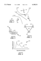
- FIG. 1 there is depicted a wireless communication system service area 100.
- subscriber unit 102 is located in the midst of base station antennas 104, 106, and 108.
- Angles of arrival for signals received at base station antennas 104, 106, and 108 are shown at reference numerals 110, 112, and 114, respectively.
- Locations in wireless communication service area 100 having a constant time difference of arrival may be shown as hyperbolas, such as hyperbolas 116, 118, 120, and 122.
- hyperbolas 116, 118, and 120 represent three distinctly different time differences measured between sites 104 and 106.
- the time difference between the propagation delay (or time of flight (TOF)) to antenna 104 and the propagation delay to antenna 106 is a constant.
- TOF time of flight
- hyperbola 122 represents another time difference contour measured between sites 106 and 108.
- hyperbola 122 represents another time difference contour measured between sites 106 and 108.
- Angle of arrival measurements may be made with sectorized antenna methods, such as shown in FIG. 2, or with a fixed beam array antenna, as shown in FIG. 3.
- Such fixed beam array antennas can form very narrow beams, which allows the angle of arrival to be determined with a much higher resolution.
- other methods known in the art such as adaptive beam forming and direction finding, even greater resolution may be obtained in determining the angle of arrival of a received signal.
- a set of antenna elements 130 is shown. Each antenna is connected to an input (4 inputs in this example) of a Butler Matrix.
- a Butler Matrix is commonly known in the art. Its function is to combine the inputs from the four antenna elements with the proper amplitudes and phases, to produce the effect of four distinct sector antennas pointing in four distinct directions. This technique may be referred to as "beam forming.”
- Outputs 132 represent the signals that would be received by the four "beam formed" sector antennas.
- the four different beams may provide a way to estimate the direction of an arriving signal by detecting the beam which had the first arrival of the received signal.
- FIG. 2 illustrates the use of fixed beam sectorized antennas arranged in different pointing directions.
- Antennas 134, 136, and 138 each point in a different direction, and by monitoring the signal level at their respective outputs, 140, 142, and 144, an estimate of the direction of arrival may be obtained as mentioned above.
- FIG. 1 illustrates a prior art time difference of arrival method of locating a subscriber in a non-cluttered area
- FIG. 2 depicts a set of sectorized antennas in accordance with the prior art
- FIG. 3 illustrates a narrow beam antenna array known in the prior art
- FIG. 4 shows a signal strength versus time delay profile, in accordance with the prior art
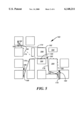
- FIG. 5 illustrates radio frequency signal propagation in a cluttered wireless communications system service area in accordance with the method and system of the present invention
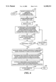
- FIG. 6 is a logic flowchart that illustrates the method and operation of estimating the location of a subscriber in a wireless communications system in accordance with the method and system of the present invention
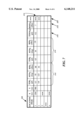
- FIG. 7 is a table of data that characterizes received signals in accordance with the method and system of the present invention.
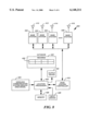
- FIG. 8 is a high level block diagram of a system for estimating the location of a subscriber in accordance with the present invention.
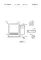
- FIG. 9 depicts a data processing system, which may be used to implement an embodiment of the method and system of the present invention.
- FIG. 5 there is depicted a model of a wireless communications system 160 in a dense urban area.
- subscriber unit 162 is located near buildings 164 in a downtown area, or other dense urban area.
- Base station antennas 166, 168, and 170 are located so that they may receive radio signals from subscriber 162.
- radio signal propagation paths between subscriber 162 and base station antennas 166-170 are shown as paths 172-180. As signals are received at base station antennas 166-170, each has an associated angle of arrival 182-190.
- angles of arrival 182, 186, and 188 do not necessarily point in the direction of subscriber unit 162.
- a time difference of arrival measurement would no longer represent a smooth hyperbolic contour of possible locations that represent a constant time difference between base sites. This is because the time difference in the urban environment is a function of the length of a specific indirect path, wherein signals following such an indirect path either reflect or diffract off of buildings. Such reflections and diffractions may change as a function of the subscriber's location.
- small changes in the subscriber's location may dramatically change the characteristics of the received signals in ways that are not apparent to a receiver using "clear path" rules for location finding.
- These changing signal characteristics include: propagation delay or time of flight (TOF), the angle of arrival (AOA), signal magnitude of the signal received at the base, the difference between magnitudes of signals measured at pairs of base sites, and the time difference of arrival (TDOA) measured between base site antennas.
- TOF propagation delay or time of flight
- AOA angle of arrival
- TDOA time difference of arrival
- the signal paths between the subscriber and the base stations that represent the shortest paths, that is, the first arrival of the signal energy in time, are illustrated by paths 172, 176, and 178, which are shown with solid lines. Additional paths, such as paths 174 and 180 shown with dashed lines, travel further. These additional paths are longer and thus have more time delay than the first-arriving paths.
- a power delay profile 148 This is a profile in time wherein the signal magnitude is plotted as a function of time.
- the first-arriving signal or ray is shown by the first peak 150. This ray is also the strongest ray in this example. Secondary rays are also evident, as shown at peaks 152 and 154.
- the first-arriving ray is the ray which has traveled the shortest path. Most location systems make use of this ray in the calculation of time and angle of arrival parameters. However, the present invention may use all rays, including secondary rays, in its location-finding calculations.
- FIG. 5 illustrates a very dense, high-rise environment where practically all signal propagation paths are reflected down the streets and diffracted around corners.
- path 174 includes a reflection 194 off of the side of a building 164. If shorter buildings are present, and taller base sites are used, many of the signal paths would travel over the rooftops of some buildings. This is not seen in this example, but by using three-dimensional predictions, over rooftop paths can also be used in location-finding calculations.
- FIG. 6 there is depicted a logic flowchart that illustrates the method and operation of estimating the location of a subscriber unit in a wireless communications system in accordance with the method and system of the present invention.
- the process begins at block 300, and thereafter passes to block 302 wherein a model of the wireless communications system service area is selected.
- a model is a two-dimensional representation of buildings and other structures that may reflect, diffract, or otherwise affect a radio frequency signal transmitted by a subscriber unit.
- such a model includes the location of base station antennas in the service area.
- An example of such a model is shown in FIG. 5, wherein buildings 164 are located relative to one another, and base station antennas 166-170 are also located relative to buildings 164.
- the process divides the service area model into tiles, as illustrated at block 304.
- tiles represent a small area in the service area, such as a 5 meter by 5 meter square.
- the size of the tile depends upon the required resolution of the location estimate. Rough location estimates having a lower resolution may be made using larger tiles; more accurate, higher resolution location estimates may be made using smaller tiles.
- the process selects a first tile, as depicted at block 306. Using this first tile, the process calculates signal characteristics associated with the reception of a model signal transmitted by a subscriber unit located in the selected tile, as illustrated at block 308. Such signal characteristic calculations are made for signals received at each base station antenna located in the model. These signal characteristic calculations are preferably made using known ray-tracing techniques that model reflections and diffractions of propagating radio frequency signals. Such signal characteristics calculated at each base station antenna location may include angle of arrival (AOA), time of flight (TOF) and received signal strength (RSS). For some tiles, it may be determined that a subscriber signal cannot be received at a particular base station because the signal is reflected or otherwise attenuated. If calculations indicate that more than one base station antenna can receive the subscriber's signal, other data may be calculated, such as time difference of arrival (TDOA) between pairs of receiving antennas and received signal strength difference (RSSD) between pairs of receiving antennas.
- TDOA time difference of arrival
- RSSD received signal strength difference
- Received signal strength is directly related to the power level of the subscriber's transmit signal. Measurements of received signal strength can be scaled if the subscriber's transmit power is set to a value different than a nominal value. In most cases, the subscriber's power level is known by base station controller 418, and can be used to adjust the values of the measured signals. In cases where the base station controller does not know the value of the subscriber's power level, a relative receive signal strength must be used. This is done by calculating the difference between received signal levels at pairs of bases, in a manner similar to the calculation of time difference of arrival. By using this difference method, the absolute transmit level is not needed.
- Time of flight is described in the preferred embodiment as a possible input parameter and included in database 208, FIG. 7.
- time of flight is difficult to measure, and therefore time difference of arrival is used since an absolute reference is not needed for this measurement.
- TOF may not be needed in 208, except for use in calculating the TDOA values.
- the process may also calculate signal characteristics for a later-received model signal. Such later-received signals follow other, longer paths before reaching the base antenna.
- each record 210 is associated with a tile in model 160 (see FIG. 5).
- a tile may be associated with more than one record because characteristics of later-arriving signals from that tile may also be recorded in database 208.
- fields 212 are associated with a first base station antenna location, such as base station antenna 166 (see FIG. 5).
- Fields 214 are associated with a second base station antenna, such as base station antenna 168 (also in FIG. 5).
- Fields associated with each antenna location may include: time of flight (TOF), measured in microseconds; angle of arrival (AOA), measured in degrees; and received signal strength (RSS), measured in decibels referenced to 1 milliwatt (dBm).
- TOF time of flight
- AOA angle of arrival
- RSS received signal strength
- a time difference of arrival and a received signal strength difference may also be calculated, as shown in fields 216 and 218. Similar data for other base station antenna locations may be stored in additional fields 220.
- the process next determines if there are additional tiles to be used in calculating signal characteristics, as illustrated at block 312. If there are additional tiles to be used in signal characteristic calculation, the process selects a next tile, as depicted at block 314, and then iteratively returns to block 308 to perform such calculations.
- the process next measures actual signal characteristics of a subscriber signal received at the base station antennas, as illustrated at block 316.
- the measured characteristics preferably include signal characteristics similar to those stored in database 208.
- the measured characteristics include: time of flight (TOF), angle of arrival (AOA), and received signal strength (RSS). If a signal is measured at more than one base station antenna, a time difference of arrival (TDOA) and a received signal strength difference (RSSD) may be calculated for pairs of base station antennas receiving the subscriber's signal.
- TDOA time difference of arrival
- RSSD received signal strength difference
- Signal characteristics may be measured for signals other than the first-arriving signal at each base station antenna. In a preferred embodiment, such signal characteristic measurements are made with an antenna array.
- Such an antenna array may be either a fixed beam array or an adaptive beam array.
- An adaptive beam antenna array can provide the most accurate direction of arrival measurement. Using a fixed beam array, direction of arrival may be determined by examining the proportional relation of received signal strengths over the various beams.
- Signal characteristic measurements may also be made using sectorized antennas, wherein the angle of arrival is estimated in a manner similar to that performed in the fixed beamed antenna array.
- the present invention may be implemented with omnidirectional base station antennas. If omnidirectional antennas are used, the number of calculated and measured signal characteristics should be sufficient enough to uniquely describe a signal transmitted from every tile in the service area. In order to calculate and measure a sufficient amount of data, calculations and measurements for additional base stations may be used. For example, measurements and calculations relating to base stations somewhat removed from the urban area may be used to uniquely identify signals transmitted from a selected tile. Thus, by including calculations and measurements for additional base stations, the values in the record associated with each tile will be different from the values in records associated with every other tile in the service area.
- the process determines a relationship between the measured signal characteristics and the calculated signal characteristics stored in the database, as depicted at block 318.
- a relationship is a root mean square (RMS) error relationship, which is calculated by the following formula: ##EQU1## where A n ,i, B n , C n ,i, are weighting function coefficients, which may be specified by base site, and m is the total number of base sites in the service area;
- RMS root mean square
- TODA i ,j is the calculated time difference of arrival between base i and base j;
- p -- TODA i ,j is the predicted value of the time difference of arrival between base i and base j, for a given tile
- AOA n is the measured angle of arrival at base site n
- p -- AOA n is the predicted angle of arrival at base site n for a given tile
- P n ,i is a parameter representing the measured received signal strength difference (RSSD) between received signal strengths (RSS) at base i and base j;
- p -- P n ,i is a parameter representing the predicted received signal strength difference (RSSD) between received signal strengths (RSS) at base i and base j;
- a n ,i, B n , C n ,i are coefficients used as weighting functions so that the accuracy and sensitivity of each of the parameters can be adjusted to give the most accurate and robust performance for the RMS error parameter calculation.
- These coefficients are specified as a function of the base site by the user, so that base site specific factors can be adjusted both in a relative and an absolute sense.
- These weighting factors may also be specified as a function of a particular title, so that base station antenna specific factors can be adjusted both for the entire cell and for a particular tile.
- the step of determining a relationship between measured signal characteristics and calculated signal characteristics may take into account such later-arriving rays.
- the RMS error calculation may include separate terms for calculated and measured later-arriving rays.
- the analysis of the later-arriving rays may also be weighted by appropriate weighting coefficients so that such rays are appropriately considered in the analysis.
- the process estimates the subscriber location based upon the relationship between the measured characteristics and the calculated characteristics, as illustrated at block 320.
- the location estimate corresponds to the location of the tile having the lowest RMS error, as determined in block 318.
- the estimated subscriber location is the x-y coordinate of the tile that has the lowest RMS error relationship with the measured subscriber signal.
- the location estimate is output, which may include printing or displaying the estimate on a computer screen, as depicted at block 322. Thereafter, the process terminates, as illustrated at block 324.
- the process may interpolate between records 210 (see FIG. 7) that have similar RMS error relationships with the measured signal. Such interpolation may improve the x-y coordinate estimate, and thereby provide an estimate with a greater resolution.
- the estimating step shown in block 320 may further include an averaging function which may average several sequential location estimates together in order to reduce spurious effects of noise.
- actual signal measurements of signals transmitted from known locations may be used to improve the method of calculating the calculated signal characteristics. For example, an actual measurement may determine that a base station antenna consistently measures an angle of arrival with a 5 degree error. This error may be taken into account and compensated for during the calculation process. Actual measurements may also aid in making adjustments to the service area model so that the reflectivity of buildings and other parameters may be adjusted in the ray-tracer.
- Signal characteristics may also be calculated using a trained neural network to predict signal characteristics of signals received from particular tiles.
- a neural network may be trained with actual signal measurements made in the service area. This method of calculating signal characteristics in a neural network may prove particularly important for service areas where environmental specifics needed by the ray-tracer are difficult to obtain, or where measurement validation techniques are difficult, such as inside buildings.
- location system 400 includes base stations 402-408. Each base station 402-408 is coupled to a base station antenna 410-416, respectively.
- antennas 410-416 are adapted to determine an angle of arrival of a radio frequency signal transmitted from a subscriber unit.
- Antenna systems having this capability include adaptive array antennas, which are able to form an antenna pattern that aids in the determination of the angle of arrival.
- antennas 410-416 may also be implemented with omnidirectional antennas.
- Antennas 410-416 are typically evenly dispersed throughout the communication system coverage area in order to provide service over the entire area.
- Base stations 402-408 are coupled to base station controller 418, which may be centrally located relative to base stations 402-408.
- Base station controller 418 is responsible for controlling base station operation, and other functions such as handoffs between base stations.
- location processor 420 is coupled to base station controller 418 for passing signal characteristic data and control data.
- Location processor 420 may be implemented with a general purpose data processing system, such as an HP 9000 Series 700 Model 735 workstation made by Hewlett-Packard Company, Palo Alto, Calif.
- location processor 420 is coupled database 422, wireless communication system service area model 424, memory 426, input device 428, and output device 430.
- Database 422 is used for storing records of calculated signal characteristics which may be received at base station antennas throughout the service area. Database 422 is described more completely with reference to FIG. 7.
- Wireless communication system service area model 424 includes data describing the location of buildings (and other objects affecting radio frequency propagation) and the location of base station antennas. This service area model 424 is used to predict signal propagation and calculate signal characteristics of a model signal transmitted from a selected tile and received at each base station antenna location.
- Memory 426 may, among other things, be used to store weighting function coefficients, which may be used to adjust certain parameters in the signal characteristic calculation process.
- Input device 428 is used to input data, weighting function coefficients, a service area model, or to update information regarding changes in the service area model.
- Input device 428 may be implemented with a disk drive unit, keyboard, or other means for in putting data.
- Output device 430 is used to display the location estimate.
- Output device 430 may be implemented with a display, which displays the coordinates of the subscriber unit, and which may also display a map of the service area with an indication of the location of the subscriber unit.
- Data processing system 450 may include processor 452, keyboard 454, display 456, and pointing device 458.
- Keyboard 454 provides means for entering data and commands into processor 452.
- Display 456 may be implemented utilizing any known means for displaying textual, graphical, or video images, such as a cathode ray tube (CRT), a liquid crystal display (LCD), an electroluminescent panel, or the like.
- Pointing device 458 may be implemented utilizing any known pointing device, such as a trackball, joystick, touch sensitive tablet or screen, track pad, or as illustrated in FIG. 5, a mouse. Pointing device 458 may be utilized to move a pointer or a cursor on display 456.
- Processor 452 may be coupled to one or more peripheral devices, such as CD-ROM 460.
- Data processing system 450 includes means for reading data from a storage device.
- Such means for reading data may include: a hard disk drive internal or external to processor 452 (not shown); a tape drive (not shown); floppy disk drive 462, which reads and writes floppy disks 464; or CD-ROM 460, which reads and/or writes compact disk 466.
- Such storage means may be referred to as a computer usable medium for storing computer readable program code in the form of data and software.
- Data processing system 450 may also be coupled to a network which permits the transfer of data and software between data processing systems. Using such a network, programs can be loaded into data processing system 450.
- data processing system 450 may each be implemented utilizing any one of several known off-the-shelf components.
- data processing system 450 may be implemented utilizing any general purpose computer or so-called workstation, such as the workstation sold under the name "HP 9000 Series 700 Model 735" by Hewlett-Packard Company of Palo Alto, Calif.
- the method and system of the present invention estimates the location of the subscriber unit in a wireless communications system service area.
- the present invention is especially useful for estimating location in a dense urban area, such as a downtown area including many high-rise buildings.
- Finding a subscriber location in a dense urban area involves careful analysis of indirect signals, wherein such an indirect signal has been reflected or diffracted, and does not travel in a straight path.
- Such indirect signals may not arrive from the direction of the transmitting subscriber unit.
- Such indirect signals have traveled a distance greater than the straight line distance between the subscriber unit and the base station antenna.
- both angle of arrival and time of flight erroneously indicate a location when "clear path" rules for determining location are used.
- a further advantage of the present invention is that the data in the database is calculated rather than empirically measured. Empirical measure of such received signals is time consuming, costly, and subject to human error.
- a three-dimensional service area model may also be used in order to determine a subscriber location in three dimensions.
- a location system may be able to locate a subscriber at, say, the fifth floor of a building at Main and First streets.
- a three-dimensional location system may be implemented using base stations having antennas that are adapted to measure a vertical angle of a received signal.
- base station antennas located at various heights above street level may be sampled so that angle of arrival and time measurements are three-dimensional in nature.
- additional fields may be used to store such height or vertical angle information.
Abstract
Description
Claims (30)
Priority Applications (9)
| Application Number | Priority Date | Filing Date | Title |
|---|---|---|---|
| US08/924,151 US6148211A (en) | 1997-09-05 | 1997-09-05 | Method and system for estimating a subscriber's location in a cluttered area |
| IL13457498A IL134574A (en) | 1997-09-05 | 1998-09-02 | Method and system for estimating a subscriber's location in a cluttered area |
| BRPI9811626-6A BR9811626B1 (en) | 1997-09-05 | 1998-09-02 | Method and system for locating a subscriber unit in a Wireless Communication System Service Area. |
| JP2000511318A JP2001516999A (en) | 1997-09-05 | 1998-09-02 | Method and system for estimating subscriber position under radio wave scattering environment |
| PCT/US1998/018159 WO1999013662A1 (en) | 1997-09-05 | 1998-09-02 | Method and system for estimating a subscriber's location in a cluttered area |
| CA002302502A CA2302502C (en) | 1997-09-05 | 1998-09-02 | Method and system for estimating a subscriber's location in a cluttered area |
| KR1020007002358A KR100366326B1 (en) | 1997-09-05 | 1998-09-02 | Method and system for estimating a subscriber's location in a cluttered area |
| CNB988088525A CN1202678C (en) | 1997-09-05 | 1998-09-02 | Method and system for estimating subscriber's location in cluttered area |
| EP98941124A EP1008265A4 (en) | 1997-09-05 | 1998-09-02 | Method and system for estimating a subscriber's location in a cluttered area |
Applications Claiming Priority (1)
| Application Number | Priority Date | Filing Date | Title |
|---|---|---|---|
| US08/924,151 US6148211A (en) | 1997-09-05 | 1997-09-05 | Method and system for estimating a subscriber's location in a cluttered area |
Publications (1)
| Publication Number | Publication Date |
|---|---|
| US6148211A true US6148211A (en) | 2000-11-14 |
Family
ID=25449783
Family Applications (1)
| Application Number | Title | Priority Date | Filing Date |
|---|---|---|---|
| US08/924,151 Expired - Lifetime US6148211A (en) | 1997-09-05 | 1997-09-05 | Method and system for estimating a subscriber's location in a cluttered area |
Country Status (9)
| Country | Link |
|---|---|
| US (1) | US6148211A (en) |
| EP (1) | EP1008265A4 (en) |
| JP (1) | JP2001516999A (en) |
| KR (1) | KR100366326B1 (en) |
| CN (1) | CN1202678C (en) |
| BR (1) | BR9811626B1 (en) |
| CA (1) | CA2302502C (en) |
| IL (1) | IL134574A (en) |
| WO (1) | WO1999013662A1 (en) |
Cited By (43)
| Publication number | Priority date | Publication date | Assignee | Title |
|---|---|---|---|---|
| WO2001050786A1 (en) * | 1999-12-30 | 2001-07-12 | Motorola, Inc. | Method and system for creating a rf signature for a signature region in a wireless communication system |
| WO2001050785A1 (en) * | 1999-12-30 | 2001-07-12 | Motorola, Inc. | Method and system for comparing measured radio frequency signal propagation characteristics in a wireless communication system |
| US6282426B1 (en) * | 1999-06-08 | 2001-08-28 | Nokia Mobile Phones Limited | Method, and associated apparatus, for determining geographic positioning of a wireless communication station operable in a non-ideal propagation environment |
| US6397073B1 (en) * | 1997-10-03 | 2002-05-28 | Nokia Networks Oy | Method of locating terminal, and cellular radio system |
| US20020089722A1 (en) * | 2001-01-05 | 2002-07-11 | Perkins Matthew R. | Optically-based location system and method for determining a location at a structure |
| US6507742B1 (en) * | 1999-11-11 | 2003-01-14 | Ericsson Inc. | Automatic color code (SAT) assignment method used in frequency planning for wireless networks |
| WO2003017694A1 (en) * | 2001-08-15 | 2003-02-27 | Motorola Inc. | Determining a location relevant to a communication device |
| US6542733B1 (en) * | 1998-10-15 | 2003-04-01 | Openwave Technologies Inc | System and method for controlling personal telephone number dialing lists and dialing capabilities |
| US20030063589A1 (en) * | 2001-09-28 | 2003-04-03 | Haines Robert E. | Locating and mapping wireless network devices via wireless gateways |
| US6580910B1 (en) * | 1997-12-19 | 2003-06-17 | Telefonaktiebolaget L M Ericsson (Publ) | Method and system for improving handoffs in cellular mobile radio systems |
| US6603428B2 (en) * | 1999-01-08 | 2003-08-05 | Trueposition, Inc. | Multiple pass location processing |
| US20040017312A1 (en) * | 1999-01-08 | 2004-01-29 | Anderson Robert J. | Multiple pass location processor |
| EP1059008A4 (en) * | 1998-02-27 | 2004-08-18 | Motorola Inc | Method and system for estimating a subscriber's location in a wireless communication system service area |
| US20040174297A1 (en) * | 2003-03-06 | 2004-09-09 | Samsung Electronics Co. Ltd. | Hybird navigation system using neural network |
| US20050014497A1 (en) * | 2003-05-23 | 2005-01-20 | Goren David P. | Method for tracking location of a mobile unit |
| US20050032531A1 (en) * | 2003-08-06 | 2005-02-10 | Hong Kong Applied Science And Technology Research Institute Co., Ltd. | Location positioning in wireless networks |
| US20050105600A1 (en) * | 2003-11-14 | 2005-05-19 | Okulus Networks Inc. | System and method for location tracking using wireless networks |
| US20050130677A1 (en) * | 2003-12-12 | 2005-06-16 | Xerox Corporation | Mobile device and method for determining location of mobile device |
| US20050246334A1 (en) * | 2004-04-30 | 2005-11-03 | Hong Kong Applied Science And Technology Research Institute Co., Ltd. | Location determination and location tracking in wireless networks |
| FR2880693A1 (en) * | 2005-01-11 | 2006-07-14 | Pole Star Sarl | METHOD AND DEVICE FOR POSITIONING. |
| US20070032245A1 (en) * | 2005-08-05 | 2007-02-08 | Alapuranen Pertti O | Intelligent transportation system and method |
| US20070075900A1 (en) * | 2005-09-12 | 2007-04-05 | Lockheed Martin Corporation | System and method for determining the location of emitters having well-behaved timing features |
| US20070211620A1 (en) * | 2006-03-10 | 2007-09-13 | Motorola, Inc. | Method and apparatus for scheduling an acknowledgement transmission |
| US7783299B2 (en) | 1999-01-08 | 2010-08-24 | Trueposition, Inc. | Advanced triggers for location-based service applications in a wireless location system |
| US7797448B1 (en) * | 1999-10-28 | 2010-09-14 | Ernest G Szoke | GPS-internet linkage |
| US20110148709A1 (en) * | 2009-12-18 | 2011-06-23 | At&T Mobility Ii Llc | Signal path delay determination |
| US20110205053A1 (en) * | 2010-02-25 | 2011-08-25 | Qualcomm Incorporated | Method and apparatus for enhanced indoor position location with assisted user profiles |
| US8213957B2 (en) | 2009-04-22 | 2012-07-03 | Trueposition, Inc. | Network autonomous wireless location system |
| US20130244689A1 (en) * | 2012-03-13 | 2013-09-19 | Empire Technology Development Llc | Determining the position of a mobile device in an indoor environment |
| US8600674B1 (en) * | 2007-08-15 | 2013-12-03 | University Of South Florida | Using pattern recognition in real-time LBS applications |
| US20150023248A1 (en) * | 2013-07-19 | 2015-01-22 | Nec Laboratories America, Inc. | Multi-user multiple input multiple output (mimo) communication with distributed antenna systems in wireless networks |
| US20150148059A1 (en) * | 2013-11-26 | 2015-05-28 | At&T Intellectual Property I, L.P. | Time distance of arrival based mobile device location detection with disturbance scrutiny |
| US20150230100A1 (en) * | 2011-06-30 | 2015-08-13 | Aboelmagd Noureldin | System and method for wireless positioning in wireless network-enabled environments |
| US9142122B2 (en) | 2010-11-25 | 2015-09-22 | Panasonic Intellectual Property Corporation Of America | Communication device for performing wireless communication with an external server based on information received via near field communication |
| US9143933B2 (en) | 2008-12-26 | 2015-09-22 | Panasonic Intellectual Property Corporation Of America | Communication device that receives external device information from an external device using near field communication |
| US20150373663A1 (en) * | 2014-06-20 | 2015-12-24 | Samsung Electronics Co., Ltd. | Localization using converged platforms |
| USRE45980E1 (en) | 2009-11-30 | 2016-04-19 | Panasonic Intellectual Property Corporation Of America | Communication device |
| USRE46108E1 (en) | 2009-11-30 | 2016-08-16 | Panasonic Intellectual Property Corporation Of America | Communication device |
| US20160345287A1 (en) * | 2015-05-22 | 2016-11-24 | The Provost, Fellows, Foundation Scholars and the other members of Board, of the College of the Holy | Transmitter localization method and system based on the reciprocity theorem using signal strength measurements |
| EP3209063A4 (en) * | 2014-11-05 | 2017-11-08 | Huawei Technologies Co., Ltd. | Position information acquisition method and device |
| US20180267088A1 (en) * | 2015-09-29 | 2018-09-20 | Thales | Method for determining features of an electromagnetic wave |
| US10749754B2 (en) * | 2016-09-30 | 2020-08-18 | Huawei Technologies Co., Ltd. | Network distance prediction method and apparatus |
| FR3103903A1 (en) * | 2019-11-29 | 2021-06-04 | Orange | A method of locating a user of a terminal, a method of determining a location table, devices, access point, a user's terminal, system and associated computer programs. |
Families Citing this family (25)
| Publication number | Priority date | Publication date | Assignee | Title |
|---|---|---|---|---|
| DE19923638C2 (en) * | 1999-05-22 | 2002-01-10 | Univ Hannover | Method for managing the location of a mobile terminal in a cellular mobile radio network, cellular mobile radio network and mobile terminal |
| EP1124140A1 (en) * | 2000-02-08 | 2001-08-16 | Motorola, Inc. | Mobile telephone location system and method |
| DE10029115A1 (en) * | 2000-06-14 | 2001-12-20 | Mannesmann Ag | Method for determination of the traffic state within an area by detecting the movement of mobile phones between base stations in the area and comparing the signal travel times with previously calibrated times to determine position |
| EP1436639B1 (en) * | 2001-09-05 | 2007-06-20 | Newbury Networks Inc. | Position detection and location tracking in a wireless network |
| JP3784795B2 (en) * | 2003-10-10 | 2006-06-14 | 三菱電機株式会社 | TRACKING SYSTEM, MOBILE BODY TRACKING DEVICE, AND PROGRAM |
| JP3784794B2 (en) * | 2003-10-10 | 2006-06-14 | 三菱電機株式会社 | TRACKING SYSTEM, MOBILE BODY TRACKING DEVICE, AND PROGRAM |
| CN102685884B (en) * | 2003-11-21 | 2015-03-18 | 高通股份有限公司 | Estimating a position of a wireless mobile device with respect to one or more base stations |
| WO2006105619A1 (en) * | 2005-04-08 | 2006-10-12 | Seeker Wireless Pty Limited | Mobile location |
| KR100703292B1 (en) * | 2006-02-15 | 2007-04-03 | 삼성전자주식회사 | Appratus and method for detecting adaptive step |
| ATE540551T1 (en) | 2006-04-28 | 2012-01-15 | France Telecom | DETERMINATION OF A LOCALIZATION ZONE OF A TERMINAL DEVICE REGARDING A PARTICULAR GEOGRAPHICAL REGION |
| KR100954169B1 (en) * | 2008-02-27 | 2010-04-20 | 부산대학교 산학협력단 | TDOA based localization system, localization method in port logistics environment |
| KR101232705B1 (en) | 2008-06-27 | 2013-02-13 | 프라운호퍼 게젤샤프트 쭈르 푀르데룽 데어 안겐반텐 포르슝 에. 베. | Apparatus and method for allocating a current measurement value for a geographical position to a map object |
| US8892127B2 (en) | 2008-11-21 | 2014-11-18 | Qualcomm Incorporated | Wireless-based positioning adjustments using a motion sensor |
| US9645225B2 (en) | 2008-11-21 | 2017-05-09 | Qualcomm Incorporated | Network-centric determination of node processing delay |
| US20100135178A1 (en) | 2008-11-21 | 2010-06-03 | Qualcomm Incorporated | Wireless position determination using adjusted round trip time measurements |
| US9125153B2 (en) | 2008-11-25 | 2015-09-01 | Qualcomm Incorporated | Method and apparatus for two-way ranging |
| US8768344B2 (en) | 2008-12-22 | 2014-07-01 | Qualcomm Incorporated | Post-deployment calibration for wireless position determination |
| US8750267B2 (en) | 2009-01-05 | 2014-06-10 | Qualcomm Incorporated | Detection of falsified wireless access points |
| KR101301020B1 (en) * | 2009-12-16 | 2013-08-28 | 한국전자통신연구원 | A movable node position searching device and the position searching method thereof |
| CA2785283C (en) * | 2009-12-23 | 2018-07-10 | Sensewhere Limited | Locating electromagnetic signal sources |
| US8781492B2 (en) | 2010-04-30 | 2014-07-15 | Qualcomm Incorporated | Device for round trip time measurements |
| US8577392B1 (en) * | 2012-06-13 | 2013-11-05 | Apple Inc. | System and method of determining location of wireless communication devices/persons for controlling/adjusting operation of devices based on the location |
| WO2017199274A1 (en) * | 2016-05-19 | 2017-11-23 | Nec Corporation | Information processing apparatus, base station, information processing method and program |
| CN111970641B (en) * | 2020-07-28 | 2022-06-14 | 国网上海市电力公司 | Positioning tracking method based on TDOA |
| CN112859089A (en) * | 2021-01-14 | 2021-05-28 | 深圳市一指淘科技有限公司 | Real-time mobile positioning system for special-shaped space |
Citations (8)
| Publication number | Priority date | Publication date | Assignee | Title |
|---|---|---|---|---|
| US5218367A (en) * | 1992-06-01 | 1993-06-08 | Trackmobile | Vehicle tracking system |
| US5299132A (en) * | 1991-01-17 | 1994-03-29 | By-Word Technologies, Inc. | Vehicle locating and communicating method and apparatus using cellular telephone network |
| US5600706A (en) * | 1992-04-08 | 1997-02-04 | U S West, Inc. | Method and system for determining the position of a mobile receiver |
| US5602903A (en) * | 1994-09-28 | 1997-02-11 | Us West Technologies, Inc. | Positioning system and method |
| US5623429A (en) * | 1994-04-06 | 1997-04-22 | Lucent Technologies Inc. | Techniques for expeditiously predicting electromagnetic wave propagation |
| US5673305A (en) * | 1993-05-14 | 1997-09-30 | Worldwide Notification Systems, Inc. | Apparatus and method for tracking and reporting the location of a motor vehicle |
| US5732354A (en) * | 1995-06-07 | 1998-03-24 | At&T Wireless Services, Inc. | Method and apparatus for determining the location of a mobile telephone |
| US5742666A (en) * | 1994-10-05 | 1998-04-21 | Tele Digital Development, Inc. | Emergency mobile telephone |
Family Cites Families (9)
| Publication number | Priority date | Publication date | Assignee | Title |
|---|---|---|---|---|
| US5327144A (en) * | 1993-05-07 | 1994-07-05 | Associated Rt, Inc. | Cellular telephone location system |
| JPH07170564A (en) * | 1993-12-15 | 1995-07-04 | Mitsubishi Electric Corp | Controlling method for mobile telephone system and mobile telephone set |
| JP2868113B2 (en) * | 1994-02-21 | 1999-03-10 | エヌ・ティ・ティ移動通信網株式会社 | Moving object position detection method by mobile communication |
| JP3399623B2 (en) * | 1994-03-16 | 2003-04-21 | 富士通株式会社 | Mobile station position acquisition device |
| JPH08107583A (en) * | 1994-10-05 | 1996-04-23 | Nippon Telegr & Teleph Corp <Ntt> | Method, system and device for detecting position of mobile station for mobile communication |
| JP3260991B2 (en) * | 1994-12-22 | 2002-02-25 | 京セラ株式会社 | Mobile Station Current Location Service Scheme for Cellular Telephone |
| EP0733912A2 (en) * | 1995-03-20 | 1996-09-25 | General Electric Company | Object location system |
| JP3117626B2 (en) * | 1995-10-25 | 2000-12-18 | 株式会社エヌ・ティ・ティ・ドコモ | Field strength calculation apparatus and field strength estimation method |
| JP2776784B2 (en) * | 1995-12-27 | 1998-07-16 | 日本電気移動通信株式会社 | Moving object position detection system |
-
1997
- 1997-09-05 US US08/924,151 patent/US6148211A/en not_active Expired - Lifetime
-
1998
- 1998-09-02 JP JP2000511318A patent/JP2001516999A/en active Pending
- 1998-09-02 BR BRPI9811626-6A patent/BR9811626B1/en not_active IP Right Cessation
- 1998-09-02 CA CA002302502A patent/CA2302502C/en not_active Expired - Fee Related
- 1998-09-02 CN CNB988088525A patent/CN1202678C/en not_active Expired - Fee Related
- 1998-09-02 KR KR1020007002358A patent/KR100366326B1/en not_active IP Right Cessation
- 1998-09-02 EP EP98941124A patent/EP1008265A4/en not_active Withdrawn
- 1998-09-02 IL IL13457498A patent/IL134574A/en not_active IP Right Cessation
- 1998-09-02 WO PCT/US1998/018159 patent/WO1999013662A1/en active IP Right Grant
Patent Citations (8)
| Publication number | Priority date | Publication date | Assignee | Title |
|---|---|---|---|---|
| US5299132A (en) * | 1991-01-17 | 1994-03-29 | By-Word Technologies, Inc. | Vehicle locating and communicating method and apparatus using cellular telephone network |
| US5600706A (en) * | 1992-04-08 | 1997-02-04 | U S West, Inc. | Method and system for determining the position of a mobile receiver |
| US5218367A (en) * | 1992-06-01 | 1993-06-08 | Trackmobile | Vehicle tracking system |
| US5673305A (en) * | 1993-05-14 | 1997-09-30 | Worldwide Notification Systems, Inc. | Apparatus and method for tracking and reporting the location of a motor vehicle |
| US5623429A (en) * | 1994-04-06 | 1997-04-22 | Lucent Technologies Inc. | Techniques for expeditiously predicting electromagnetic wave propagation |
| US5602903A (en) * | 1994-09-28 | 1997-02-11 | Us West Technologies, Inc. | Positioning system and method |
| US5742666A (en) * | 1994-10-05 | 1998-04-21 | Tele Digital Development, Inc. | Emergency mobile telephone |
| US5732354A (en) * | 1995-06-07 | 1998-03-24 | At&T Wireless Services, Inc. | Method and apparatus for determining the location of a mobile telephone |
Non-Patent Citations (2)
| Title |
|---|
| Internet web page describing RadioCamera made by U.S. Wireless Corporation, Labyrinth Communications Group, Inc. . * |
| Internet web page describing RadioCamera™ made by U.S. Wireless Corporation, "Labyrinth Communications Group, Inc.". |
Cited By (91)
| Publication number | Priority date | Publication date | Assignee | Title |
|---|---|---|---|---|
| US6397073B1 (en) * | 1997-10-03 | 2002-05-28 | Nokia Networks Oy | Method of locating terminal, and cellular radio system |
| US6580910B1 (en) * | 1997-12-19 | 2003-06-17 | Telefonaktiebolaget L M Ericsson (Publ) | Method and system for improving handoffs in cellular mobile radio systems |
| EP1059008A4 (en) * | 1998-02-27 | 2004-08-18 | Motorola Inc | Method and system for estimating a subscriber's location in a wireless communication system service area |
| US6542733B1 (en) * | 1998-10-15 | 2003-04-01 | Openwave Technologies Inc | System and method for controlling personal telephone number dialing lists and dialing capabilities |
| US8320931B2 (en) | 1999-01-08 | 2012-11-27 | Trueposition, Inc. | Geo-fencing in a wireless location system |
| US20040017312A1 (en) * | 1999-01-08 | 2004-01-29 | Anderson Robert J. | Multiple pass location processor |
| US7783299B2 (en) | 1999-01-08 | 2010-08-24 | Trueposition, Inc. | Advanced triggers for location-based service applications in a wireless location system |
| US6873290B2 (en) * | 1999-01-08 | 2005-03-29 | Trueposition, Inc. | Multiple pass location processor |
| US7271765B2 (en) | 1999-01-08 | 2007-09-18 | Trueposition, Inc. | Applications processor including a database system, for use in a wireless location system |
| US9288628B2 (en) | 1999-01-08 | 2016-03-15 | Trueposition, Inc. | Advanced triggers for location-based service applications in a wireless location system |
| US6603428B2 (en) * | 1999-01-08 | 2003-08-05 | Trueposition, Inc. | Multiple pass location processing |
| US20050024265A1 (en) * | 1999-01-08 | 2005-02-03 | Trueposition, Inc. | Multiple pass location processor |
| US20050206566A1 (en) * | 1999-01-08 | 2005-09-22 | True Position, Inc. | Multiple pass location processor |
| USRE42285E1 (en) | 1999-01-08 | 2011-04-12 | Trueposition, Inc. | Applications processor including a database system, for use in a wireless location system |
| US8509805B2 (en) | 1999-01-08 | 2013-08-13 | Trueposition, Inc. | Advanced triggers for location-based service applications in a wireless location system |
| US7023383B2 (en) | 1999-01-08 | 2006-04-04 | Trueposition, Inc. | Multiple pass location processor |
| US8838139B2 (en) | 1999-01-08 | 2014-09-16 | Trueposition, Inc. | Advanced triggers for location-based service applications in a wireless location system |
| US6282426B1 (en) * | 1999-06-08 | 2001-08-28 | Nokia Mobile Phones Limited | Method, and associated apparatus, for determining geographic positioning of a wireless communication station operable in a non-ideal propagation environment |
| US7797448B1 (en) * | 1999-10-28 | 2010-09-14 | Ernest G Szoke | GPS-internet linkage |
| US6507742B1 (en) * | 1999-11-11 | 2003-01-14 | Ericsson Inc. | Automatic color code (SAT) assignment method used in frequency planning for wireless networks |
| WO2001050785A1 (en) * | 1999-12-30 | 2001-07-12 | Motorola, Inc. | Method and system for comparing measured radio frequency signal propagation characteristics in a wireless communication system |
| WO2001050786A1 (en) * | 1999-12-30 | 2001-07-12 | Motorola, Inc. | Method and system for creating a rf signature for a signature region in a wireless communication system |
| US6865347B2 (en) * | 2001-01-05 | 2005-03-08 | Motorola, Inc. | Optically-based location system and method for determining a location at a structure |
| US20020089722A1 (en) * | 2001-01-05 | 2002-07-11 | Perkins Matthew R. | Optically-based location system and method for determining a location at a structure |
| WO2003017694A1 (en) * | 2001-08-15 | 2003-02-27 | Motorola Inc. | Determining a location relevant to a communication device |
| US6757544B2 (en) * | 2001-08-15 | 2004-06-29 | Motorola, Inc. | System and method for determining a location relevant to a communication device and/or its associated user |
| US20030063589A1 (en) * | 2001-09-28 | 2003-04-03 | Haines Robert E. | Locating and mapping wireless network devices via wireless gateways |
| US6826162B2 (en) * | 2001-09-28 | 2004-11-30 | Hewlett-Packard Development Company, L.P. | Locating and mapping wireless network devices via wireless gateways |
| US6919842B2 (en) * | 2003-03-06 | 2005-07-19 | Samsung Electronics Co., Ltd. | Hybrid navigation system using neural network |
| US20040174297A1 (en) * | 2003-03-06 | 2004-09-09 | Samsung Electronics Co. Ltd. | Hybird navigation system using neural network |
| CN1795396B (en) * | 2003-04-15 | 2010-11-03 | 真实定位公司 | Multiple pass location processor |
| WO2004092762A1 (en) * | 2003-04-15 | 2004-10-28 | Trueposition, Inc. | Multiple pass location processor |
| GB2417845B (en) * | 2003-04-15 | 2007-05-30 | Trueposition Inc | Multiple pass location processor |
| GB2417845A (en) * | 2003-04-15 | 2006-03-08 | Trueposition Inc | Multiple pass location processor |
| US7424300B2 (en) * | 2003-05-23 | 2008-09-09 | Symbol Technologies, Inc. | Method for tracking location of a mobile unit |
| US7873368B2 (en) * | 2003-05-23 | 2011-01-18 | Symbol Technologies, Inc. | Method for tracking location of a mobile unit |
| US20050014497A1 (en) * | 2003-05-23 | 2005-01-20 | Goren David P. | Method for tracking location of a mobile unit |
| US20090047975A1 (en) * | 2003-05-23 | 2009-02-19 | Goren David P | Method for Tracking Location of a Mobile Unit |
| US20050032531A1 (en) * | 2003-08-06 | 2005-02-10 | Hong Kong Applied Science And Technology Research Institute Co., Ltd. | Location positioning in wireless networks |
| US7313403B2 (en) * | 2003-08-06 | 2007-12-25 | Hong Kong Applied Science And Technology Research Institute Co., Ltd. | Location positioning in wireless networks |
| US20050105600A1 (en) * | 2003-11-14 | 2005-05-19 | Okulus Networks Inc. | System and method for location tracking using wireless networks |
| US7042391B2 (en) * | 2003-12-12 | 2006-05-09 | Xerox Corporation | Mobile device and method for determining location of mobile device |
| US20050130677A1 (en) * | 2003-12-12 | 2005-06-16 | Xerox Corporation | Mobile device and method for determining location of mobile device |
| US20050246334A1 (en) * | 2004-04-30 | 2005-11-03 | Hong Kong Applied Science And Technology Research Institute Co., Ltd. | Location determination and location tracking in wireless networks |
| US7359718B2 (en) * | 2004-04-30 | 2008-04-15 | Hong Kong Applied Science And Technology Research Institute Co., Ltd. | Location determination and location tracking in wireless networks |
| WO2006075116A1 (en) * | 2005-01-11 | 2006-07-20 | Pole Star | Positioning device and method |
| US20080129598A1 (en) * | 2005-01-11 | 2008-06-05 | Baptiste Godefroy | Positioning Method and Device |
| FR2880693A1 (en) * | 2005-01-11 | 2006-07-14 | Pole Star Sarl | METHOD AND DEVICE FOR POSITIONING. |
| US20070032245A1 (en) * | 2005-08-05 | 2007-02-08 | Alapuranen Pertti O | Intelligent transportation system and method |
| US20070075900A1 (en) * | 2005-09-12 | 2007-04-05 | Lockheed Martin Corporation | System and method for determining the location of emitters having well-behaved timing features |
| US7342536B2 (en) * | 2005-09-12 | 2008-03-11 | Lockheed Martin Corporation | System and method for determining the location of emitters having well-behaved timing features |
| US20070211620A1 (en) * | 2006-03-10 | 2007-09-13 | Motorola, Inc. | Method and apparatus for scheduling an acknowledgement transmission |
| WO2007106656A2 (en) * | 2006-03-10 | 2007-09-20 | Motorola, Inc. | Method and apparatus for scheduling an acknowledgement transmission |
| WO2007106656A3 (en) * | 2006-03-10 | 2008-02-21 | Motorola Inc | Method and apparatus for scheduling an acknowledgement transmission |
| US8194696B2 (en) | 2006-03-10 | 2012-06-05 | Motorola Mobility, Inc. | Method and apparatus for scheduling an acknowledgement transmission |
| US8600674B1 (en) * | 2007-08-15 | 2013-12-03 | University Of South Florida | Using pattern recognition in real-time LBS applications |
| US8751162B1 (en) * | 2007-08-15 | 2014-06-10 | University Of South Florida | System for pattern recognition in real-time location-based services applications |
| US9143933B2 (en) | 2008-12-26 | 2015-09-22 | Panasonic Intellectual Property Corporation Of America | Communication device that receives external device information from an external device using near field communication |
| US8213957B2 (en) | 2009-04-22 | 2012-07-03 | Trueposition, Inc. | Network autonomous wireless location system |
| USRE46108E1 (en) | 2009-11-30 | 2016-08-16 | Panasonic Intellectual Property Corporation Of America | Communication device |
| USRE45980E1 (en) | 2009-11-30 | 2016-04-19 | Panasonic Intellectual Property Corporation Of America | Communication device |
| US8174446B2 (en) * | 2009-12-18 | 2012-05-08 | At&T Mobility Ii Llc | Signal path delay determination |
| US7990317B2 (en) * | 2009-12-18 | 2011-08-02 | At&T Mobility Ii Llc | Signal path delay determination |
| US20110148709A1 (en) * | 2009-12-18 | 2011-06-23 | At&T Mobility Ii Llc | Signal path delay determination |
| US20110205053A1 (en) * | 2010-02-25 | 2011-08-25 | Qualcomm Incorporated | Method and apparatus for enhanced indoor position location with assisted user profiles |
| US9058732B2 (en) * | 2010-02-25 | 2015-06-16 | Qualcomm Incorporated | Method and apparatus for enhanced indoor position location with assisted user profiles |
| US9262913B2 (en) | 2010-11-25 | 2016-02-16 | Panasonic Intellectual Property Corporation Of America | Communication device |
| US9142122B2 (en) | 2010-11-25 | 2015-09-22 | Panasonic Intellectual Property Corporation Of America | Communication device for performing wireless communication with an external server based on information received via near field communication |
| US20150230100A1 (en) * | 2011-06-30 | 2015-08-13 | Aboelmagd Noureldin | System and method for wireless positioning in wireless network-enabled environments |
| US10349286B2 (en) * | 2011-06-30 | 2019-07-09 | Invensense, Inc. | System and method for wireless positioning in wireless network-enabled environments |
| US9055396B2 (en) * | 2012-03-13 | 2015-06-09 | Empire Technology Development Llc | Determining the position of a mobile device in an indoor environment |
| US9288634B2 (en) | 2012-03-13 | 2016-03-15 | Empire Technology Development Llc | Determining the position of a mobile device in an indoor environment |
| US20130244689A1 (en) * | 2012-03-13 | 2013-09-19 | Empire Technology Development Llc | Determining the position of a mobile device in an indoor environment |
| US9712979B2 (en) | 2012-03-13 | 2017-07-18 | Empire Technology Development Llc | Determining the position of a mobile device in an indoor environment |
| US20150023248A1 (en) * | 2013-07-19 | 2015-01-22 | Nec Laboratories America, Inc. | Multi-user multiple input multiple output (mimo) communication with distributed antenna systems in wireless networks |
| US9450654B2 (en) * | 2013-07-19 | 2016-09-20 | Nec Corporation | Multi-user multiple input multiple output (MIMO) communication with distributed antenna systems in wireless networks |
| US9967854B2 (en) | 2013-11-26 | 2018-05-08 | At&T Intellectual Property I, L.P. | Time distance of arrival based mobile device location detection with disturbance scrutiny |
| US20150148059A1 (en) * | 2013-11-26 | 2015-05-28 | At&T Intellectual Property I, L.P. | Time distance of arrival based mobile device location detection with disturbance scrutiny |
| US10375668B2 (en) * | 2013-11-26 | 2019-08-06 | At&T Intellectual Property I, L.P. | Time distance of arrival based mobile device location detection with disturbance scrutiny |
| US9538494B2 (en) * | 2013-11-26 | 2017-01-03 | At&T Intellectual Property I, L.P. | Time distance of arrival based mobile device location detection with disturbance scrutiny |
| US9781697B2 (en) * | 2014-06-20 | 2017-10-03 | Samsung Electronics Co., Ltd. | Localization using converged platforms |
| US20150373663A1 (en) * | 2014-06-20 | 2015-12-24 | Samsung Electronics Co., Ltd. | Localization using converged platforms |
| US9913097B2 (en) | 2014-11-05 | 2018-03-06 | Huawei Technologies Co., Ltd. | Method and apparatus for obtaining location information |
| EP3209063A4 (en) * | 2014-11-05 | 2017-11-08 | Huawei Technologies Co., Ltd. | Position information acquisition method and device |
| AU2014410620B2 (en) * | 2014-11-05 | 2018-07-05 | Huawei Technologies Co., Ltd. | Method and apparatus for obtaining location information |
| RU2665229C1 (en) * | 2014-11-05 | 2018-08-28 | Хуавей Текнолоджиз Ко., Лтд. | Method and device for obtaining location information |
| US20160345287A1 (en) * | 2015-05-22 | 2016-11-24 | The Provost, Fellows, Foundation Scholars and the other members of Board, of the College of the Holy | Transmitter localization method and system based on the reciprocity theorem using signal strength measurements |
| US20180267088A1 (en) * | 2015-09-29 | 2018-09-20 | Thales | Method for determining features of an electromagnetic wave |
| US10976401B2 (en) * | 2015-09-29 | 2021-04-13 | Thales | Method for determining features of an electromagnetic wave |
| US10749754B2 (en) * | 2016-09-30 | 2020-08-18 | Huawei Technologies Co., Ltd. | Network distance prediction method and apparatus |
| FR3103903A1 (en) * | 2019-11-29 | 2021-06-04 | Orange | A method of locating a user of a terminal, a method of determining a location table, devices, access point, a user's terminal, system and associated computer programs. |
Also Published As
| Publication number | Publication date |
|---|---|
| KR100366326B1 (en) | 2002-12-31 |
| BR9811626A (en) | 2000-09-19 |
| IL134574A (en) | 2004-06-20 |
| CN1202678C (en) | 2005-05-18 |
| CA2302502C (en) | 2004-07-27 |
| WO1999013662A1 (en) | 1999-03-18 |
| BR9811626B1 (en) | 2013-04-09 |
| EP1008265A4 (en) | 2003-07-16 |
| KR20010023704A (en) | 2001-03-26 |
| JP2001516999A (en) | 2001-10-02 |
| IL134574A0 (en) | 2001-04-30 |
| CN1269947A (en) | 2000-10-11 |
| EP1008265A1 (en) | 2000-06-14 |
| CA2302502A1 (en) | 1999-03-18 |
Similar Documents
| Publication | Publication Date | Title |
|---|---|---|
| US6148211A (en) | Method and system for estimating a subscriber's location in a cluttered area | |
| US6161018A (en) | Method and system for estimating a subscriber's location in a wireless communication system service area | |
| JP5102386B2 (en) | Method and apparatus for simulating and planning a wireless positioning network | |
| US8909245B2 (en) | System and method for estimating positioning error within a WLAN-based positioning system | |
| US6408186B1 (en) | Method of locating a mobile phone by measuring the distance between the phone and a base station in a cellular mobile telephone system | |
| US9237415B2 (en) | Method and system for estimating range of mobile device to wireless installation | |
| FI109241B (en) | Method and apparatus for positioning in telecommunication systems | |
| US7146298B2 (en) | System and method for wireless location performance prediction | |
| US20070049286A1 (en) | System and method for determining position of mobile communication device by grid-based pattern matching algorithm | |
| US20100137005A1 (en) | Method for positioning portable communication device | |
| JP2000244968A (en) | Method for deciding position of mobile station in radio communication system | |
| JP2013515952A (en) | Location of electromagnetic signal source | |
| KR101709411B1 (en) | Method for positioning based on weighted triangulation and method for indoor positioning using the same | |
| US8396482B1 (en) | Location of a mobile station in a telecommunication system | |
| TWI507707B (en) | Locating electromagnetic signal sources | |
| KR102239506B1 (en) | Reliable precise ranging method and program for performing the analysis | |
| KR20010064885A (en) | Wireless location service using TDOA method | |
| CN115580825A (en) | Method for acquiring indoor position based on WiFi positioning | |
| Fernández | TIGHT HYBRIDISATION FOR POSITIONING WITH GPS AND WLAN |
Legal Events
| Date | Code | Title | Description |
|---|---|---|---|
| AS | Assignment |
Owner name: MOTOROLA, INC., ILLINOIS Free format text: ASSIGNMENT OF ASSIGNORS INTEREST;ASSIGNORS:REED, JOHN DOUGLAS;WANG, SHU-SHAW (PETER);REEL/FRAME:008700/0796 Effective date: 19970904 |
|
| STCF | Information on status: patent grant |
Free format text: PATENTED CASE |
|
| FPAY | Fee payment |
Year of fee payment: 4 |
|
| FPAY | Fee payment |
Year of fee payment: 8 |
|
| AS | Assignment |
Owner name: MOTOROLA MOBILITY, INC, ILLINOIS Free format text: ASSIGNMENT OF ASSIGNORS INTEREST;ASSIGNOR:MOTOROLA, INC;REEL/FRAME:025673/0558 Effective date: 20100731 |
|
| FPAY | Fee payment |
Year of fee payment: 12 |
|
| AS | Assignment |
Owner name: MOTOROLA MOBILITY LLC, ILLINOIS Free format text: CHANGE OF NAME;ASSIGNOR:MOTOROLA MOBILITY, INC.;REEL/FRAME:029216/0282 Effective date: 20120622 |
|
| AS | Assignment |
Owner name: GOOGLE TECHNOLOGY HOLDINGS LLC, CALIFORNIA Free format text: ASSIGNMENT OF ASSIGNORS INTEREST;ASSIGNOR:MOTOROLA MOBILITY LLC;REEL/FRAME:034310/0001 Effective date: 20141028 |