US6148098A - Method and apparatus for electro-optically determining the contact pattern on tooth flanks of gears - Google Patents
Method and apparatus for electro-optically determining the contact pattern on tooth flanks of gears Download PDFInfo
- Publication number
- US6148098A US6148098A US09/150,217 US15021798A US6148098A US 6148098 A US6148098 A US 6148098A US 15021798 A US15021798 A US 15021798A US 6148098 A US6148098 A US 6148098A
- Authority
- US
- United States
- Prior art keywords
- digital image
- image
- outline
- digital
- tooth flank
- Prior art date
- Legal status (The legal status is an assumption and is not a legal conclusion. Google has not performed a legal analysis and makes no representation as to the accuracy of the status listed.)
- Expired - Fee Related
Links
Images


Classifications
-
- G—PHYSICS
- G01—MEASURING; TESTING
- G01B—MEASURING LENGTH, THICKNESS OR SIMILAR LINEAR DIMENSIONS; MEASURING ANGLES; MEASURING AREAS; MEASURING IRREGULARITIES OF SURFACES OR CONTOURS
- G01B11/00—Measuring arrangements characterised by the use of optical techniques
- G01B11/24—Measuring arrangements characterised by the use of optical techniques for measuring contours or curvatures
- G01B11/2416—Measuring arrangements characterised by the use of optical techniques for measuring contours or curvatures of gears
-
- G—PHYSICS
- G01—MEASURING; TESTING
- G01M—TESTING STATIC OR DYNAMIC BALANCE OF MACHINES OR STRUCTURES; TESTING OF STRUCTURES OR APPARATUS, NOT OTHERWISE PROVIDED FOR
- G01M13/00—Testing of machine parts
- G01M13/02—Gearings; Transmission mechanisms
- G01M13/021—Gearings
-
- G—PHYSICS
- G06—COMPUTING; CALCULATING OR COUNTING
- G06T—IMAGE DATA PROCESSING OR GENERATION, IN GENERAL
- G06T7/00—Image analysis
- G06T7/60—Analysis of geometric attributes
-
- G—PHYSICS
- G06—COMPUTING; CALCULATING OR COUNTING
- G06T—IMAGE DATA PROCESSING OR GENERATION, IN GENERAL
- G06T2207/00—Indexing scheme for image analysis or image enhancement
- G06T2207/30—Subject of image; Context of image processing
- G06T2207/30108—Industrial image inspection
Definitions
- This invention refers to a method and an apparatus of the type given in the preamble of claims 1 and 16, respectively.
- a method and an apparatus of this type are known from the U.S. Pat. No. 5,373,735.
- the running and noise behavior, or more generally, the quality of mating gears is decisively influenced by the size, the shape, and the orientation of the contact pattern, i.e. by the area in which the drive-side or coast-side tooth flanks of a pair of gears contact one another.
- a bevel gear pair comprising a ring gear and a pinion, the teeth of which are curved in the lengthwise and profile directions, it is especially important for the position and the size of the contact pattern to be optimally realized for every instance of use. Therefore, the prior art includes various methods of determining the contact pattern on tooth flanks of a pair of gears. Adjustments for the manufacturing process or for the mounting position of the tested pairs of gears can then be made on the basis of the contact pattern determined.
- a method of digital imaging of a contact pattern is known from the U.S. Pat. No. 5,610,994.
- the possibilities for analysis are superior to those of the two previously mentioned cases, since the recorded contact image is inscribed into a matrix grid.
- sufficient data on the pair of gears in question has to be available for theoretically correct tooth surfaces to be calculated, displayed on a monitor, covered by the matrix grid and superimposed by the detected contact patterns.
- the analysis comprises determining by superimposition a consolidated contact image from all identified contact patterns that is representative of all tooth flanks of the respective gear. This known method is not applicable if no data on the gear are available from which a theoretically correct tooth flank surface can be determined.
- the object of the invention is to create a method and an apparatus with which contact patterns on the tooth flanks of gears can be optoelectronically determined simply and individually for each tooth surface, without the necessity of having or producing a prior reference image.
- the method and the apparatus according to the invention at least an adequate portion of the outline of every tooth flank of the gear to be tested is detected from the picked-up image showing at least one tooth flank with its contact pattern, to create a reference system on the basis of which the size and position of the contact pattern on the tooth flank can be determined later on. Furthermore, the contact pattern of the tooth flank is extracted and then inscribed into the determined portion of the outline. The resulting image can be measured to determine the location and size of the contact pattern with reference to the outline. For the method and the apparatus according to the invention, no desired representation of the contact pattern and no theoretically correct flank image, not even a reference image, has to be available beforehand for the contact pattern to be determined by location and size.
- the method according to the invention is a universal method in which the actual outline of the tooth flanks of the marked gear of the pair of gears to be tested is used for the analysis.
- the apparatus according to the invention includes the features given in claim 16 to permit determination of the location and the size of the actual contact pattern with reference to the outline of the tooth flank.
- the first digital gray level image can be high-pass filtered to more heavily emphasize the outlines of the tooth flanks.
- a two-dimensional recursive filter implemented by a software routine is used for this.
- a first or second binary value is assigned to every pixel by comparison of its gray value with a first thresh-old value.
- Selecting a value above 200 as the first threshold value is a method-dependent definition that is advantageous in a special embodiment of the method according to the invention.
- the first threshold value in this is determined automatically on the basis of a histogram.
- a portion of the outline can be sufficient for determination of the location and the size of the contact pattern of each tooth flank.
- the evaluation is easiest whenever a complete outline is detected.
- the first digital gray level image is extracted by evaluating a histogram thereof with a second threshold value, so that a third digital image in the region of the tooth flank contains the contact patterns as solid surfaces. This represents a possibility for very rapidly analyzing the first gray level image.
- the second digital image and the third digital image are superimposed on one another, making it possible to easily determine the location and size of the contact pattern in relation to the outline as a reference system.
- each pixel of a fourth digital image is converted by a mathematical transformation, taking the shape and curvature of each tooth flank into account, to an equalized representation that corresponds to a depiction of the tooth flank developed in a plane.
- the digital images are each generated by superimposing and averaging the pictures of several tooth flanks. In this way an overall view of the quality of the pair of gears can be obtained by one measuring procedure.
- FIG. 1 shows an embodiment of an apparatus with two cameras for optoelectronically determining the contact patterns on tooth flanks of gears
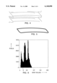
- FIG. 2 shows an image in the form of a first digital gray level image, of the drive or coast side tooth flanks, taken by one of the cameras in FIG. 1 and showing the contact patterns of the teeth of a ring gear of a pair of bevel gears to be tested, that have teeth curved in the lengthwise and profile directions,
- FIG. 3 shows a high-pass filtered version of the digital gray level image according to FIG. 1, in which gray value jumps such as those at the outlines of the tooth flanks are more heavily emphasized,
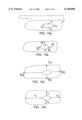
- FIG. 4 shows the gray level image according to FIG. 3 after processing with a threshold value and binarization of the individual pixels
- FIG. 5 shows the image of a tooth flank according to FIG. 4 after the flank outline has been closed by image processing
- FIG. 6 shows a histogram of the image according to FIG. 2,
- FIG. 7 represents an image matrix of the tooth flanks which contains the contact patterns as solid black areas and which is obtained by binary representation of the image according to FIG. 2,
- FIG. 8 shows an image of the tooth flank with a closed outline according to FIG. 5 and with a contact pattern according to FIG. 7 inscribed therein, after in version of the image matrix,
- FIG. 9 shows an equalized form of the representation according to FIG. 8,
- FIGS. 10a-10d show different steps of an embodiment of the evaluation of the image representation according to FIGS. 8 or 9, and
- FIG. 11 shows a flow chart for explaining the method and apparatus according to the invention.
- An embodiment of an apparatus for optoelectronically determining the contact patterns on tooth flanks of gears is generally numbered 20 in FIG. 1.
- a pair of bevel gears comprising a pinion 22 and a ring gear 24 is depicted as the gears to be tested.
- a paint spray system 26 serves to apply a marking compound to the tooth flanks of at least one gear of the pair of bevel gears to be tested, to make contact patterns 28 visible that come into being during operation.
- Two line-scan cameras 30 and 32 respectively are directed to the place at which the contact patterns on the tooth flanks of the ring gear 24 are visible.
- One line-scan camera serves to pick-up the drive side tooth flanks, and the other to pick-up the coast side tooth flanks of the marked ring gear 24.
- the line-scan camera 32 serves to pick-up gray level images. Its output is connected to an analog to digital or A/D converter 34 which is part of an image processing system generally numbered 36.
- the connection between the camera 32 and the A/D converter is comprised of a line 38 in the form of a signal cable, preferably a coaxial cable.
- the analog signals of the camera 32 that have been converted to digital signals by the A/D converter 34 are read into an image memory 40.
- the image memory 40 is connected via a bus 42 to a computer 44.
- a digital to analog or D/A converter 46 connected to the output of the A/D converter 34 is connected at its output to a monitor 48 for displaying the image picked-up by the camera.
- Means contained in the computer 44 for further processing a first digital image 50 supplied to the computer via the bus 42 from the image memory 40 will now be explained in detail on the basis of FIG. 11.
- a recursive high-pass filter 52 constitutes first means for processing the image matrix to generate a second digital image as shown in FIG. 3, in which the outline of each tooth flank is more heavily emphasized.
- the digital image supplied by the high-pass filter 52 is further processed in a histogram 54 which represents second means for processing the first digital image.
- the histogram representation 54 serves to determine a first threshold value 56 for all pixels and to subsequently binarize 58 the same.
- the binary image is subsequently processed with a search beam by a contour tracer 60 at block 58 to search for discontinuous outline regions and to interconnect them as shown in FIGS. 4 and 5.
- Further means 62 for forming another histogram representation 62 determine a second threshold value 64 to generate a digital image according to FIG.
- Means 68 are provided for superimposing (summing) the digital images supplied by the blocks 60 and 66, to determine for each tooth flank an analyzable digital image (FIG. 8) containing the outline, with the respective contact pattern inscribed therein. Subsequent to the superimposition (summation) an inversion of the image obtained by the superimposition from the images according to FIGS. 5 and 7 takes place in an inverter 70. The image can then be converted in an equalizer 72 to an equalized representation according to FIG. 9. Finally, the contact pattern determined according to FIG. 8 or FIG. 9 is evaluated in an analyzer 74.
- Digitization of the signals of the camera 32 Here, for example, 1024 pixels per line are stored line by line in an image matrix in the image memory 40. To each pixel is assigned a gray value between 0 (black) and 255 (white). This corresponds to an 8-bit digitization of the camera signal.
- the resulting first digital gray level image 50 is available for further processing in the image memory 40.
- the image includes the coast or drive side tooth flanks with the corresponding contact patterns of all teeth of the ring gear 24 of the pair of bevel gears to be tested.
- the 2-D high-pass filter 52 is applied to the first digital gray level image 50.
- the purpose of this high-pass filtering of the gray level image is to more heavily emphasize the flank boundaries, which are represented in the gray level image by jumps in the gray scale, as shown in FIG. 3.
- the contour regions are given higher gray values in the filtered image matrix, and thus they stand out as lighter image regions from the rest of the image.
- the gray value 255 is assigned to all pixels having a gray value below the threshold.
- the gray value 0 is assigned to all pixels having a gray value above the threshold value.
- the discontinuous regions of the outline are searched for and interconnected to form a closed contour by means of the contour tracer 60 with search beam. Pixels of lines that can not be extended to form closed contours are set at the gray value 255.
- two complete adjacent sides e.g. two adjacent facing sides or two sides adjacent at a corner of the outline
- four points of the outline can also be used for the further evaluation.
- a closed outline as shown in FIG. 5, facilitates the analysis.
- the closed outlines of all tooth flanks are available as an image matrix in the image memory 40.
- This image matrix is referred to here as the second digital image.
- the contact patterns 28 are extracted from the first digital gray level image.
- the contact patterns 28 are represented in the image matrix by pixels with a low gray value.
- the histogram 54 of the first digital gray level image 50 is evaluated (FIG. 6) to determine the range of gray values that can be assigned to the contact patterns.
- the histogram according to FIG. 6 shows the frequency of occurrence of the individual gray values in an image matrix.
- a suitable threshold value X e.g. 15% of the lowest gray values
- a binary representation (block 58 in FIG. 11) of the first digital gray level image is made on the basis of this threshold value. All pixels having a gray value less than the threshold value are assigned the gray value 0.
- the gray value 255 is assigned to all other pixels.
- a third digital image in the form of an image matrix containing the contact patterns as solid black areas (FIG. 7) in the region of the tooth flanks is now available in the image memory 54 as the result.
- flank regions represented in the second digital image (FIG. 5) by pixels having the gray value 255 and lying within the closed flank boundary contour are identified in the third digital image (FIG. 7).
- the gray values of these pixels in the third digital image are now inscribed into the respective positions in the image matrix of the second digital image (block 68 in FIG. 11). Subsequently the entire image matrix is inverted (block 70 in FIG. 11) to enable easier evaluation. Closed flank boundaries or outlines with the inscribed contact patterns (FIG. 8) are now available as the result.
- the image matrix can be additionally equalized. This corresponds to a development in a plane and is depicted in FIG. 9.
- the present image matrix according to FIGS. 8 or 9 can now be analyzed for the purpose aimed at here, namely the measurement of the position of the contact patterns relative to the outline or the flank boundaries.
- the image is analyzed in the following steps:
Landscapes
- Physics & Mathematics (AREA)
- General Physics & Mathematics (AREA)
- Engineering & Computer Science (AREA)
- Geometry (AREA)
- Computer Vision & Pattern Recognition (AREA)
- Theoretical Computer Science (AREA)
- Image Analysis (AREA)
- Length Measuring Devices By Optical Means (AREA)
Abstract
Description
Claims (25)
Applications Claiming Priority (2)
| Application Number | Priority Date | Filing Date | Title |
|---|---|---|---|
| DE19840969A DE19840969C2 (en) | 1998-09-08 | 1998-09-08 | Method and device for optoelectronic determination of the contact patterns on tooth flanks of gear wheels |
| DE19840969 | 1998-09-08 |
Publications (1)
| Publication Number | Publication Date |
|---|---|
| US6148098A true US6148098A (en) | 2000-11-14 |
Family
ID=7880212
Family Applications (1)
| Application Number | Title | Priority Date | Filing Date |
|---|---|---|---|
| US09/150,217 Expired - Fee Related US6148098A (en) | 1998-09-08 | 1998-09-09 | Method and apparatus for electro-optically determining the contact pattern on tooth flanks of gears |
Country Status (2)
| Country | Link |
|---|---|
| US (1) | US6148098A (en) |
| DE (1) | DE19840969C2 (en) |
Cited By (10)
| Publication number | Priority date | Publication date | Assignee | Title |
|---|---|---|---|---|
| US20060029257A1 (en) * | 2004-08-03 | 2006-02-09 | Honda Motor Co., Ltd. | Apparatus for determining a surface condition of an object |
| US20070058854A1 (en) * | 2005-09-14 | 2007-03-15 | Caskey Gregory T | Gear pattern inspection system |
| WO2008076060A1 (en) * | 2006-12-18 | 2008-06-26 | Scania Cv Ab (Publ) | Method and medium for generating contact pattern images, and vehicle |
| US20100158349A1 (en) * | 2008-12-23 | 2010-06-24 | General Electric Company | Method and system for estimating contact patterns |
| EP2330398B1 (en) * | 2009-12-01 | 2013-11-13 | Siemens Aktiengesellschaft | Method for inspecting a gear contact pattern of a gearbox in a steam turbine, and corresponding steam turbine system |
| US9029805B2 (en) | 2013-02-25 | 2015-05-12 | American Axle & Manufacturing, Inc. | Method for inspecting contact between mating gears |
| WO2016146276A1 (en) * | 2015-03-13 | 2016-09-22 | Bayerische Motoren Werke Aktiengesellschaft | Method and device for testing gearwheels |
| JP2017518510A (en) * | 2014-03-20 | 2017-07-06 | アレヴァ ヴィント ゲーエムベーハー | Test unit for quantitative analysis of contact pattern on tooth surface of gear, quantitative analysis method, and use of said test unit |
| WO2020113308A1 (en) * | 2018-12-05 | 2020-06-11 | Shumika Jason | Imaging system for assessing integrity of metal motive parts in industrial plants |
| CN114235719A (en) * | 2021-12-14 | 2022-03-25 | 西门子能源有限公司 | Measuring device and measuring method for contact coloring of end face teeth |
Families Citing this family (4)
| Publication number | Priority date | Publication date | Assignee | Title |
|---|---|---|---|---|
| DE102004001605A1 (en) * | 2004-01-09 | 2005-08-04 | Volkswagen Ag | Riveted joint testing method, especially for use in light metalworking processes, involved digital imaging of the joint and gray value quantification following by comparison with reference gray values |
| DE102009023722A1 (en) | 2009-06-03 | 2010-12-09 | Bayerische Motoren Werke Aktiengesellschaft | Method for determination and evaluation of contact pattern of teeth flank of gear wheel tooth, involves transforming color image in to binary image, and comparing binary image with reference criteria based on comparison criteria |
| DE102016218416B4 (en) | 2016-09-26 | 2024-01-04 | Bayerische Motoren Werke Aktiengesellschaft | Contact pattern testing machine paint application system, method for its operation and contact pattern testing machine |
| DE102017220127A1 (en) * | 2017-11-13 | 2019-05-16 | Zf Friedrichshafen Ag | Contact pattern test |
Citations (5)
| Publication number | Priority date | Publication date | Assignee | Title |
|---|---|---|---|---|
| EP0088879A1 (en) * | 1982-03-16 | 1983-09-21 | Werkzeugmaschinenfabrik Oerlikon-Bührle AG | Method of shaping the bearing surface of cycloidally curved tooth gears, and end milling cutter for carrying out this method |
| JPH03100434A (en) * | 1989-09-14 | 1991-04-25 | Nissan Motor Co Ltd | Method for deciding tooth contact quality of gear |
| US5287293A (en) * | 1990-12-31 | 1994-02-15 | Industrial Technology Research Institute | Method and apparatus for inspecting the contours of a gear |
| US5373735A (en) * | 1993-07-30 | 1994-12-20 | Gei Systems, Inc. | Gear testing method and apparatus for inspecting the contact area between mating gears |
| US5610994A (en) * | 1995-05-03 | 1997-03-11 | The Gleason Works | Digital imaging of tooth contact pattern |
-
1998
- 1998-09-08 DE DE19840969A patent/DE19840969C2/en not_active Expired - Fee Related
- 1998-09-09 US US09/150,217 patent/US6148098A/en not_active Expired - Fee Related
Patent Citations (5)
| Publication number | Priority date | Publication date | Assignee | Title |
|---|---|---|---|---|
| EP0088879A1 (en) * | 1982-03-16 | 1983-09-21 | Werkzeugmaschinenfabrik Oerlikon-Bührle AG | Method of shaping the bearing surface of cycloidally curved tooth gears, and end milling cutter for carrying out this method |
| JPH03100434A (en) * | 1989-09-14 | 1991-04-25 | Nissan Motor Co Ltd | Method for deciding tooth contact quality of gear |
| US5287293A (en) * | 1990-12-31 | 1994-02-15 | Industrial Technology Research Institute | Method and apparatus for inspecting the contours of a gear |
| US5373735A (en) * | 1993-07-30 | 1994-12-20 | Gei Systems, Inc. | Gear testing method and apparatus for inspecting the contact area between mating gears |
| US5610994A (en) * | 1995-05-03 | 1997-03-11 | The Gleason Works | Digital imaging of tooth contact pattern |
Cited By (15)
| Publication number | Priority date | Publication date | Assignee | Title |
|---|---|---|---|---|
| US20060029257A1 (en) * | 2004-08-03 | 2006-02-09 | Honda Motor Co., Ltd. | Apparatus for determining a surface condition of an object |
| US20070058854A1 (en) * | 2005-09-14 | 2007-03-15 | Caskey Gregory T | Gear pattern inspection system |
| WO2008076060A1 (en) * | 2006-12-18 | 2008-06-26 | Scania Cv Ab (Publ) | Method and medium for generating contact pattern images, and vehicle |
| US20100158349A1 (en) * | 2008-12-23 | 2010-06-24 | General Electric Company | Method and system for estimating contact patterns |
| WO2010074874A1 (en) * | 2008-12-23 | 2010-07-01 | General Electric Company | Method and system for estimating contact patterns |
| US8180143B2 (en) | 2008-12-23 | 2012-05-15 | General Electric Company | Method and system for estimating contact patterns |
| EP2330398B1 (en) * | 2009-12-01 | 2013-11-13 | Siemens Aktiengesellschaft | Method for inspecting a gear contact pattern of a gearbox in a steam turbine, and corresponding steam turbine system |
| US9029805B2 (en) | 2013-02-25 | 2015-05-12 | American Axle & Manufacturing, Inc. | Method for inspecting contact between mating gears |
| JP2017518510A (en) * | 2014-03-20 | 2017-07-06 | アレヴァ ヴィント ゲーエムベーハー | Test unit for quantitative analysis of contact pattern on tooth surface of gear, quantitative analysis method, and use of said test unit |
| WO2016146276A1 (en) * | 2015-03-13 | 2016-09-22 | Bayerische Motoren Werke Aktiengesellschaft | Method and device for testing gearwheels |
| CN107003207A (en) * | 2015-03-13 | 2017-08-01 | 宝马股份公司 | Method and apparatus for testing gears |
| US10371597B2 (en) | 2015-03-13 | 2019-08-06 | Bayerische Motoren Werke Aktiengesellschaft | Method and device for testing gearwheels |
| WO2020113308A1 (en) * | 2018-12-05 | 2020-06-11 | Shumika Jason | Imaging system for assessing integrity of metal motive parts in industrial plants |
| US11893726B2 (en) | 2018-12-05 | 2024-02-06 | Jason SHUMKA | Imaging system for assessing integrity of metal motive parts in industrial plants |
| CN114235719A (en) * | 2021-12-14 | 2022-03-25 | 西门子能源有限公司 | Measuring device and measuring method for contact coloring of end face teeth |
Also Published As
| Publication number | Publication date |
|---|---|
| DE19840969A1 (en) | 2000-03-23 |
| DE19840969C2 (en) | 2002-11-28 |
Similar Documents
| Publication | Publication Date | Title |
|---|---|---|
| US6148098A (en) | Method and apparatus for electro-optically determining the contact pattern on tooth flanks of gears | |
| JP4150390B2 (en) | Appearance inspection method and appearance inspection apparatus | |
| CN115482195B (en) | Train part deformation detection method based on three-dimensional point cloud | |
| KR960702360A (en) | ANGLE OF BEND DETECTOR AND STRAIGHT LINE EXTRACTOR USED THEREFOR, AND ANGLE OF BEND DETECTING POSITION SETTING APPARATUS | |
| KR20180115646A (en) | Bead recognition apparatus using vision camera and method thereof | |
| CN115330646B (en) | Metal component inspection method for fitness equipment paint spraying process | |
| CN110956624B (en) | Image definition evaluation method for three-dimensional object | |
| CN114280075A (en) | Online visual inspection system and method for surface defects of pipe parts | |
| CN113222955A (en) | Gear size parameter automatic measurement method based on machine vision | |
| DE69717603T2 (en) | METHOD AND APPARATUS FOR REDUCING UNWANTED NOISE EFFECTS IN A THREE-DIMENSIONAL COLOR IMAGE GENERATION SYSTEM | |
| CN117522944A (en) | Depth perception-based self-adaptive out-of-plane vibration measurement system and method | |
| JPH04346187A (en) | Quality decision method for subject to be detected | |
| CN115035175B (en) | Three-dimensional model construction data processing method and system | |
| JP4293653B2 (en) | Appearance inspection method | |
| DE10143522A1 (en) | Method and device for examining an object | |
| JP2508176B2 (en) | Automatic surface smoothness inspection device | |
| Sioma | Filtering algorithms for 3D range image analysis | |
| JPH10208046A (en) | X-ray foreign matter detection | |
| JPH05203584A (en) | Device for detecting characteristic amount on work surface | |
| JP2638121B2 (en) | Surface defect inspection equipment | |
| JP4220061B2 (en) | Periodic pattern defect inspection method and apparatus | |
| JPH0340813B2 (en) | ||
| EP0430246A2 (en) | Method and apparatus for evaluating color image signals | |
| US20220180504A1 (en) | Device for detecting a three-dimensional structure | |
| JP3509581B2 (en) | Appearance inspection method |
Legal Events
| Date | Code | Title | Description |
|---|---|---|---|
| FEPP | Fee payment procedure |
Free format text: PAYOR NUMBER ASSIGNED (ORIGINAL EVENT CODE: ASPN); ENTITY STATUS OF PATENT OWNER: LARGE ENTITY |
|
| FPAY | Fee payment |
Year of fee payment: 4 |
|
| AS | Assignment |
Owner name: KLINGELNBERG AG, SWITZERLAND Free format text: CHANGE OF NAME;ASSIGNOR:OERLIKON GEARTEC AG;REEL/FRAME:015065/0847 Effective date: 20040514 |
|
| FEPP | Fee payment procedure |
Free format text: PAYER NUMBER DE-ASSIGNED (ORIGINAL EVENT CODE: RMPN); ENTITY STATUS OF PATENT OWNER: LARGE ENTITY Free format text: PAYOR NUMBER ASSIGNED (ORIGINAL EVENT CODE: ASPN); ENTITY STATUS OF PATENT OWNER: LARGE ENTITY |
|
| FEPP | Fee payment procedure |
Free format text: PAT HOLDER NO LONGER CLAIMS SMALL ENTITY STATUS, ENTITY STATUS SET TO UNDISCOUNTED (ORIGINAL EVENT CODE: STOL); ENTITY STATUS OF PATENT OWNER: LARGE ENTITY |
|
| FEPP | Fee payment procedure |
Free format text: ENTITY STATUS SET TO UNDISCOUNTED (ORIGINAL EVENT CODE: BIG.); ENTITY STATUS OF PATENT OWNER: LARGE ENTITY |
|
| FPAY | Fee payment |
Year of fee payment: 8 |
|
| REMI | Maintenance fee reminder mailed | ||
| LAPS | Lapse for failure to pay maintenance fees | ||
| STCH | Information on status: patent discontinuation |
Free format text: PATENT EXPIRED DUE TO NONPAYMENT OF MAINTENANCE FEES UNDER 37 CFR 1.362 |
|
| FP | Lapsed due to failure to pay maintenance fee |
Effective date: 20121114 |