US6147444A - Lamp with reflector having specific neck portion - Google Patents
Lamp with reflector having specific neck portion Download PDFInfo
- Publication number
- US6147444A US6147444A US09/176,761 US17676198A US6147444A US 6147444 A US6147444 A US 6147444A US 17676198 A US17676198 A US 17676198A US 6147444 A US6147444 A US 6147444A
- Authority
- US
- United States
- Prior art keywords
- neck portion
- holes
- peen
- hole
- lamp
- Prior art date
- Legal status (The legal status is an assumption and is not a legal conclusion. Google has not performed a legal analysis and makes no representation as to the accuracy of the status listed.)
- Expired - Fee Related
Links
Images

Classifications
-
- H—ELECTRICITY
- H01—ELECTRIC ELEMENTS
- H01K—ELECTRIC INCANDESCENT LAMPS
- H01K1/00—Details
- H01K1/42—Means forming part of the lamp for the purpose of providing electrical connection, or support for, the lamp
Definitions
- the present invention relates to electric lamps.
- the present invention is particularly useful in connection with PAR lamps.
- an electric lamp which includes a reflector, a base such as a metal base shell attached to the reflector, and a light source positioned within the reflector and electrically connected to the base.
- a conventional PAR lamp includes a molded glass reflector having the general form of a dished portion leading to a neck portion which is formed around the axis of the reflector.
- at least two holes are formed in the neck portion to allow electrical connection to a light source positioned within the reflector.
- lead wires extend from a lamp positioned within the reflector. The lead wire extend through respective holes in the neck portion.
- Such lead wires are mechanically and electrically attached to a metal base shell which has been attached to the neck portion of the reflector.
- the base shell is a brass base shell which is threaded for screwing into a mating electrical socket in a conventional manner.
- the metal base shell When providing electric lamps of this type, it is essential that the metal base shell be firmly attached to the neck portion of the reflector. For example, when a completed lamp is placed in use it may be threaded into a socket with excessive vigor causing the threads of the lamp and the threads of the socket to bind. Further, during use the threaded base shell may be subjected to corrosion, dirt, temperature cycling and the like that may also act to bind the threads. In such instances, when it is necessary to replace the lamp, the bound threads will require an undesirably excessive unthreading force.
- a conventional PAR lamp is formed with two peen holes by pressing a glass gob between two mold faces.
- a glass gob is dropped into a female mold cavity, and a male mold face is pressed therein to form the reflector.
- Two slides each of which include a peen pin are brought in from opposite sides of the mold apparatus to plunge peen holes into the reflector neck portion.
- peen pins and therefore the peen holes are diametrically located.
- Respective portions of the metal base shell are then pressed into the peen holes provided in the neck portion of the reflector using a convectional peening tool.
- the neck portion is formed with a slope so as to be readily removable from the female mold. Due to a slight interference between the inside diameter of the metal base shell and the largest diameter of the neck portion of the glass reflector, the metal will be in tension when the base is pushed all the way down onto the neck portion. Such tension serves to hold the metal base shell in place during the peening operation.
- the metal base shell is not properly pushed very tightly all the way down against a seating ledge of the reflector, there will be a tendency for the metal base shell to move along the axis of the neck portion before and/or during the peening operation.
- the metal base shell and/or neck portion are not properly toleranced to provide the required metal tension, there may be a further tendency for the metal base shell to move along the axis of the neck portion.
- Such movement of the metal base shell will adversely affect the interface between the peens and the peen holes and provide an inadequate attachment between the metal base shell and neck portion. Further problems may result from the nature of the pressing operation.
- the peening operation provides a dilemma in that excessive pressing by the peening tool will fracture the glass reflector and possibly tear the metal of the metal base shell, and under pressing will prevent the peens from being sufficiently pressed into the peen holes to securely attach the metal base shell to the reflector.
- typically the two peen holes are positioned diametrically, and such configuration provides an axis for the peens and therefore the metal base shell to pivot about relative to the reflector. When this occurs, the remaining portion of the metal base shell can then swivel or lift from the outer peripheral surface of the neck portion of the reflector.
- this condition causes the peens to rock back and forth, thereby loosening the peens and/or causing them to rock out of the peen holes.
- This problem is compounded if the metal base shell is not properly seated and pressed squarely onto the neck portion since the metal base shell may be deformed during such inaccurate seating.
- the metal base shell will flex around the neck portion of the reflector, and an undesirably shorter peen may be formed by the peening tool. When the peening tool is removed, the metal base shell will tend to flex back thereby lifting the shorter peen(s) further away from and possibly out of the peen hole(s).
- rocking of the metal base shell may tend to round off the peens which will cause the peens to slip from the peen holes.
- the metal base shell will break free from the neck portion of the reflector.
- Another object of the present invention is to provide a lamp having a threaded metal base attached to a reflector which may be removed from a threaded electrical socket without causing the reflector to break free from the metal base.
- Yet another object of the present invention is to provide a lamp having a metal base which is firmly attached to a neck portion of a reflector.
- a further object of the present invention is to provide a lamp which may be removed from an electrical socket without concern for causing a hazardous condition due to separation of a metal base from a reflector.
- Another object of the present invention is to provide a lamp having a metal base attached to a neck portion of a reflector wherein there is no tendency for the base to pivot or otherwise move relative to the reflector.
- a further object is to provide an improved lamp wherein a metal base is attached to a neck portion of a reflector without the need for an adhesive.
- Yet a further object of the present invention is to provide a lamp having a metal base which is maintained squarely on a neck portion of a reflector.
- a further object of the present invention is to provide a lamp exhibiting a substantially reduced tendency for peens of a metal base to come out of respective peen holes in a neck portion of a reflector attached to the metal base.
- Another object of the present invention is to provide a lamp wherein the edge of the metal base adjacent the opening into which the neck portion of the reflector is inserted is not torn or otherwise damaged when the metal base is attached to the neck portion.
- Yet another object of the present invention is to provide a lamp wherein peens of a metal base inserted into peen holes of a neck portion of a reflector are not subjected to wear or bending.
- a further object of the present invention is to provide a lamp wherein a metal base is attached to a neck portion of a reflector using three or more peens, and which is not costly to produce.
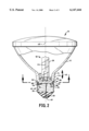
- FIG. 1 is a view of one embodiment of a lamp of the present invention
- FIG. 2 is a partial cross sectional view taken along lines 2--2 of FIG. 1 ;
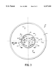
- FIG. 3 is a view taken along lines 3--3 of FIG. 2
- a lamp 10 comprises a reflector 12 having a neck portion 14 and a base 16 attached to the neck portion.
- base 16 is a threaded metal base shell.
- a light source 18 is positioned in the reflector 12 and electrically connected through the neck portion 14 to the metal base shell 16 in a conventional manner.
- two lead wires 20 and 22 are electrically and mechanically connected to a lamp filament 24 located within a lamp bulb 26. Lead wires 20 and 22 extend from the lamp bulb 26 and pass through respective apertures 28 and 30 at the base 32 of the neck portion 14.
- Distal end 34 of lead wire 20 is welded to an inner surface 36 of the metal base shell 16, and distal end 38 of lead wire 22 is welded to contact 40, in a conventional manner.
- the neck portion 14 is a molded extension of the reflector 12 and the metal base shell 16 is threaded at 42 in a conventional manner for insertion into a mating internally threaded lamp socket (not shown).
- the lamp 10 may be a PAR lamp.
- the neck portion 14 includes an outer peripheral surface 44 which generally extends in the direction 46 of a neck portion axis 48, which in the embodiment of FIG. 1 is also the axis of the lamp.
- the neck portion 14 is frusto conical as illustrated in FIGS. 1 and 2.
- the neck portion 14 includes at least two first holes extending from the outer peripheral surface 44 into the neck portion at a first region 50 of the neck portion. Such first holes are located one each on either side of a medial plane of the neck portion as described hereinafter.
- the neck portion 14 also includes at least one second hole extending from the outer peripheral surface into the neck portion at a second region 52 of the neck portion.
- first peen holes 54 and 56 at region 50 and two second peen holes 58 and 60 at region 52 are two first peen holes 54 and 56 at region 50 and two second peen holes 58 and 60 at region 52.
- a medial plane which extends perpendicular to the drawing sheet and through axis 48 is represented by line 62.
- a first hole 54 and an opposite second hole 58 are located on one side 64 of the medial plane 62
- a first hole 56 and an opposite second hole 60 are located on an opposite side 66 of the medial plane 62.
- each first hole extends into the neck portion in a direction other than radially towards the axis 48.
- each second hole also extends into the neck portion in a direction other than radially towards the axis 48.
- each first peen hole 54 and 56 extends in the direction 68 of respective hole axes 70 and 72.
- each second peen hole 58 and 60 extends in the direction 68 of respective hole axes 74 and 76.
- Axes 70, 72, 74 and 76 are parallel to the medial plane 62. In the embodiment of FIGS.
- axes 70 and 74 are linearly aligned chordally across the circumference of the neck portion 14.
- axes 72 and 76 are linearly aligned chordally across the circumference of the neck portion 14.
- first and second holes are provided which extend into the neck portion 14 in a direction other than radially towards the axis 48. It will be readily recognized by someone having ordinary skill in the art that one or more of axes 70, 72, 74 and 76 may be oriented in some other direction relative to medial plane 62 so long as axes 70 and 72 are not oriented radially towards axis 48.
- the first and second holes may be located approximately equiangularly relative to the neck portion axis.
- the holes 54, 56, 58 and 60 are approximately equally spaced around the outer peripheral surface 44, the holes being spaced at 78 about 90° (illustrated for clarity only between adjacent holes 54 and 58).
- the metal base shell 16 is attached to the neck portion 14 of the reflector 12 by inserting the neck portion into the open end of the metal base shell so that the metal base shell overlaps the first and second holes which extend into the peripheral surface 44.
- a first end 80 of the cylindrical neck portion 14 is inserted into a cylindrical open end 82 of the metal base shell 16 until the end 82 engages an abutment surface or ledge 84 of the reflector 12.
- Abutment surface 84 extends radially relative to axis 48 at an opposite second end 86 of the neck portion.
- the metal base 16 completely overlaps the first holes 54, 56 and the opposite second holes 58, 60.
- Attachment of the metal base 16 to the neck portion 14 is effected by providing base portions such as peens 88, 90, 92 and 94 of the metal base 16 which extend into holes 54, 56, 58 and 60, respectively.
- end 82 of the metal base 16 is adjacent the first holes 54, 56 and second holes 58, 60, and base portions 88, 90, 92 and 94 are structured and arranged so as to be offset from, and therefore not to overlap, the end 82.
- the base portions 88, 90, 92 and 94 extend in the direction of respective axes 96, 98, 100 and 102 which extend radially towards the first axis 48.
- the neck portion of the reflector has four peen holes the axis of each of which extends in a direction other than radially towards the axis of the neck portion, it is possible to provide a lamp wherein there is substantially no tendency for the metal base shell of the lamp to pivot or rock relative to the reflector as there is no common pivot axis.
- at least the two first peen holes are disposed off of the neck portion axis or centerline thereby substantially eliminating any rocking condition.
- Such prevention of pivoting or rocking substantially reduces the tendency for the peens of the metal base to come out of respective peen holes or to become worn or bent and thereby reduces the tendency for the metal base to become unattached from the reflector.
- any rotational movement of the metal base shell relative to the neck portion of the reflector will be prevented by any two of the peens extending into respective peen holes.
- the need for interference between the neck portion of the reflector and the inner diameter of the metal base shell is diminished. This feature allows more forgiveness for the natural variations in pressed glass.
- the metal base shell may be attached to and maintained squarely on the neck portion of the reflector without an adhesive. Further, by increasing the number of peens and peen holes it is possible to slightly decrease their size which permits positioning of the peens and peen holes further from the seating plane of the metal base shell. For example, by providing four peens and four peen holes as illustrated in FIGS.
- the foregoing features provide an improved lamp having, for example, a threaded metal base firmly attached to a reflector, which may be removed from a mating threaded electrical socket without causing the reflector to break free from the metal base. Such a lamp eliminates concern of creating a hazardous condition due to separation of the metal base and reflector.
- the lamp of the present invention may be fabricated without major modification of existing equipment.
- molding equipment which presently includes two slides each having a single peen pin which is moved radially towards the neck portion axis to form one of the peen holes of the two diametrical peen holes in the neck portion, may be readily modified.
- one or both of the conventional diametrically disposed single peen pins may each be replaced with a pair of peen pins, each such pair including two off radius peen pins which are on opposite sides and are equidistant from and parallel to the medial plane of the neck portion.
- Such an apparatus will produce the lamp illustrated in FIGS. 1 to 3.
Landscapes
- Non-Portable Lighting Devices Or Systems Thereof (AREA)
Priority Applications (4)
| Application Number | Priority Date | Filing Date | Title |
|---|---|---|---|
| US09/176,761 US6147444A (en) | 1998-10-22 | 1998-10-22 | Lamp with reflector having specific neck portion |
| CA002281397A CA2281397A1 (en) | 1998-10-22 | 1999-09-02 | Lamp |
| EP99120612A EP1005062A3 (de) | 1998-10-22 | 1999-10-18 | Lampe |
| CN99123332.8A CN1107201C (zh) | 1998-10-22 | 1999-10-22 | 灯 |
Applications Claiming Priority (1)
| Application Number | Priority Date | Filing Date | Title |
|---|---|---|---|
| US09/176,761 US6147444A (en) | 1998-10-22 | 1998-10-22 | Lamp with reflector having specific neck portion |
Publications (1)
| Publication Number | Publication Date |
|---|---|
| US6147444A true US6147444A (en) | 2000-11-14 |
Family
ID=22645715
Family Applications (1)
| Application Number | Title | Priority Date | Filing Date |
|---|---|---|---|
| US09/176,761 Expired - Fee Related US6147444A (en) | 1998-10-22 | 1998-10-22 | Lamp with reflector having specific neck portion |
Country Status (4)
| Country | Link |
|---|---|
| US (1) | US6147444A (de) |
| EP (1) | EP1005062A3 (de) |
| CN (1) | CN1107201C (de) |
| CA (1) | CA2281397A1 (de) |
Cited By (6)
| Publication number | Priority date | Publication date | Assignee | Title |
|---|---|---|---|---|
| US6525454B2 (en) * | 2000-03-22 | 2003-02-25 | Koninklijke Philips Electronics N.V. | Electric lamp |
| US6600256B2 (en) * | 2000-03-22 | 2003-07-29 | Koninklijke Philips Electronics N.V. | Electric lamp |
| US6657369B1 (en) * | 1998-11-18 | 2003-12-02 | Matsushita Electric Industrial Co., Ltd. | Lamp with reflector and method of manufacturing the same |
| US20050112982A1 (en) * | 2003-11-24 | 2005-05-26 | Rense Mark S. | Assembly for precision focus of compact par lamps |
| US20070008728A1 (en) * | 2004-09-27 | 2007-01-11 | Regal King Comercial Offshore De Macau Limitada | Lamp with spot light and flood light features |
| US20070159825A1 (en) * | 2006-01-06 | 2007-07-12 | Ham In S | Photocatalytic apparatus |
Citations (6)
| Publication number | Priority date | Publication date | Assignee | Title |
|---|---|---|---|---|
| DE2938189A1 (de) * | 1979-09-21 | 1981-03-26 | Patent-Treuhand-Gesellschaft für elektrische Glühlampen mbH, 81543 München | Gluehlampe |
| GB2064747A (en) * | 1979-12-04 | 1981-06-17 | Cibie Projecteurs | Device for securing a bulb to the reflector of a headlamp |
| US4342142A (en) * | 1979-09-17 | 1982-08-03 | Tokyo Shibaura Denki Kabushiki Kaisha | Method for manufacturing sealed-beam type electric bulb |
| EP0100294A2 (de) * | 1982-07-30 | 1984-02-08 | Collins Dynamics | Leuchte mit einer Fassung für mehrere Glühlampen |
| US4816977A (en) * | 1988-02-16 | 1989-03-28 | Rcs Industries, Inc. | Lamp with removable bulb capsule |
| EP0516231A2 (de) * | 1991-05-31 | 1992-12-02 | Koninklijke Philips Electronics N.V. | Elektrische Reflektorlampe |
-
1998
- 1998-10-22 US US09/176,761 patent/US6147444A/en not_active Expired - Fee Related
-
1999
- 1999-09-02 CA CA002281397A patent/CA2281397A1/en not_active Abandoned
- 1999-10-18 EP EP99120612A patent/EP1005062A3/de not_active Withdrawn
- 1999-10-22 CN CN99123332.8A patent/CN1107201C/zh not_active Expired - Fee Related
Patent Citations (6)
| Publication number | Priority date | Publication date | Assignee | Title |
|---|---|---|---|---|
| US4342142A (en) * | 1979-09-17 | 1982-08-03 | Tokyo Shibaura Denki Kabushiki Kaisha | Method for manufacturing sealed-beam type electric bulb |
| DE2938189A1 (de) * | 1979-09-21 | 1981-03-26 | Patent-Treuhand-Gesellschaft für elektrische Glühlampen mbH, 81543 München | Gluehlampe |
| GB2064747A (en) * | 1979-12-04 | 1981-06-17 | Cibie Projecteurs | Device for securing a bulb to the reflector of a headlamp |
| EP0100294A2 (de) * | 1982-07-30 | 1984-02-08 | Collins Dynamics | Leuchte mit einer Fassung für mehrere Glühlampen |
| US4816977A (en) * | 1988-02-16 | 1989-03-28 | Rcs Industries, Inc. | Lamp with removable bulb capsule |
| EP0516231A2 (de) * | 1991-05-31 | 1992-12-02 | Koninklijke Philips Electronics N.V. | Elektrische Reflektorlampe |
Cited By (8)
| Publication number | Priority date | Publication date | Assignee | Title |
|---|---|---|---|---|
| US6657369B1 (en) * | 1998-11-18 | 2003-12-02 | Matsushita Electric Industrial Co., Ltd. | Lamp with reflector and method of manufacturing the same |
| US6525454B2 (en) * | 2000-03-22 | 2003-02-25 | Koninklijke Philips Electronics N.V. | Electric lamp |
| US6600256B2 (en) * | 2000-03-22 | 2003-07-29 | Koninklijke Philips Electronics N.V. | Electric lamp |
| US20050112982A1 (en) * | 2003-11-24 | 2005-05-26 | Rense Mark S. | Assembly for precision focus of compact par lamps |
| US7227308B2 (en) | 2003-11-24 | 2007-06-05 | General Electric Company | Assembly for precision focus of compact PAR lamps |
| US20070008728A1 (en) * | 2004-09-27 | 2007-01-11 | Regal King Comercial Offshore De Macau Limitada | Lamp with spot light and flood light features |
| US7938564B2 (en) | 2004-09-27 | 2011-05-10 | Gardenia Industrial Limited | Lamp with spot light and flood light features |
| US20070159825A1 (en) * | 2006-01-06 | 2007-07-12 | Ham In S | Photocatalytic apparatus |
Also Published As
| Publication number | Publication date |
|---|---|
| CN1252508A (zh) | 2000-05-10 |
| CN1107201C (zh) | 2003-04-30 |
| CA2281397A1 (en) | 2000-04-22 |
| EP1005062A2 (de) | 2000-05-31 |
| EP1005062A3 (de) | 2000-06-14 |
Similar Documents
| Publication | Publication Date | Title |
|---|---|---|
| JP3283870B2 (ja) | ハロゲンランプ | |
| EP0698902B1 (de) | Sperrbügel für Lampensockel | |
| US6147444A (en) | Lamp with reflector having specific neck portion | |
| US4496874A (en) | Electric lamp having a mechanically connected lamp cap | |
| US5436526A (en) | Method of placing a single-capped electric lamp in a lampholder, single-capped electric lamp designed for this purpose, and luminaire provided with the single-capped electric lamp | |
| US4611093A (en) | Electrical bushing having a replaceable stud | |
| US6252170B1 (en) | Twist-on wire connector with torque limiting mechanism | |
| US4922388A (en) | Vehicle headlight | |
| US4782197A (en) | Electrical bushing having a replaceable stud | |
| US5381070A (en) | Lamp base locking clip | |
| US5823829A (en) | Connection body's fitting connection structures and sockets structures to hold an electric bulb | |
| US9876326B1 (en) | Universal lightbulb socket | |
| EP0856867A2 (de) | Öse für Lampe | |
| JP2003123503A (ja) | 反射器ランプ | |
| US4003624A (en) | Snag-proof electric lamp base having a single end-contact component | |
| EP1031164B1 (de) | Elektrische lampe mit einem vergleichweise robusten lampensockel | |
| EP0637100A1 (de) | Montage oder verbindungsstruktur eines verbinders und struktur zur befestigung einer lampe auf einem sockel | |
| CN107830495B (zh) | 一种车用信号灯安装结构及其安装方法 | |
| US5893769A (en) | Bulb socket with fastening structure for electric connectors | |
| JP7517646B2 (ja) | 揺動連結具の製造方法 | |
| US20030228801A1 (en) | Low profile lamp socket | |
| KR200227771Y1 (ko) | 전구 소켓 | |
| CN1599942A (zh) | 电灯泡 | |
| US825228A (en) | Adapter for lamp-sockets. | |
| EP2980828B1 (de) | Verbesserte lampenanordnung |
Legal Events
| Date | Code | Title | Description |
|---|---|---|---|
| AS | Assignment |
Owner name: OSRAM SYLVANIA INC., MASSACHUSETTS Free format text: ASSIGNMENT OF ASSIGNORS INTEREST;ASSIGNORS:GALLANT, JOSEPH P.;GAGNON, SANDRA M., ADMINISTRATRIX FOR PETER R. GAGNON (DECEASED);REEL/FRAME:009653/0462 Effective date: 19981204 |
|
| REMI | Maintenance fee reminder mailed | ||
| LAPS | Lapse for failure to pay maintenance fees | ||
| STCH | Information on status: patent discontinuation |
Free format text: PATENT EXPIRED DUE TO NONPAYMENT OF MAINTENANCE FEES UNDER 37 CFR 1.362 |
|
| FP | Lapsed due to failure to pay maintenance fee |
Effective date: 20041114 |