US6147431A - Stator core and method of manufacture therefor - Google Patents
Stator core and method of manufacture therefor Download PDFInfo
- Publication number
- US6147431A US6147431A US09/141,327 US14132798A US6147431A US 6147431 A US6147431 A US 6147431A US 14132798 A US14132798 A US 14132798A US 6147431 A US6147431 A US 6147431A
- Authority
- US
- United States
- Prior art keywords
- strips
- stator core
- strip
- stacked
- sheet steel
- Prior art date
- Legal status (The legal status is an assumption and is not a legal conclusion. Google has not performed a legal analysis and makes no representation as to the accuracy of the status listed.)
- Expired - Lifetime
Links
Images


Classifications
-
- H—ELECTRICITY
- H02—GENERATION; CONVERSION OR DISTRIBUTION OF ELECTRIC POWER
- H02K—DYNAMO-ELECTRIC MACHINES
- H02K15/00—Processes or apparatus specially adapted for manufacturing, assembling, maintaining or repairing of dynamo-electric machines
- H02K15/02—Processes or apparatus specially adapted for manufacturing, assembling, maintaining or repairing of dynamo-electric machines of stator or rotor bodies
- H02K15/021—Magnetic cores
- H02K15/026—Wound cores
-
- H—ELECTRICITY
- H02—GENERATION; CONVERSION OR DISTRIBUTION OF ELECTRIC POWER
- H02K—DYNAMO-ELECTRIC MACHINES
- H02K1/00—Details of the magnetic circuit
- H02K1/06—Details of the magnetic circuit characterised by the shape, form or construction
- H02K1/12—Stationary parts of the magnetic circuit
- H02K1/16—Stator cores with slots for windings
-
- H—ELECTRICITY
- H02—GENERATION; CONVERSION OR DISTRIBUTION OF ELECTRIC POWER
- H02K—DYNAMO-ELECTRIC MACHINES
- H02K2201/00—Specific aspects not provided for in the other groups of this subclass relating to the magnetic circuits
- H02K2201/09—Magnetic cores comprising laminations characterised by being fastened by caulking
-
- Y—GENERAL TAGGING OF NEW TECHNOLOGICAL DEVELOPMENTS; GENERAL TAGGING OF CROSS-SECTIONAL TECHNOLOGIES SPANNING OVER SEVERAL SECTIONS OF THE IPC; TECHNICAL SUBJECTS COVERED BY FORMER USPC CROSS-REFERENCE ART COLLECTIONS [XRACs] AND DIGESTS
- Y10—TECHNICAL SUBJECTS COVERED BY FORMER USPC
- Y10T—TECHNICAL SUBJECTS COVERED BY FORMER US CLASSIFICATION
- Y10T29/00—Metal working
- Y10T29/49—Method of mechanical manufacture
- Y10T29/49002—Electrical device making
- Y10T29/49009—Dynamoelectric machine
- Y10T29/49011—Commutator or slip ring assembly
-
- Y—GENERAL TAGGING OF NEW TECHNOLOGICAL DEVELOPMENTS; GENERAL TAGGING OF CROSS-SECTIONAL TECHNOLOGIES SPANNING OVER SEVERAL SECTIONS OF THE IPC; TECHNICAL SUBJECTS COVERED BY FORMER USPC CROSS-REFERENCE ART COLLECTIONS [XRACs] AND DIGESTS
- Y10—TECHNICAL SUBJECTS COVERED BY FORMER USPC
- Y10T—TECHNICAL SUBJECTS COVERED BY FORMER US CLASSIFICATION
- Y10T29/00—Metal working
- Y10T29/49—Method of mechanical manufacture
- Y10T29/49002—Electrical device making
- Y10T29/49009—Dynamoelectric machine
- Y10T29/49012—Rotor
-
- Y—GENERAL TAGGING OF NEW TECHNOLOGICAL DEVELOPMENTS; GENERAL TAGGING OF CROSS-SECTIONAL TECHNOLOGIES SPANNING OVER SEVERAL SECTIONS OF THE IPC; TECHNICAL SUBJECTS COVERED BY FORMER USPC CROSS-REFERENCE ART COLLECTIONS [XRACs] AND DIGESTS
- Y10—TECHNICAL SUBJECTS COVERED BY FORMER USPC
- Y10T—TECHNICAL SUBJECTS COVERED BY FORMER US CLASSIFICATION
- Y10T29/00—Metal working
- Y10T29/49—Method of mechanical manufacture
- Y10T29/49002—Electrical device making
- Y10T29/4902—Electromagnet, transformer or inductor
- Y10T29/49071—Electromagnet, transformer or inductor by winding or coiling
-
- Y—GENERAL TAGGING OF NEW TECHNOLOGICAL DEVELOPMENTS; GENERAL TAGGING OF CROSS-SECTIONAL TECHNOLOGIES SPANNING OVER SEVERAL SECTIONS OF THE IPC; TECHNICAL SUBJECTS COVERED BY FORMER USPC CROSS-REFERENCE ART COLLECTIONS [XRACs] AND DIGESTS
- Y10—TECHNICAL SUBJECTS COVERED BY FORMER USPC
- Y10T—TECHNICAL SUBJECTS COVERED BY FORMER US CLASSIFICATION
- Y10T29/00—Metal working
- Y10T29/49—Method of mechanical manufacture
- Y10T29/49002—Electrical device making
- Y10T29/4902—Electromagnet, transformer or inductor
- Y10T29/49073—Electromagnet, transformer or inductor by assembling coil and core
-
- Y—GENERAL TAGGING OF NEW TECHNOLOGICAL DEVELOPMENTS; GENERAL TAGGING OF CROSS-SECTIONAL TECHNOLOGIES SPANNING OVER SEVERAL SECTIONS OF THE IPC; TECHNICAL SUBJECTS COVERED BY FORMER USPC CROSS-REFERENCE ART COLLECTIONS [XRACs] AND DIGESTS
- Y10—TECHNICAL SUBJECTS COVERED BY FORMER USPC
- Y10T—TECHNICAL SUBJECTS COVERED BY FORMER US CLASSIFICATION
- Y10T29/00—Metal working
- Y10T29/49—Method of mechanical manufacture
- Y10T29/49002—Electrical device making
- Y10T29/4902—Electromagnet, transformer or inductor
- Y10T29/49075—Electromagnet, transformer or inductor including permanent magnet or core
- Y10T29/49078—Laminated
-
- Y—GENERAL TAGGING OF NEW TECHNOLOGICAL DEVELOPMENTS; GENERAL TAGGING OF CROSS-SECTIONAL TECHNOLOGIES SPANNING OVER SEVERAL SECTIONS OF THE IPC; TECHNICAL SUBJECTS COVERED BY FORMER USPC CROSS-REFERENCE ART COLLECTIONS [XRACs] AND DIGESTS
- Y10—TECHNICAL SUBJECTS COVERED BY FORMER USPC
- Y10T—TECHNICAL SUBJECTS COVERED BY FORMER US CLASSIFICATION
- Y10T29/00—Metal working
- Y10T29/53—Means to assemble or disassemble
- Y10T29/5313—Means to assemble electrical device
- Y10T29/53143—Motor or generator
- Y10T29/53161—Motor or generator including deforming means
Definitions
- This invention relates to a stator core which can be used in a stator in an automobile alternator, for example, and a method of manufacture therefor.
- FIG. 7 is a perspective view showing a stator core used in the stator of a conventional automobile alternator.
- This stator core 1 is composed of a single strip 2 made of sheet steel formed with tooth portions 2a and core back portions 2b, wound spirally such that the tooth portions 2a stack up in line with each other and the core back portions 2b stack up in line with each other, and the core 1 is arc welded on its outer surface so that the spirally wound strip is integrated. Furthermore, the welded portions 3 are disposed circumferentially at a prescribed pitch and further across the entire area in the direction of lamination on the outer surface of the wound strip 2.
- each strip 2 is wound around an internal diameter guide cylinder 5 from its leading end and moves downwards as the winding proceeds so that it forms a lamination.
- the wound strip 2 is formed to an internal diameter corresponding to the external diameter of the internal diameter guide cylinder 5.
- the external diameter of the wound strip 2 is controlled by an external diameter guide cylinder 6.
- the strip 2 is wound spirally under the control of the internal diameter guide cylinder 5 and the external diameter guide cylinder 6 until the lamination reaches a certain height (thickness) and is then cut.
- the wound strip 2 is then removed and its outer surface is arc welded to obtain a stator core 1.
- the conventional method of manufacture for a stator core aims to cut costs by making use of the protrusions and recesses in the tooth portions 2a, punching two strips 2 with intermeshed protrusions and recesses from a single long band of sheet steel 4, so that two stator cores 1 can be manufactured from sheet steel 4 having the length necessary for one stator core 1.
- stator core 1 is manufactured by winding a single strip 2, and so if the height of the stator core 1 is increased to raise output, or the sheet is made thinner to reduce core loss, the time required to wind the strip 2 increases and production costs increase.
- An object of the present invention is to overcome the problem mentioned above by providing a stator core in which winding time can be reduced without loss of performance by integrating and winding a plurality of strips, and a method of manufacture therefor.
- a stator core according to the present invention is composed of a plurality of strips made of sheet steel formed with tooth portions and core back portions, wherein the plurality of strips are stacked such that the tooth portions line up together and the core back portions line up together, and wound spirally.
- a method of manufacture for a stator core is provided with a punching process in which strips having tooth portions and core back portions are punched from a long band of sheet steel, a stacking process in which a plurality of the strips are stacked such that the tooth portions line up together and the core back portions line up together and the stacked plurality of strips are integrated to form a strip lamination, and a winding process in which the strip lamination is wound spirally and the wound strip lamination is integrated.
- a method of manufacture for a stator core according to the present invention may be provided with a punching process in which strip laminations having tooth portions and core back portions are punched from a stacked plurality of long bands of sheet steel, and a winding process in which the strip laminations are wound spirally and the wound strip laminations are integrated.
- FIG. 1 is a plan view explaining the process of punching sheet steel in the method of manufacture for a stator core according to Embodiment 1 of the present invention
- FIG. 2 is a perspective view explaining the process of stacking strips in the method of manufacture for a stator core according to Embodiment 1 of the present invention
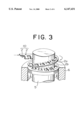
- FIG. 3 is a perspective view explaining the process of winding strips in the method of manufacture for a stator core according to Embodiment 1 of the present invention
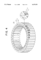
- FIG. 4 is a perspective view showing a stator core manufactured by the method of manufacture for a stator core according to Embodiment 1 of the present invention
- FIG. 5 is a plan view explaining a process of punching sheet steel in the method of manufacture for a stator core according to Embodiment 2 of the present invention
- FIG. 6 is a plan view explaining a process of punching sheet steel in the method of manufacture for a stator core according to Embodiment 3 of the present invention.
- FIG. 7 is a perspective view showing a conventional stator core
- FIG. 8 is a plan view explaining the process of punching sheet steel in a conventional method of manufacture for a stator core.
- FIG. 9 is a perspective view explaining the process of winding strips in a conventional method of manufacture for a stator core.
- FIG. 1 is a plan view explaining the process of punching sheet steel in the method of manufacture for a stator core according to Embodiment 1 of the present invention
- FIG. 2 is a perspective view explaining the process of stacking strips in the method of manufacture for a stator core according to Embodiment 1 of the present invention
- FIG. 3 is a perspective view explaining the process of winding strips in the method of manufacture for a stator core according to Embodiment 1 of the present invention
- FIG. 4 is a perspective view showing a stator core manufactured by the method of manufacture for a stator core according to Embodiment 1 of the present invention.
- 1 mm thick, 22 mm wide sheet steel 4 is fed to a press (not shown), which forms the single band of sheet steel 4 into two strips 2 having tooth portions 2a, core back portions 2b, and notches 2c formed at a position of the core back portion opposite to each of the tooth portions 2c as shown in FIG. 1.
- the two strips 2 are separated and the strips are turned over and stacked up so that their tooth portions 2a line up together and their core back portions 2b line up together and notches 2c line up together.
- the two stacked strips 2 are welded to make a strip lamination 10. The two strips are welded along an edge at weld portions 9 to integrate them.
- FIG. 1 mm thick, 22 mm wide sheet steel 4 is fed to a press (not shown), which forms the single band of sheet steel 4 into two strips 2 having tooth portions 2a, core back portions 2b, and notches 2c formed at a position of the core back portion opposite to each of the tooth portions 2c as shown in FIG. 1.
- the two strips 2 are separated and the strips
- the strip lamination 10 is wound around an internal diameter guide cylinder 5 from its leading end and moves downwards as the winding proceeds so that it forms a lamination. At this time, the wound strip lamination 10 is formed to an internal diameter corresponding to the external diameter of the internal diameter guide cylinder 5. Also, the external diameter of the wound strip lamination 10 is controlled by an external diameter guide cylinder 6.
- the strip lamination 10 is wound spirally under the control of the internal diameter guide cylinder 5 and the external diameter guide cylinder 6 until the lamination reaches a certain height (thickness) and is then cut.
- the wound strip lamination 10 is integrated by applying pressure to it from above and below and caulking it, and then it is removed from the winding device to obtain a stator core 20.
- two strips 2 are punch formed from a single long band of sheet steel 4, the two strips 2 are stacked and integrated to form a single strip lamination 10, and the single strip lamination 10 is wound up to produce a stator core 20, and so winding time can be reduced without loss of performance, and the stator core can be produced at reduced cost.
- the conventional method of manufacture requires that the strip 2 be wound 27 times, but because the strip lamination 10 in Embodiment 1 is composed of two stacked strips 2, only about 14 turns are required, which is roughly half the number of turns. So, if the winding speed is the same, the winding time is halved and costs can be reduced. Furthermore, since the thickness of each of the strips 2 being wound in Embodiment 1 is the same as that of the strip in the conventional method of manufacture, the same performance can be attained as in the conventional method of manufacture.
- Embodiment 1 enables output to be increased during power generation without requiring any more winding time than that required conventionally.
- burring no longer interferes when the strip laminate 10 is wound, and so unwanted gaps do not form between the strip laminate 10 and misalignment of tooth portions 2a and core back portions 2b is reduced when the strip laminate 10 is wound.
- the stator core 20 is composed by winding two integrated strips 2, the number of turns required to wind the strips 2 is reduced, enabling a stator core to be obtained more cheaply.
- the two strips 2 are described as being integrated by welding, but the method of integration of the two strips 2 is not limited to welding and may be, for example, caulking.
- the wound strip lamination 10 is described as being integrated by applying pressure to it from above and below and caulking it, but the method of integration of the wound strip lamination 10 is not limited to caulking and may be, for example, welding.
- the two strips 2 are described as being formed from a single band of sheet steel 4 such that the protrusions and recesses of their respective tooth portions 2a are intermeshed, but the two strips 2 may be formed side by side over the width of a single band of sheet steel 4 such that their tooth portions 2a point in the same direction.
- the disadvantage is that the yield drops, but then it is not necessary turn the two strips 2 over to stack them, and so the stacking operation can be improved significantly.
- Embodiment 2 1 mm thick, 44 mm wide sheet steel 4A is fed to a press and, as shown in FIG. 5, the band of sheet steel 4A is formed by the press into four strips 2A, 2B, 2C, 2D having tooth portions 2a and core back portions 2b. Next, the four strips 2A, 2B, 2C, 2D are separated and two strips 2A, 2C are stacked and integrated to make a strip lamination 10 and two strips 2B, 2D are stacked and integrated to make another strip lamination 10. The rest of the construction has the same composition as Embodiment 1 above.
- Embodiment 2 four strips 2A, 2B, 2C, 2D are punched from a single band of sheet steel 4A, and strips 2A, 2C (2B, 2D), whose tooth portions point in the same direction, are stacked together.
- the direction of the burring in the two stacked strips 2A, 2C (2B, 2D) is the same, and so the burring on each of the two strips 2A, 2C (2B, 2D) does not interfere with that on the other when they are stacked and no unwanted gaps occur between the strips 2A, 2C (2B, 2D).
- Embodiment 2 the troublesome stacking operation of Embodiment 1, in which the two punched strips 2 must be turned over so that the burring on each faces in the same direction, is not required during stacking of two strips, and handling is made that much easier and costs can be reduced.
- Embodiment 3 two bands of 1 mm thick, 22 mm wide sheet steel 4 are stacked and integrated by welding, then fed to a press and, as shown in FIG. 6, the two bands of sheet steel 4 are formed by the press into two strip laminations 10 having tooth portions 2a and core back portions 2b. Each of the strip laminations 10 thus formed is then fed to a winding process.
- the rest of the construction has the same composition as Embodiment 1 above.
- strip laminations 10 can be formed from two stacked and integrated strips 2 during the punching process, so that the troublesome stacking operation, in which two punched strips 2 must be stacked with their tooth portions 2a and core back portions 2b aligned and integrated, is not required and costs can be reduced considerably.
- the two bands of sheet steel 4 are described as being fed to the press after being stacked and integrated by welding, but the two bands of sheet steel 4 may be stacked and fed to the press and integrated by caulking the two bands of sheet steel 4 when the tooth portions 2a and core back portions 2b are punched. Also, two presses may be disposed in series so that the punching process for the tooth portions 2a and core back portions 2b and the caulking process can be carried out in quick succession.
- a plurality of strips made of sheet steel formed with tooth portions and core back portions are stacked such that the tooth portions line up together and the core back portions line up together and are wound spirally, and so strip winding time can be reduced and a cheap stator core can be obtained without loss of performance.
- the present invention is provided with a punching process in which strips formed with tooth portions and core back portions are punched from a long band of sheet steel, a stacking process in which a plurality of the strips are stacked such that the tooth portions line up together and the core back portions line up together and the stacked plurality of strips are integrated to form strip laminations, and a winding process in which the strip lamination is wound spirally and the wound strip lamination is integrated, and so winding time is reduced and a stator core can be manufactured at low cost without loss of performance.
- a plurality of strips formed with tooth portions and core back portions may be punched from a single long band of sheet steel, and in the stacking process, strips with their tooth portions pointing in the same direction may be stacked together and integrated to form strip laminations, and so the burring on each of the stacked plurality of strips faces in the same direction, the stacking operation is facilitated, and the formation of unwanted gaps between the strips is also prevented.
- At least one pair of strips may be punched over the width of the sheet steel such that two of the strips form a pair by intermeshing the protrusions and recesses of their respective tooth portions, and so the yield can be improved.
- the present invention may be provided with a punching process in which strip laminations having tooth portions and core back portions are punched from a stacked plurality of long bands of sheet steel, and a winding process in which the strip laminations are wound spirally and the wound strip laminations are integrated, and so the strip winding process becomes unnecessary and a stator core can be manufactured at low cost without loss of performance.
Landscapes
- Engineering & Computer Science (AREA)
- Power Engineering (AREA)
- Manufacturing & Machinery (AREA)
- Manufacture Of Motors, Generators (AREA)
- Iron Core Of Rotating Electric Machines (AREA)
Abstract
Description
Claims (1)
Priority Applications (1)
| Application Number | Priority Date | Filing Date | Title |
|---|---|---|---|
| US09/661,124 US6470563B1 (en) | 1998-04-08 | 2000-09-13 | Method of manufacture for a stator core |
Applications Claiming Priority (2)
| Application Number | Priority Date | Filing Date | Title |
|---|---|---|---|
| JP10-96324 | 1998-04-08 | ||
| JP09632498A JP3359863B2 (en) | 1998-04-08 | 1998-04-08 | Manufacturing method of stator iron core |
Related Child Applications (1)
| Application Number | Title | Priority Date | Filing Date |
|---|---|---|---|
| US09/661,124 Division US6470563B1 (en) | 1998-04-08 | 2000-09-13 | Method of manufacture for a stator core |
Publications (1)
| Publication Number | Publication Date |
|---|---|
| US6147431A true US6147431A (en) | 2000-11-14 |
Family
ID=14161838
Family Applications (3)
| Application Number | Title | Priority Date | Filing Date |
|---|---|---|---|
| US09/141,327 Expired - Lifetime US6147431A (en) | 1998-04-08 | 1998-08-27 | Stator core and method of manufacture therefor |
| US09/661,124 Expired - Lifetime US6470563B1 (en) | 1998-04-08 | 2000-09-13 | Method of manufacture for a stator core |
| US09/839,414 Expired - Lifetime US6729011B2 (en) | 1998-04-08 | 2001-04-23 | Method of manufacturing for a stator core |
Family Applications After (2)
| Application Number | Title | Priority Date | Filing Date |
|---|---|---|---|
| US09/661,124 Expired - Lifetime US6470563B1 (en) | 1998-04-08 | 2000-09-13 | Method of manufacture for a stator core |
| US09/839,414 Expired - Lifetime US6729011B2 (en) | 1998-04-08 | 2001-04-23 | Method of manufacturing for a stator core |
Country Status (2)
| Country | Link |
|---|---|
| US (3) | US6147431A (en) |
| JP (1) | JP3359863B2 (en) |
Cited By (24)
| Publication number | Priority date | Publication date | Assignee | Title |
|---|---|---|---|---|
| US20030127942A1 (en) * | 2000-04-14 | 2003-07-10 | Denso Corporation | Stator core of vehicle rotary electric machine and method of manufacturing the same |
| US20030159272A1 (en) * | 2000-04-14 | 2003-08-28 | Mitsubishi Denki Kabushiki Kaisha | Iron core of rotating-electric machine and manufacturing method for the same |
| US20040010907A1 (en) * | 2002-02-11 | 2004-01-22 | Moteurs Leroy-Somer | Method and a machine for manufacturing a magnetic circuit for an electrical machine |
| US20040052481A1 (en) * | 2002-09-18 | 2004-03-18 | Francois Seguin | Optical component packaging device |
| US20040068857A1 (en) * | 2002-10-10 | 2004-04-15 | Lg Electronics Inc. | Method for manufacturing core of motor for washing machines |
| US20040083598A1 (en) * | 1998-12-04 | 2004-05-06 | Giorgio Barrera | Dynamo-electric machine stator stack forming methods and apparatus |
| US6741005B2 (en) * | 2000-01-28 | 2004-05-25 | Moteurs Leroy-Somer | Strip of lamination sectors and a method of manufacturing a magnetic circuit for an electrical machine |
| US20050016249A1 (en) * | 2003-07-25 | 2005-01-27 | Tempel Steel Company | Method for manufacturing linear motor lamination |
| US20050067912A1 (en) * | 2003-09-30 | 2005-03-31 | Nidec Shibaura Corporation | Stator core, an electric motor in which it is utilized, and method of manufacturing a stator core |
| US20060125339A1 (en) * | 2002-09-20 | 2006-06-15 | Rolf-Dieter Hahn | Strip-shaped lamina and laminated stator core for an electric machine |
| US20070096587A1 (en) * | 2005-10-31 | 2007-05-03 | Ionel Dan M | Stator assembly for an electric machine and method of manufacturing the same |
| US20080024019A1 (en) * | 2006-07-28 | 2008-01-31 | Aisin Seiki Kabushiki Kaisha | Motor |
| US20080067886A1 (en) * | 2006-07-24 | 2008-03-20 | Eberhard Rau | Radial centering surface of a stator core |
| US20090230812A1 (en) * | 2006-05-19 | 2009-09-17 | Hung Myong Cho | Stator of outer rotor type motor |
| US7603760B1 (en) * | 2007-07-12 | 2009-10-20 | Tempel Steel Company | Method for producing a helical stator |
| US20100052463A1 (en) * | 2006-11-27 | 2010-03-04 | Honda Motor Co., Ltd | Device for producing ring core, method for producing ring core and ring core produced by that method |
| US20100213785A1 (en) * | 2007-09-04 | 2010-08-26 | Mitsui High-Tec, Inc. | Laminated core and method for manufacturing the same |
| WO2011096005A1 (en) * | 2010-02-05 | 2011-08-11 | Trancerie Emiliane S.P.A. | Process for making a stator or rotor lamination pack for a large electric rotating machine |
| US20140111059A1 (en) * | 2012-10-19 | 2014-04-24 | Industrial Technology Research Institute | Wound stator core |
| US8786158B2 (en) | 2010-08-19 | 2014-07-22 | L. H. Carbide Corporation | Continuously formed annular laminated article and method for its manufacture |
| US8941274B2 (en) | 2012-03-23 | 2015-01-27 | Whirlpool Corporation | Stator for an electric motor of a washing machine and method of manufacturing the same |
| US9099897B2 (en) | 2011-09-13 | 2015-08-04 | L.H. Carbide Corporation | Method for connecting end sections of an annular laminated article and articles made therefrom |
| US9479022B2 (en) | 2013-09-16 | 2016-10-25 | Nidec Motor Corporation | Stator tooth wire retention wings |
| US9614406B2 (en) | 2013-09-16 | 2017-04-04 | Nidec Motor Corporation | Wedge for stator having overmolded insulation |
Families Citing this family (38)
| Publication number | Priority date | Publication date | Assignee | Title |
|---|---|---|---|---|
| US6651309B2 (en) * | 2001-02-27 | 2003-11-25 | Delphi Technologies, Inc. | Method for fabricating a highly-dense powder iron pressed stator core for use in alternating current generators and electric motors |
| DE10245691A1 (en) * | 2002-09-30 | 2004-04-08 | Robert Bosch Gmbh | Stand for an electrical machine |
| JP4016341B2 (en) * | 2003-06-19 | 2007-12-05 | アイシン精機株式会社 | Three-phase synchronous reluctance motor |
| US7015619B2 (en) * | 2003-10-31 | 2006-03-21 | Nidec Shibaura Corporation | Molded motor |
| KR100595192B1 (en) * | 2003-11-06 | 2006-06-30 | 엘지전자 주식회사 | Driving part structure of drum washing machine |
| US7313719B1 (en) | 2004-02-06 | 2007-12-25 | Symantec Operating Corporation | Restore of backup to computer system with filesystem/volume attribute modification |
| US7322010B1 (en) | 2004-02-06 | 2008-01-22 | Symantec Operating Corporation | Graphical user interface for mapping computer resources |
| KR101033580B1 (en) * | 2004-03-03 | 2011-05-11 | 엘지전자 주식회사 | Structure of Spiral Core and Manufacturing Method Thereof |
| KR100673442B1 (en) * | 2004-08-25 | 2007-01-24 | 엘지전자 주식회사 | Stator of motor |
| WO2006028179A1 (en) | 2004-09-09 | 2006-03-16 | Mitsui High-Tec, Inc. | Method for manufacturing laminated core |
| JP4897347B2 (en) * | 2006-05-09 | 2012-03-14 | 澤藤電機株式会社 | Stator core, stator core manufacturing apparatus, and stator core manufacturing method |
| KR101275210B1 (en) * | 2006-06-16 | 2013-06-18 | 엘지전자 주식회사 | Stator for Motor with Winding Type Stator Core and Laundry Machine with the Same |
| JP4621644B2 (en) * | 2006-08-22 | 2011-01-26 | 株式会社三井ハイテック | Manufacturing method of laminated iron core |
| JP2008061286A (en) * | 2006-08-29 | 2008-03-13 | Aisin Seiki Co Ltd | Motor end plate |
| JP4176121B2 (en) | 2006-10-13 | 2008-11-05 | 株式会社三井ハイテック | Rotor laminated iron core and manufacturing method thereof |
| KR101279513B1 (en) * | 2007-01-04 | 2013-06-28 | 엘지전자 주식회사 | Brushless dc motor and washing machine having the same |
| KR101305290B1 (en) * | 2007-03-08 | 2013-09-06 | 엘지전자 주식회사 | Stator of motor |
| JP5245435B2 (en) * | 2008-02-05 | 2013-07-24 | アイシン精機株式会社 | motor |
| JP2009240111A (en) * | 2008-03-28 | 2009-10-15 | Aisin Seiki Co Ltd | Rotor core manufacturing method and motor having rotor core |
| DE102008002613A1 (en) * | 2008-06-24 | 2009-12-31 | Robert Bosch Gmbh | Stator core for an electric machine |
| KR100911880B1 (en) | 2009-02-16 | 2009-08-11 | (주)태화기업 | Apparatus for manufacturing spiral stator core |
| KR100927872B1 (en) * | 2009-02-18 | 2009-11-23 | (주)태화기업 | Manufacturing method of spiral stator core |
| KR101455872B1 (en) * | 2009-08-24 | 2014-11-03 | (주)항남 | Apparatus and method for manufacturing a spiral stator core |
| EP2309624A1 (en) | 2009-10-09 | 2011-04-13 | ThyssenKrupp Aufzugswerke GmbH | Elevator drive |
| WO2011042036A1 (en) * | 2009-10-09 | 2011-04-14 | Thyssenkrupp Aufzugswerke Gmbh | Elevator drive |
| TWI443258B (en) | 2011-10-12 | 2014-07-01 | Ind Tech Res Inst | Rotation device |
| US9634529B2 (en) * | 2011-12-05 | 2017-04-25 | Fisher & Paykel Appliances Ltd. | Electrical machine |
| JP6214951B2 (en) * | 2013-07-19 | 2017-10-18 | 株式会社三井ハイテック | Manufacturing method of strip-shaped stator core piece and mold apparatus used therefor |
| CA2908956A1 (en) * | 2013-09-05 | 2015-03-12 | Skykar Inc. | Synchronous electric machines |
| KR101507659B1 (en) * | 2013-12-16 | 2015-03-31 | (주)항남 | Apparatus and Method for Manufacturing Spiral Stator Core for High Efficient Motor |
| CN106208428B (en) * | 2015-05-27 | 2020-08-04 | 德昌电机(深圳)有限公司 | Motor magnetic core and manufacturing method thereof |
| US10326323B2 (en) | 2015-12-11 | 2019-06-18 | Whirlpool Corporation | Multi-component rotor for an electric motor of an appliance |
| JP6778497B2 (en) * | 2016-03-22 | 2020-11-04 | 株式会社三井ハイテック | Manufacturing method of laminated iron core and its manufacturing equipment |
| CN105914964B (en) * | 2016-05-09 | 2018-06-26 | 浙江厚达智能科技股份有限公司 | Motor stator steel band feeding machine structure |
| US10704180B2 (en) | 2016-09-22 | 2020-07-07 | Whirlpool Corporation | Reinforcing cap for a tub rear wall of an appliance |
| CN106862384B (en) * | 2017-04-26 | 2018-10-16 | 佛山市传恒机电制造有限公司 | A kind of core manufacturing method and iron core |
| US10693336B2 (en) | 2017-06-02 | 2020-06-23 | Whirlpool Corporation | Winding configuration electric motor |
| WO2019149607A1 (en) * | 2018-01-31 | 2019-08-08 | Tata Steel Nederland Technology B.V. | Method for producing a stack of electrical steel laminations and stack produced thereby |
Citations (9)
| Publication number | Priority date | Publication date | Assignee | Title |
|---|---|---|---|---|
| US3670278A (en) * | 1966-06-09 | 1972-06-13 | Westinghouse Electric Corp | Bonded core structure comprising a plurality of glass coated electrical steel sheets |
| US3842493A (en) * | 1971-07-30 | 1974-10-22 | Hitachi Ltd | Method of manufacturing a stator core for rotary electric machines |
| JPS5234301A (en) * | 1975-07-03 | 1977-03-16 | Sev Marchal | Method of making bent member for electromagnetic device* and electriccmachine rotor and stator |
| US4211944A (en) * | 1978-06-12 | 1980-07-08 | General Electric Company | Amorphous metal electric motor with integral capacitor |
| US4364169A (en) * | 1980-10-24 | 1982-12-21 | Nippondenso Co., Ltd. | Method of producing a stator iron core |
| US4365180A (en) * | 1981-06-25 | 1982-12-21 | General Motors Corporation | Strip wound dynamoelectric machine core |
| US4392073A (en) * | 1978-09-15 | 1983-07-05 | General Electric Company | Dynamoelectric machine stator having concentric amorphous metal laminations and method of making same |
| US4613780A (en) * | 1984-10-12 | 1986-09-23 | General Electric Company | Lanced strip and edgewise wound core |
| JPH05184106A (en) * | 1991-12-29 | 1993-07-23 | Kuroda Precision Ind Ltd | Winding stator iron core manufacturing equipment |
Family Cites Families (13)
| Publication number | Priority date | Publication date | Assignee | Title |
|---|---|---|---|---|
| JPS5936503B2 (en) * | 1976-12-28 | 1984-09-04 | 三菱電機株式会社 | Winding core forming method and forming device |
| US4110895A (en) | 1977-07-27 | 1978-09-05 | Mitsui Mfg. Co., Ltd. | Apparatus for manufacturing laminated cores |
| US4395815A (en) | 1980-01-29 | 1983-08-02 | Card-O-Matic Pty. Limited | Method of making electric machines |
| US4914934A (en) * | 1984-10-12 | 1990-04-10 | General Electric Company | Method of forming an edgewise wound core |
| JPS6395831A (en) | 1986-10-08 | 1988-04-26 | Toshiba Corp | Laminated core |
| JPH0241641A (en) | 1988-07-28 | 1990-02-09 | Hitachi Ltd | Manufacturing method of stator for electric motor |
| JP2651420B2 (en) | 1988-10-12 | 1997-09-10 | 黒田精工 株式会社 | Method and apparatus for manufacturing wound stator iron core |
| US5044237A (en) * | 1990-02-05 | 1991-09-03 | Magnetic Metals Corporation | Method for stamping stepper motor laminations |
| US5489811A (en) * | 1992-06-11 | 1996-02-06 | Generac Corporation | Permanent magnet alternator |
| JP3231412B2 (en) | 1992-08-08 | 2001-11-19 | 黒田精工株式会社 | Equipment for manufacturing wound stator iron cores |
| JPH07135755A (en) | 1993-11-10 | 1995-05-23 | Tamagawa Seiki Co Ltd | Method of manufacturing stator or rotor |
| JP3305199B2 (en) | 1996-04-24 | 2002-07-22 | 本田技研工業株式会社 | Motor rotor |
| JP2000166152A (en) * | 1998-11-20 | 2000-06-16 | Mitsubishi Electric Corp | Stator for vehicle alternator and method of manufacturing the same |
-
1998
- 1998-04-08 JP JP09632498A patent/JP3359863B2/en not_active Expired - Lifetime
- 1998-08-27 US US09/141,327 patent/US6147431A/en not_active Expired - Lifetime
-
2000
- 2000-09-13 US US09/661,124 patent/US6470563B1/en not_active Expired - Lifetime
-
2001
- 2001-04-23 US US09/839,414 patent/US6729011B2/en not_active Expired - Lifetime
Patent Citations (11)
| Publication number | Priority date | Publication date | Assignee | Title |
|---|---|---|---|---|
| US3670278A (en) * | 1966-06-09 | 1972-06-13 | Westinghouse Electric Corp | Bonded core structure comprising a plurality of glass coated electrical steel sheets |
| US3842493A (en) * | 1971-07-30 | 1974-10-22 | Hitachi Ltd | Method of manufacturing a stator core for rotary electric machines |
| JPS5234301A (en) * | 1975-07-03 | 1977-03-16 | Sev Marchal | Method of making bent member for electromagnetic device* and electriccmachine rotor and stator |
| US4102040A (en) * | 1975-07-03 | 1978-07-25 | Societe Anonyme Pour L'equipement Electrique Des Vehicules S.E.V. Marchal | Method of manufacturing a curved component of a magnetic circuit |
| US4211944A (en) * | 1978-06-12 | 1980-07-08 | General Electric Company | Amorphous metal electric motor with integral capacitor |
| US4392073A (en) * | 1978-09-15 | 1983-07-05 | General Electric Company | Dynamoelectric machine stator having concentric amorphous metal laminations and method of making same |
| US4364169A (en) * | 1980-10-24 | 1982-12-21 | Nippondenso Co., Ltd. | Method of producing a stator iron core |
| US4365180A (en) * | 1981-06-25 | 1982-12-21 | General Motors Corporation | Strip wound dynamoelectric machine core |
| US4613780A (en) * | 1984-10-12 | 1986-09-23 | General Electric Company | Lanced strip and edgewise wound core |
| US4622835A (en) * | 1984-10-12 | 1986-11-18 | General Electric Company | Apparatus and method for continuously forming edgewise wound cores |
| JPH05184106A (en) * | 1991-12-29 | 1993-07-23 | Kuroda Precision Ind Ltd | Winding stator iron core manufacturing equipment |
Cited By (46)
| Publication number | Priority date | Publication date | Assignee | Title |
|---|---|---|---|---|
| US20040083598A1 (en) * | 1998-12-04 | 2004-05-06 | Giorgio Barrera | Dynamo-electric machine stator stack forming methods and apparatus |
| US6792673B2 (en) * | 1998-12-04 | 2004-09-21 | Axis Usa Inc. | Apparatus for forming a hollow cylindrical dynamo-electric machine stator core |
| US6741005B2 (en) * | 2000-01-28 | 2004-05-25 | Moteurs Leroy-Somer | Strip of lamination sectors and a method of manufacturing a magnetic circuit for an electrical machine |
| US20030127942A1 (en) * | 2000-04-14 | 2003-07-10 | Denso Corporation | Stator core of vehicle rotary electric machine and method of manufacturing the same |
| US7234226B2 (en) | 2000-04-14 | 2007-06-26 | Mitsubishi Denki Kabushiki Kaisha | Method for manufacturing iron core for rotating-electric machine |
| US20030159272A1 (en) * | 2000-04-14 | 2003-08-28 | Mitsubishi Denki Kabushiki Kaisha | Iron core of rotating-electric machine and manufacturing method for the same |
| US6819024B1 (en) * | 2000-04-14 | 2004-11-16 | Mitsubishi Denki Kabushiki Kaisha | Iron core of rotating-electric machine and manufacturing method for the same |
| US7010846B2 (en) * | 2000-04-14 | 2006-03-14 | Denso Corporation | Method of manufacturing stator core of vehicle rotary electric machine |
| US20040010907A1 (en) * | 2002-02-11 | 2004-01-22 | Moteurs Leroy-Somer | Method and a machine for manufacturing a magnetic circuit for an electrical machine |
| US7103964B2 (en) | 2002-02-11 | 2006-09-12 | Moteurs Leroy-Somer | Method of manufacturing a circuit for an electrical machine |
| US20040052481A1 (en) * | 2002-09-18 | 2004-03-18 | Francois Seguin | Optical component packaging device |
| US7129614B2 (en) * | 2002-09-20 | 2006-10-31 | Robert Bosch Gmbh | Strip-shaped lamina and laminated stator core for an electric machine |
| US20060125339A1 (en) * | 2002-09-20 | 2006-06-15 | Rolf-Dieter Hahn | Strip-shaped lamina and laminated stator core for an electric machine |
| US20040068857A1 (en) * | 2002-10-10 | 2004-04-15 | Lg Electronics Inc. | Method for manufacturing core of motor for washing machines |
| US6993822B2 (en) * | 2002-10-10 | 2006-02-07 | Lg Electronics Inc. | Method for manufacturing stator of motor for washing machines |
| US7086317B2 (en) * | 2003-07-25 | 2006-08-08 | Tempel Steel Company | Method for manufacturing linear motor lamination |
| US20050016249A1 (en) * | 2003-07-25 | 2005-01-27 | Tempel Steel Company | Method for manufacturing linear motor lamination |
| US6919665B2 (en) | 2003-09-30 | 2005-07-19 | Nidec Shibaura Corporation | Stator core, an electric motor in which it is utilized, and method of manufacturing a stator core |
| US20050067912A1 (en) * | 2003-09-30 | 2005-03-31 | Nidec Shibaura Corporation | Stator core, an electric motor in which it is utilized, and method of manufacturing a stator core |
| US7348706B2 (en) | 2005-10-31 | 2008-03-25 | A. O. Smith Corporation | Stator assembly for an electric machine and method of manufacturing the same |
| US7821175B2 (en) | 2005-10-31 | 2010-10-26 | A.O. Smith Corporation | Stator assembly for an electric machine and method of manufacturing the same |
| US20090085415A1 (en) * | 2005-10-31 | 2009-04-02 | A. O. Smith Corporation | Stator assembly for an electric machine and method of manufacturing the same |
| US20070096587A1 (en) * | 2005-10-31 | 2007-05-03 | Ionel Dan M | Stator assembly for an electric machine and method of manufacturing the same |
| US7468570B2 (en) | 2005-10-31 | 2008-12-23 | A. O. Smith Corporation | Stator assembly for an electric machine and method of manufacturing the same |
| US20090230812A1 (en) * | 2006-05-19 | 2009-09-17 | Hung Myong Cho | Stator of outer rotor type motor |
| US7952254B2 (en) * | 2006-05-19 | 2011-05-31 | Lg Electronics Inc. | Stator of outer rotor type motor |
| US20080067886A1 (en) * | 2006-07-24 | 2008-03-20 | Eberhard Rau | Radial centering surface of a stator core |
| EP1883149A3 (en) * | 2006-07-24 | 2016-09-21 | Robert Bosch Gmbh | Radial centring surface of a stator core |
| US8631728B2 (en) * | 2006-07-24 | 2014-01-21 | Robert Bosch Gmbh | Radial centering surface of a stator core |
| US20080024019A1 (en) * | 2006-07-28 | 2008-01-31 | Aisin Seiki Kabushiki Kaisha | Motor |
| US20100052463A1 (en) * | 2006-11-27 | 2010-03-04 | Honda Motor Co., Ltd | Device for producing ring core, method for producing ring core and ring core produced by that method |
| US8127429B2 (en) * | 2006-11-27 | 2012-03-06 | Honda Motor Co., Ltd. | Method for producing ring core |
| US7603760B1 (en) * | 2007-07-12 | 2009-10-20 | Tempel Steel Company | Method for producing a helical stator |
| US20100213785A1 (en) * | 2007-09-04 | 2010-08-26 | Mitsui High-Tec, Inc. | Laminated core and method for manufacturing the same |
| US7847466B2 (en) * | 2007-09-04 | 2010-12-07 | Mitsui High-Tec, Inc. | Laminated core and method for manufacturing the same |
| WO2011096005A1 (en) * | 2010-02-05 | 2011-08-11 | Trancerie Emiliane S.P.A. | Process for making a stator or rotor lamination pack for a large electric rotating machine |
| US8786158B2 (en) | 2010-08-19 | 2014-07-22 | L. H. Carbide Corporation | Continuously formed annular laminated article and method for its manufacture |
| US9479034B2 (en) | 2010-08-19 | 2016-10-25 | L.H. Carbide Corporation | Continuously formed annular laminated article and method for its manufacture |
| US9099897B2 (en) | 2011-09-13 | 2015-08-04 | L.H. Carbide Corporation | Method for connecting end sections of an annular laminated article and articles made therefrom |
| US8941274B2 (en) | 2012-03-23 | 2015-01-27 | Whirlpool Corporation | Stator for an electric motor of a washing machine and method of manufacturing the same |
| CN103779978A (en) * | 2012-10-19 | 2014-05-07 | 财团法人工业技术研究院 | Winding type stator core structure |
| US8981615B2 (en) * | 2012-10-19 | 2015-03-17 | Industrial Technology Research Institute | Wound stator core |
| US20140111059A1 (en) * | 2012-10-19 | 2014-04-24 | Industrial Technology Research Institute | Wound stator core |
| CN103779978B (en) * | 2012-10-19 | 2016-11-23 | 财团法人工业技术研究院 | Winding type stator core structure |
| US9479022B2 (en) | 2013-09-16 | 2016-10-25 | Nidec Motor Corporation | Stator tooth wire retention wings |
| US9614406B2 (en) | 2013-09-16 | 2017-04-04 | Nidec Motor Corporation | Wedge for stator having overmolded insulation |
Also Published As
| Publication number | Publication date |
|---|---|
| US20010013168A1 (en) | 2001-08-16 |
| JPH11299136A (en) | 1999-10-29 |
| US6729011B2 (en) | 2004-05-04 |
| US6470563B1 (en) | 2002-10-29 |
| JP3359863B2 (en) | 2002-12-24 |
Similar Documents
| Publication | Publication Date | Title |
|---|---|---|
| US6147431A (en) | Stator core and method of manufacture therefor | |
| US4578853A (en) | Method of making a stack of electrical sheet-metal lamellae with aligned winding slots, particularly armatures for dynamo electric machines | |
| US7010846B2 (en) | Method of manufacturing stator core of vehicle rotary electric machine | |
| US4728842A (en) | Laminated assembly for a dynamoelectric machine and method for manufacturing laminated assemblies having ridges formed on projections which interlock with recesses of adjacent laminations | |
| EP2187502B1 (en) | Laminated core and method for manufacturing the same | |
| US5539974A (en) | Method for producing laminated iron cores | |
| CA1183568A (en) | Laminated core for electrical apparatus | |
| JP3722539B2 (en) | Manufacturing method of annular laminated iron core and progressive mold apparatus | |
| US7239059B2 (en) | Stator of rotating electric machine and manufacturing method of the stator | |
| US4809429A (en) | Apparatus for manufacturing laminated assemblies having ridges formed on projections which interlock with recesses of adjacent laminations | |
| JPH0677077A (en) | Manufacture of transformer winding | |
| JP5202577B2 (en) | Manufacturing method of stator laminated iron core | |
| JPH0223048A (en) | Manufacturing method of iron core for electrical machinery | |
| JPH0787714A (en) | Laminated core of rotating electric machine and manufacturing method thereof | |
| US6877214B2 (en) | Method of manufacturing a stack of laminations | |
| JP4578460B2 (en) | Manufacturing method of stator laminated iron core | |
| JP4912088B2 (en) | Manufacturing method and manufacturing apparatus of laminated iron core | |
| JP3842146B2 (en) | Manufacturing method of laminated iron core | |
| JP3312675B2 (en) | Knife for press punching die of rotating machine stator core plate | |
| JPH0518655B2 (en) | ||
| JPS6380741A (en) | Manufacture of stator core for motor | |
| WO2022137621A1 (en) | Split core, dynamo-electric machine, method for manufacturing split core, and method for manufacturing dynamo-electric machine | |
| KR100531903B1 (en) | External-tooth type stator core | |
| WO2022228605A1 (en) | Method for producing an electromagnet, preferably for a stator of an electric motor, and electromagnet | |
| WO2021090854A1 (en) | Method for manufacturing dynamo-electrical machine core |
Legal Events
| Date | Code | Title | Description |
|---|---|---|---|
| AS | Assignment |
Owner name: MITSUBISHI DENKI KABUSHIKI KAISHA, JAPAN Free format text: ASSIGNMENT OF ASSIGNORS INTEREST;ASSIGNORS:ASAO, YOSHIHITO;MORI, MASAKAZU;ADACHI, KATSUMI;REEL/FRAME:009422/0237;SIGNING DATES FROM 19980714 TO 19980805 |
|
| STCF | Information on status: patent grant |
Free format text: PATENTED CASE |
|
| FEPP | Fee payment procedure |
Free format text: PAYER NUMBER DE-ASSIGNED (ORIGINAL EVENT CODE: RMPN); ENTITY STATUS OF PATENT OWNER: LARGE ENTITY Free format text: PAYOR NUMBER ASSIGNED (ORIGINAL EVENT CODE: ASPN); ENTITY STATUS OF PATENT OWNER: LARGE ENTITY |
|
| FPAY | Fee payment |
Year of fee payment: 4 |
|
| FPAY | Fee payment |
Year of fee payment: 8 |
|
| FPAY | Fee payment |
Year of fee payment: 12 |