US6142856A - Sharpening device for dental instruments - Google Patents
Sharpening device for dental instruments Download PDFInfo
- Publication number
- US6142856A US6142856A US09/199,458 US19945898A US6142856A US 6142856 A US6142856 A US 6142856A US 19945898 A US19945898 A US 19945898A US 6142856 A US6142856 A US 6142856A
- Authority
- US
- United States
- Prior art keywords
- chuck
- instrument
- holder
- base
- grinding
- Prior art date
- Legal status (The legal status is an assumption and is not a legal conclusion. Google has not performed a legal analysis and makes no representation as to the accuracy of the status listed.)
- Expired - Lifetime
Links
- 230000009471 action Effects 0.000 claims abstract description 4
- 238000004519 manufacturing process Methods 0.000 abstract description 2
- 230000014759 maintenance of location Effects 0.000 description 4
- 239000000725 suspension Substances 0.000 description 4
- 238000005520 cutting process Methods 0.000 description 3
- 230000006872 improvement Effects 0.000 description 2
- 238000007373 indentation Methods 0.000 description 2
- 238000005498 polishing Methods 0.000 description 2
- 230000009467 reduction Effects 0.000 description 2
- 230000006978 adaptation Effects 0.000 description 1
- 238000010276 construction Methods 0.000 description 1
- 230000001419 dependent effect Effects 0.000 description 1
- 239000000463 material Substances 0.000 description 1
- 238000000034 method Methods 0.000 description 1
- 230000003239 periodontal effect Effects 0.000 description 1
- 238000003825 pressing Methods 0.000 description 1
- 230000008569 process Effects 0.000 description 1
- 230000000284 resting effect Effects 0.000 description 1
Images


Classifications
-
- B—PERFORMING OPERATIONS; TRANSPORTING
- B24—GRINDING; POLISHING
- B24B—MACHINES, DEVICES, OR PROCESSES FOR GRINDING OR POLISHING; DRESSING OR CONDITIONING OF ABRADING SURFACES; FEEDING OF GRINDING, POLISHING, OR LAPPING AGENTS
- B24B3/00—Sharpening cutting edges, e.g. of tools; Accessories therefor, e.g. for holding the tools
- B24B3/60—Sharpening cutting edges, e.g. of tools; Accessories therefor, e.g. for holding the tools of tools not covered by the preceding subgroups
- B24B3/605—Sharpening cutting edges, e.g. of tools; Accessories therefor, e.g. for holding the tools of tools not covered by the preceding subgroups of surgical or dental instruments
-
- B—PERFORMING OPERATIONS; TRANSPORTING
- B24—GRINDING; POLISHING
- B24B—MACHINES, DEVICES, OR PROCESSES FOR GRINDING OR POLISHING; DRESSING OR CONDITIONING OF ABRADING SURFACES; FEEDING OF GRINDING, POLISHING, OR LAPPING AGENTS
- B24B41/00—Component parts such as frames, beds, carriages, headstocks
- B24B41/06—Work supports, e.g. adjustable steadies
-
- A—HUMAN NECESSITIES
- A61—MEDICAL OR VETERINARY SCIENCE; HYGIENE
- A61C—DENTISTRY; APPARATUS OR METHODS FOR ORAL OR DENTAL HYGIENE
- A61C19/00—Dental auxiliary appliances
Definitions
- the present invention relates to a device for the purpose of sharpening, grinding, or polishing dental, periodontal, or surgical instruments, comprising a holder in order to adjust the position of the chuck retaining the instrument to be treated and a grinding head bearing which is provided with means allowing to approach the surface of the grinding wheel to the surface to be treated of said instrument and which is rotatable around its perpendicular axis, as well as a base which supports said holder and said bearing.
- the invention further relates to a chucking assembly.
- Such a device is e.g. disclosed in the European Patent Specification No. 0,307,740, an essential feature of this apparatus being the suspension of the grinding wheel on two supports which are arranged in a four-joint parallelogram connection while the suspension is rotatable around a perpendicular axis.
- the instrument to be treated is clamped in a chuck, and the chuck is arranged in an arcuate arm which is supported on the base of the apparatus by means of two supports while the chuck holder is pivotable around the center of the arc in order to align the surface to be sharpened.
- the European Patent Application No. 0,306,267 discloses a sharpening device for dental instruments where the grinding wheel is rigidly chucked at a certain angle and the instrument holder is pivotable and rotatable around its own axis on a ball joint secured by means of a wing nut.
- both the grinding wheel and the instrument are rigidly chucked during the sharpening process, and a magnetic force acts between the grinding wheel and the instrument and the surface or the point of the instrument is pivoted with respect to the grinding wheel.
- a first general object of the invention to substantially simplify the holders of the instrument and thus to achieve a simplification and a cost reduction in the manufacture without impairing the required precision in the sharpening of such instruments.
- a first object of the invention is to simplify the retention of the grinding head
- another object is to simplify the chuck holder
- still another object is to allow a better chucking of the instrument in the chuck.
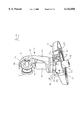
- FIG. 1 shows the device of the invention in a schematical manner and in a perspective view
- FIG. 2 shows the device of FIG. 1 in another position
- FIG. 3 shows a detail of the device of FIG. 1
- FIG. 4 shows the device of FIG. 1 with further details in a partially sectioned perspective view
- FIGS. 5 and 6 show longitudinal sections of a chucking assembly of the device of FIG. 1 in two different positions, respectively;
- FIGS. 7 and 8 show an alternative embodiment of the chuck of FIG. 5;
- FIGS. 9 and 10 show a second alternative embodiment of the chucks of FIGS. 5 or 7;
- FIG. 11 shows an alternative embodiment of the chuck of FIG. 9
- FIG. 12 shows further details of the device of FIG. 1 in a partly sectioned perspective view
- FIG. 13 shows further details of the device of FIG. 1 in a partly sectioned perspective view
- FIGS. 14 and 15 show further details of the device of the invention according to FIG. 1 in a longitudinal section.
- FIG. 1 shows the essential elements of the device of the invention, i.e. chuck head 1 including chuck 2 for the retention of the sharpened instrument, the chuck head being fastened to an arcuate chuck head holder 3, as well as grinding head 4 including grinding wheel 5, the grinding head being pivotably fastened to rotary plate 6.
- chuck head holder 3 may be turned up 30° and down 45° from the horizontal position according to FIG. 3. It is understood that the indicated values do not represent limitations but are useful values for the intended purposes.
- FIG. 3 further shows that chuck head is rotatable relative to chuck head holder 3 about its central axis, the maximum rotation being 20° in each direction and the different positions being determined by snap means in the form of spring-loaded balls, for example. While this rotary movement is necessary for the sharpening of certain instrument surfaces, other instruments may require different positions and rotational angles.
- the chuck is an important element of a grinding apparatus as it is to ensure a precise and firm chucking of the dental instrument.
- the grinding wheel may be chucked and aligned in some way, the dental instrument is held and guided manually and only a hand rest is possibly provided.
- the precision of the operation of sharpening the cutting surface essentially depends on the skill of the dentist, and it is therefore not reproducible.
- it is necessary to chuck the instrument in a precisely defined position.
- FIGS. 4 to 11 show some embodiments of a chucking assembly which shall now be explained in more detail.
- FIGS. 5 and 6 are most suitable for the description of the chucking assembly of the invention.
- the figures show part of a dental instrument, e.g. a curette 7, whose first shank portion 8 behind cutting edge 9 is chucked, the point 10 of the instrument of FIG. 5 or 6 facing right, i.e. the operator.
- the chucking assembly comprises a thrust bolt 15 comprising a central supporting portion 18, which runs in a chuck housing 20.
- the thrust bolt On its side opposite the chucked instrument, the thrust bolt carries a thrust sleeve 11 which is actuated by a chucking member in the form of an eccentric disk with a handle 13. This eccentric disk may also be in the form of a wheel or the like.
- Disk springs 16 are disposed between thrust sleeve 11 and supporting portion 18 of the thrust bolt, whereas the other part of the thrust bolt, i.e. chucking portion 17, is under the action of a pressure spring 19 which rests on supporting portion 18 and on the inside of the housing.
- a positioning bar 14 extends underneath the thrust bolt.
- FIG. 5 shows the loading position, and it appears that positioning bar 14 is in the advanced position with the back of cutting edge 9 of dental instrument 7 resting thereon in order to ensure a clearly defined height adjustment in the clamping operation.
- the instrument is passed through chuck opening 21 in the foremost section of the chuck housing, the clamping surface of the chuck opening forming a part of the proper chuck.
- thrust bolt 15 is first advanced, the front end of its chuck portion 17 pressing the instrument against the clamping surface of opening 21 and thus clamping the instrument.
- positioning bar 14 is retracted, thus allowing an unhindered treatment of the dental instrument in any desired position.
- the clamping surface of the chuck opening of the chuck according to FIGS. 5 and 6 may e.g. comprise a conical recess while the thrust bolt has a rounded end, so that a three-point rest of the instrument shank may be obtained.
- FIGS. 7 and 8 describe an alternative embodiment where the front end of thrust bolt 24 comprises a head 25 having a semicircular recess 26 in which a rocker 27 is disposed whose semicircular back side 28 is displaceable in semicircular recess 26 and comprises two clamping corners 29 which are capable of clamping the shank of the instrument in conjunction with the clamping surface.
- thrust bolt 24 runs in the chuck housing 30 which is provided at its front end with chuck member 31 and the clamping surface which cooperates with the thrust bolt.
- these elements are shown in the assembled condition in a sectional view. A precise and firm retention of the instrument is always ensured by the fact that the rocker is freely displaceable in the head of the thrust bolt.
- FIG. 10 illustrates another alternative embodiment where the displaceable rocker is replaced by an elastic element 32 on thrust bolt 33 while chuck opening 34 of chuck housing 35 is essentially the same as in the previous example.
- elastic element 32 consists of a plate having a respective incision 37 on both sides, thus allowing both an axial and also a certain transversal movement of the plate for best possible adaptation of clamping points 38 to the dental instrument.
- eccentric disk 12 of the clamping member does not actuate a thrust sleeve but a wheel 39 which is rotatably secured in a bearing element 40 and connected to rear portion 41 of thrust bolt 33.
- the thrust bolt is actuated by the same springs as in the previous examples, and it is illustrated in the assembled condition in the sectional view of FIG. 10.
- FIG. 11 shows an alternative embodiment of FIG. 9 where the head 42 of thrust bolt 43 is provided with a plate 44 which extends in the longitudinal axis and which is so elastic that the two clamping points 38 are also capable of adapting to the shank of the dental instrument in order to ensure a safe retention in this manner.
- the other elements and the assembly correspond to the previous example according to FIGS. 9 and 10.
- FIGS. 5, 6, 8, and 10 show clearly that the axis of the chuck opening, resp. of the clamping surface, is not perpendicular to the longitudinal axis of the chuck head but includes and angle of approx. 80° thereto.
- FIG. 12 The attachment of chuck head support 3 is illustrated in FIG. 12, in particular.
- the support is guided in a base 45 of U-shaped cross-section.
- the end 45A of the base where support 3 is guided is raised.
- the internal surface of the two shanks 46 and 47 of the base is provided with guiding pins 48 and 49.
- the upper guiding pins 48 are disposed near the ends of the shanks, and the second guiding pins 49 below the first ones.
- the guiding pins taper outwardly, and a respective pair of them engages in each guiding groove 50, the latter tapering inwardly and extending along the semicircular chuck head support 3, as illustrated in FIG. 12 in particular.
- the raised configuration of the end of the base comprising the guiding pins and the disposition of the guiding pins allow to swivel the chuck support across the full range etween +30° up and -45° down from the horizontal direction without making the free end of the support protrude from the rotary table.
- the support should be guided and held with minimum play. This may e.g. be obtained if the guiding pins 51 and 52 are rigidly mounted in one shank, e.g. in shank 47, and the other two guiding pins 48 and 49 are spring-loaded.
- FIG. 12 further illustrates the manner in which rotary table 6 carrying grinding head 4 with grinding wheel 5 is rotatably mounted on base 45.
- the surface 53 of base 45 comprises four bearing plugs 54 whose surfaces are coated with a particularly slidable material.
- the rotary table runs on these bearing plugs via a rib 55.
- Rotary table 6 further comprises a peg 56, as illustrated in FIG. 13, which runs in a non-represented bearing sleeve which is fastened in a corresponding opening of the base from the underside and serves as a radial bearing of the rotary table.
- FIG. 13 further shows that sliding rib 55 is followed on the outside by another rib 57 whose height is not constant over the entire circumference and which therefore actuates a microswitch 58, see FIG. 4, in the course of the rotation of the rotary table in order to reverse the rotating direction of the grinding wheel in certain positions of the rotary table.
- the surface of the rotary table comprises a hand rest 84, see FIG. 1.
- Bearing 60 of the grinding head is disposed in a central recess of rotary table 6.
- Grinding head bearing 60 which is made in one piece with peg 56, is secured in an opening 61 at the center of the rotary table and comprises two bearing walls 62 in each of which two openings are provided, the lower openings 63 being intended to receive axle 64 which serves as a pivot of the grinding head.
- the upper openings 65 serve to receive a pin 66 to which a tension spring 67 is secured.
- Grinding head 4 comprises a grinding head casing 68, grinding wheel 5 being disposed in the upper section thereof while the drive of the grinding wheel is disposed inside the casing.
- grinding head casing 68 comprises two bearing members 69 whose plane extends in parallel to the axis of the grinding wheel and which are each provided with a respective recess 70 on the grinding wheel side in order to engage behind pivot 64, as shown in FIGS. 14 and 15.
- the two bearing members 69 are each provided with a second recess 71 which serves to receive a pin 72 to which tension spring 67 is secured.
- An appropriate dimensioning of the tension spring allows to establish and maintain the desired constant grinding pressure of the grinding wheel.
- FIG. 3 shows that the sides of bearing walls 62 opposite the grinding wheel comprise two steps 73 and 74 in which pin 72 of the tension spring can engage, the pin being engaged in the lower step 74 in the rest position, see FIG. 14, and in the upper step 73 in the active position.
- the plane of grinding wheel surface 5A is inclined about 15° with respect to the mid-perpendicular M.
- FIGS. 13 to 15 further illustrate the drive of the grinding wheel. It is advantageous to use a wheel and disk drive, whose construction is very simple and whose operation noise is relatively low.
- electric motor 75 On its output shaft, electric motor 75 is provided with a friction wheel 76 which is equipped e.g. with a rubber-elastic ring or with an O-ring 77.
- Grinding wheel support 78 comprises an axle 79 which is supported in the grinding head casing perpendicularly to the longitudinal axis thereof and about perpendicularly to the output shaft of the electric motor at two points 80 and 81.
- a friction disk 82 is secured to axle 79 which cooperates with friction wheel 76.
- the desired rotational speed of the grinding wheel is determined by the speed of the electric motor and by the multiplication resp. reduction ratio between the friction wheel and the friction disk.
- the grinding wheel may be fastened to the grinding wheel support in different ways.
- a friction wheel and a friction disk it is also possible to use an angular gear, e.g. an angular gear which is mounted on the output shaft of the electric motor and which acts on an angular gear on the grinding wheel axle, in which case a 90° gear may be used.
Landscapes
- Engineering & Computer Science (AREA)
- Mechanical Engineering (AREA)
- Health & Medical Sciences (AREA)
- General Health & Medical Sciences (AREA)
- Oral & Maxillofacial Surgery (AREA)
- Surgery (AREA)
- Dental Tools And Instruments Or Auxiliary Dental Instruments (AREA)
Abstract
Description
Claims (10)
Applications Claiming Priority (4)
| Application Number | Priority Date | Filing Date | Title |
|---|---|---|---|
| EP97810935 | 1997-12-01 | ||
| EP97810935 | 1997-12-01 | ||
| EP98810336A EP0919327B1 (en) | 1997-12-01 | 1998-04-17 | Apparatus for sharpening dental instruments |
| EP98810336 | 1998-04-17 |
Publications (1)
| Publication Number | Publication Date |
|---|---|
| US6142856A true US6142856A (en) | 2000-11-07 |
Family
ID=26148100
Family Applications (1)
| Application Number | Title | Priority Date | Filing Date |
|---|---|---|---|
| US09/199,458 Expired - Lifetime US6142856A (en) | 1997-12-01 | 1998-11-25 | Sharpening device for dental instruments |
Country Status (9)
| Country | Link |
|---|---|
| US (1) | US6142856A (en) |
| EP (1) | EP0919327B1 (en) |
| JP (1) | JPH11226036A (en) |
| AT (1) | ATE281273T1 (en) |
| BR (1) | BR9804976A (en) |
| DE (1) | DE59812216D1 (en) |
| DK (1) | DK0919327T3 (en) |
| ES (1) | ES2230664T3 (en) |
| PL (1) | PL189414B1 (en) |
Cited By (7)
| Publication number | Priority date | Publication date | Assignee | Title |
|---|---|---|---|---|
| US6808441B2 (en) | 2003-02-07 | 2004-10-26 | Nordent Manufacturing, Inc. | Dental tool sharpener and method of use |
| US20050183545A1 (en) * | 2004-02-19 | 2005-08-25 | Huntington Kent L. | Cutting chain grinder and method of grinding |
| US20110281505A1 (en) * | 2009-03-19 | 2011-11-17 | Hofmann Karl Robert | Method and device for grinding a continuous casting product |
| US20120108145A1 (en) * | 2009-07-16 | 2012-05-03 | Arnold Deppeler | Device and method for sharpening dental curettes |
| US10513003B2 (en) * | 2017-06-13 | 2019-12-24 | Dalian University Of Technology | Precision lapping and polishing device for external cylindrical surface of the disk part and its taper error adjustment method thereof |
| CN112518484A (en) * | 2020-11-30 | 2021-03-19 | 孙庆峰 | Automobile rotating shaft welding forming surface refining treatment system |
| CN113146372A (en) * | 2020-11-24 | 2021-07-23 | 太仓治誓机械设备科技有限公司 | Drilling tool maintenance and curing equipment for machining in mechanical production workshop |
Families Citing this family (6)
| Publication number | Priority date | Publication date | Assignee | Title |
|---|---|---|---|---|
| CN107225456B (en) * | 2017-06-28 | 2019-03-22 | 芜湖德丰汽车零部件有限公司 | A kind of plate deburring grinding device |
| CN107150275A (en) * | 2017-07-14 | 2017-09-12 | 芜湖德丰汽车零部件有限公司 | A kind of grinding apparatus |
| CN108857888A (en) * | 2018-07-17 | 2018-11-23 | 益文杰 | A kind of fixed device of ceramic tile polishing |
| CN111215971B (en) * | 2020-03-09 | 2020-12-04 | 深圳市超达成包装制品有限公司 | Intelligent circular knife secondary polishing equipment |
| CN112692711A (en) * | 2020-12-30 | 2021-04-23 | 深圳市杰昌实业有限公司 | Metal surface treatment burnishing device |
| CN115302338A (en) * | 2022-10-12 | 2022-11-08 | 徐州沣收喷灌设备有限公司 | Cylinder body trompil equipment of polishing for plunger pump processing |
Citations (8)
| Publication number | Priority date | Publication date | Assignee | Title |
|---|---|---|---|---|
| US3902283A (en) * | 1974-01-18 | 1975-09-02 | Philip D Bean | Gem grinder with approach control means |
| US4637775A (en) * | 1983-12-15 | 1987-01-20 | Mitsubishi Denki Kabushiki Kaisha | Industrial robot device |
| EP0307740A2 (en) * | 1987-09-17 | 1989-03-22 | Mikrona Ag | Device for sharpening paradental instruments |
| US5058324A (en) * | 1990-01-24 | 1991-10-22 | Snellen Paul F | Gem stone facet forming apparatus |
| US5070654A (en) * | 1988-10-17 | 1991-12-10 | C.M.E. Blasting & Mining Equipment, Ltd. | Self-centering arrangement for grinding the hardmetal pins of drill bits |
| WO1992009403A1 (en) * | 1990-11-26 | 1992-06-11 | Quétin, Roswitha | Device for sharpening, grinding or polishing dental, periodontal and/or surgical instruments |
| DE4307679A1 (en) * | 1992-03-17 | 1993-08-26 | Rudolf Hegen | Electronically controlled grinder for re-tipping dental instruments - has coded instrument holding cassette and programmed twin disc grinding head operating in controlled circular arc around instrument tip. |
| US5297362A (en) * | 1992-10-09 | 1994-03-29 | Wykoff Gerald L | Faceting head apparatus for working colored stones |
Family Cites Families (8)
| Publication number | Priority date | Publication date | Assignee | Title |
|---|---|---|---|---|
| JPS48607Y1 (en) * | 1968-12-14 | 1973-01-09 | ||
| JPS48102389A (en) * | 1972-04-12 | 1973-12-22 | ||
| JPS5822218U (en) * | 1981-07-30 | 1983-02-10 | 日立精機株式会社 | clamp device |
| JPS60155352A (en) * | 1984-01-24 | 1985-08-15 | Chuo Seisakusho:Kk | Polisher for t-shaped work |
| JPS6370837U (en) * | 1986-10-29 | 1988-05-12 | ||
| DE3855976T2 (en) * | 1987-09-04 | 1997-12-04 | Gunnar K Svanberg | System for dental curettes and sharpening machine |
| JP2500173B2 (en) * | 1992-04-03 | 1996-05-29 | 住友金属鉱山株式会社 | Clamping device for cutting bending members |
| JPH0744422Y2 (en) * | 1992-09-24 | 1995-10-11 | 興和化成株式会社 | Self-aligning clamp device |
-
1998
- 1998-04-17 DK DK98810336T patent/DK0919327T3/en active
- 1998-04-17 EP EP98810336A patent/EP0919327B1/en not_active Expired - Lifetime
- 1998-04-17 DE DE59812216T patent/DE59812216D1/en not_active Expired - Lifetime
- 1998-04-17 AT AT98810336T patent/ATE281273T1/en not_active IP Right Cessation
- 1998-04-17 ES ES98810336T patent/ES2230664T3/en not_active Expired - Lifetime
- 1998-11-25 US US09/199,458 patent/US6142856A/en not_active Expired - Lifetime
- 1998-12-01 JP JP10342051A patent/JPH11226036A/en active Pending
- 1998-12-01 BR BR9804976-3A patent/BR9804976A/en not_active IP Right Cessation
- 1998-12-01 PL PL98330006A patent/PL189414B1/en not_active IP Right Cessation
Patent Citations (8)
| Publication number | Priority date | Publication date | Assignee | Title |
|---|---|---|---|---|
| US3902283A (en) * | 1974-01-18 | 1975-09-02 | Philip D Bean | Gem grinder with approach control means |
| US4637775A (en) * | 1983-12-15 | 1987-01-20 | Mitsubishi Denki Kabushiki Kaisha | Industrial robot device |
| EP0307740A2 (en) * | 1987-09-17 | 1989-03-22 | Mikrona Ag | Device for sharpening paradental instruments |
| US5070654A (en) * | 1988-10-17 | 1991-12-10 | C.M.E. Blasting & Mining Equipment, Ltd. | Self-centering arrangement for grinding the hardmetal pins of drill bits |
| US5058324A (en) * | 1990-01-24 | 1991-10-22 | Snellen Paul F | Gem stone facet forming apparatus |
| WO1992009403A1 (en) * | 1990-11-26 | 1992-06-11 | Quétin, Roswitha | Device for sharpening, grinding or polishing dental, periodontal and/or surgical instruments |
| DE4307679A1 (en) * | 1992-03-17 | 1993-08-26 | Rudolf Hegen | Electronically controlled grinder for re-tipping dental instruments - has coded instrument holding cassette and programmed twin disc grinding head operating in controlled circular arc around instrument tip. |
| US5297362A (en) * | 1992-10-09 | 1994-03-29 | Wykoff Gerald L | Faceting head apparatus for working colored stones |
Cited By (11)
| Publication number | Priority date | Publication date | Assignee | Title |
|---|---|---|---|---|
| US6808441B2 (en) | 2003-02-07 | 2004-10-26 | Nordent Manufacturing, Inc. | Dental tool sharpener and method of use |
| US20050183545A1 (en) * | 2004-02-19 | 2005-08-25 | Huntington Kent L. | Cutting chain grinder and method of grinding |
| US7175512B2 (en) * | 2004-02-19 | 2007-02-13 | Blount, Inc. | Cutting chain grinder and method of grinding |
| US20110281505A1 (en) * | 2009-03-19 | 2011-11-17 | Hofmann Karl Robert | Method and device for grinding a continuous casting product |
| US8900035B2 (en) * | 2009-03-19 | 2014-12-02 | Sms Logistiksysteme Gmbh | Method and device for grinding a continuous casting product |
| US20120108145A1 (en) * | 2009-07-16 | 2012-05-03 | Arnold Deppeler | Device and method for sharpening dental curettes |
| US9126302B2 (en) * | 2009-07-16 | 2015-09-08 | Arnold Deppeler | Device and method for sharpening dental curettes |
| US10513003B2 (en) * | 2017-06-13 | 2019-12-24 | Dalian University Of Technology | Precision lapping and polishing device for external cylindrical surface of the disk part and its taper error adjustment method thereof |
| CN113146372A (en) * | 2020-11-24 | 2021-07-23 | 太仓治誓机械设备科技有限公司 | Drilling tool maintenance and curing equipment for machining in mechanical production workshop |
| CN112518484A (en) * | 2020-11-30 | 2021-03-19 | 孙庆峰 | Automobile rotating shaft welding forming surface refining treatment system |
| CN112518484B (en) * | 2020-11-30 | 2023-01-13 | 天津摩天电子有限公司 | Automobile rotating shaft welding forming surface refining treatment system |
Also Published As
| Publication number | Publication date |
|---|---|
| DK0919327T3 (en) | 2005-01-31 |
| PL330006A1 (en) | 1999-06-07 |
| JPH11226036A (en) | 1999-08-24 |
| DE59812216D1 (en) | 2004-12-09 |
| EP0919327B1 (en) | 2004-11-03 |
| BR9804976A (en) | 1999-11-16 |
| ES2230664T3 (en) | 2005-05-01 |
| EP0919327A3 (en) | 2002-01-16 |
| ATE281273T1 (en) | 2004-11-15 |
| PL189414B1 (en) | 2005-08-31 |
| EP0919327A2 (en) | 1999-06-02 |
Similar Documents
| Publication | Publication Date | Title |
|---|---|---|
| US6142856A (en) | Sharpening device for dental instruments | |
| US20080045126A1 (en) | Manual Grinding Tool | |
| US20230167844A1 (en) | Adjustable Stroke Device With Cam | |
| US5295328A (en) | Device for the sharpening, grinding and polishing of dental, parodental and/or surgical instruments | |
| JPH02279266A (en) | Device for grinding tip of tungsten electrode | |
| JPS61260971A (en) | Grinding holder for grinding drilling tool such as drill | |
| KR20190094560A (en) | Processing device of tungsten electrode | |
| JP3570833B2 (en) | Drill polishing method | |
| JPS6325905B2 (en) | ||
| JPS6116016Y2 (en) | ||
| JPH07314331A (en) | Grinding wheel cover device of grinder | |
| CA2188158A1 (en) | Method and device for sharpening tools, particularly dental hand instruments | |
| JP3088251B2 (en) | Groove processing machine for inner peripheral surface of carrier hole of lap carrier | |
| JP2020066095A (en) | Rotary dresser | |
| JPH0719705Y2 (en) | Tool polishing jig | |
| KR20040077237A (en) | grinding material fixing jig | |
| JP3829042B2 (en) | Work support for polishing equipment | |
| PL177948B1 (en) | Apparatus for aharpening cutting edges of cutting tools especially those used in dental instruments | |
| JPH0618772Y2 (en) | Hand grinder | |
| SU1431916A1 (en) | Arrangement for grinding cylindrical and conical surfaces of part | |
| JP2519241Y2 (en) | Disk polishing and grinding equipment | |
| JPH0767643B2 (en) | Workpiece check device | |
| JPS58171252A (en) | Cam grinder | |
| JPH06312352A (en) | Drill grinder | |
| KR860003032Y1 (en) | Apparatus of capillary processing centering |
Legal Events
| Date | Code | Title | Description |
|---|---|---|---|
| AS | Assignment |
Owner name: HAWE NEOS DENTAL, SWITZERLAND Free format text: ASSIGNMENT OF ASSIGNORS INTEREST;ASSIGNOR:ROMHILD, LUDWIG;REEL/FRAME:009635/0077 Effective date: 19981115 |
|
| AS | Assignment |
Owner name: HAWE NEOS DENTAL DR. H. V. WEISSENFLUH AG, SWITZER Free format text: RE-RECORDATION OF ASSIGNMENT PREVIOUSLY RECORDED ON REEL 009634, FRAMES 0077 AND 0078, TO CORRECT THE ASSIGNEE'S NAME.;ASSIGNOR:ROMHILD, LUDWIG;REEL/FRAME:010424/0466 Effective date: 19981115 |
|
| STCF | Information on status: patent grant |
Free format text: PATENTED CASE |
|
| CC | Certificate of correction | ||
| AS | Assignment |
Owner name: CREDIT SUISSE FIRST BOSTON, NEW YORK Free format text: SECURITY AGREEMENT;ASSIGNOR:HAWE NEOS DENTAL SA;REEL/FRAME:012991/0127 Effective date: 20020606 |
|
| FPAY | Fee payment |
Year of fee payment: 4 |
|
| AS | Assignment |
Owner name: HAWE NEOS DENTAL SA, SWITZERLAND Free format text: RELEASE BY SECURED PARTY;ASSIGNOR:CREDIT SUISSE FIRST BOSTON (N/K/A CREDIT SUISSE, CAYMAN ISLANDS BRANCH);REEL/FRAME:017519/0386 Effective date: 20060323 |
|
| FEPP | Fee payment procedure |
Free format text: PAYOR NUMBER ASSIGNED (ORIGINAL EVENT CODE: ASPN); ENTITY STATUS OF PATENT OWNER: LARGE ENTITY |
|
| FPAY | Fee payment |
Year of fee payment: 8 |
|
| FPAY | Fee payment |
Year of fee payment: 12 |