US6137277A - Static voltage regulator - Google Patents
Static voltage regulator Download PDFInfo
- Publication number
- US6137277A US6137277A US09/429,622 US42962299A US6137277A US 6137277 A US6137277 A US 6137277A US 42962299 A US42962299 A US 42962299A US 6137277 A US6137277 A US 6137277A
- Authority
- US
- United States
- Prior art keywords
- voltage
- regulator
- booster
- input
- primary
- Prior art date
- Legal status (The legal status is an assumption and is not a legal conclusion. Google has not performed a legal analysis and makes no representation as to the accuracy of the status listed.)
- Expired - Fee Related
Links
Images

Classifications
-
- G—PHYSICS
- G05—CONTROLLING; REGULATING
- G05F—SYSTEMS FOR REGULATING ELECTRIC OR MAGNETIC VARIABLES
- G05F1/00—Automatic systems in which deviations of an electric quantity from one or more predetermined values are detected at the output of the system and fed back to a device within the system to restore the detected quantity to its predetermined value or values, i.e. retroactive systems
- G05F1/10—Regulating voltage or current
- G05F1/12—Regulating voltage or current wherein the variable actually regulated by the final control device is ac
- G05F1/14—Regulating voltage or current wherein the variable actually regulated by the final control device is ac using tap transformers or tap changing inductors as final control devices
- G05F1/16—Regulating voltage or current wherein the variable actually regulated by the final control device is ac using tap transformers or tap changing inductors as final control devices combined with discharge tubes or semiconductor devices
- G05F1/20—Regulating voltage or current wherein the variable actually regulated by the final control device is ac using tap transformers or tap changing inductors as final control devices combined with discharge tubes or semiconductor devices semiconductor devices only
Definitions
- the present invention relates to a voltage regulator which regulates the AC voltage at its load terminals in response to variations in source voltage.
- the present invention relates to a medium voltage voltage regulator employing a feed forward approach for regulating load voltage.
- the conventional medium power voltage regulator consists of a booster transformer, a regulator transformer having a multi-tap secondary winding, electro-mechanical tap switches coupled between the booster transformer primary and respective taps of the regulator transformer secondary windings, and a mechanical crowbar switch connected across the booster transformer primary.
- the secondary of the booster transformer is connected in series with the power distribution line and a load (such as electronic equipment), and the primary of the regulator transformer is connected across the source side of the distribution line in advance of the booster transformer.
- the crowbar switch is closed, causing the booster transformer to appear as a simple inductance in series with the load.
- Control logic monitors the load voltage, and closes one of the tap switches in response to a supply event at the load.
- the crowbar switch is then opened so that the voltage from the regulator transformer secondary appears across the primary of the booster transformer and becomes added to the source voltage.
- the particular tap switch to be closed is selected so that the voltage induced in the booster transformer secondary is of sufficient magnitude and polarity so as to counteract the supply event.
- solid-state static voltage regulators Due to the rapid response times of solid-state switches over mechanical switches, solid-state static voltage regulators (SVRs) have been developed recently as a replacement for the conventional mechanical voltage regulator.
- SVRs solid-state static voltage regulators
- Once such voltage regulator is taught by Schoendube in U.S. Pat. No. 3,732,486, and consists of a booster transformer, a multi-tap shunt transformer, and a series of thyristor tap switches coupled between one end of the primary winding of the booster transformer and a respective tap of the shunt transformer.
- the other end of the primary winding of the booster transformer is connected to a half H-bridge circuit which allows the voltage regulator to operate either in boost or buck mode.
- the secondary winding of the booster transformer is connected in series between the input terminal and the load terminal, while the shunt transformer is connected between the input terminal and a voltage reference.
- the regulator includes a bypass thyristor switch connected across the booster transformer primary.
- a line voltage is applied to the input terminal of the Schoendube voltage regulator. If the output voltage is within tolerance, the bypass thyristor switch is closed, thereby shorting the primary of the booster transformer and providing unity voltage gain.
- the H-bridge is configured for boost mode, and one of the tap switches is closed, causing the bypass thyristor to be commutated off and a voltage to be induced into the secondary winding of the booster transformer which adds to the voltage at the input terminal.
- the H-bridge is configured for buck mode, and one of the tap switches is closed, causing a voltage to be induced into the secondary winding of the booster transformer which subtracts from the voltage at the input terminal.
- the output transformer includes a primary winding, an output winding, and a multi-tap winding.
- the secondary winding of the booster transformer is connected in series with the input terminals and the primary winding of the output transformer, and the output winding of the output transformer is connected to the output terminals.
- the switch matrix comprises a series of triac switches each connected between the primary winding of the booster transformer and a respective tap of the multi-tap winding.
- a line voltage is applied to the input terminals of the Flynn voltage regulator.
- a control circuit monitors the peak voltage at the output terminals each half cycle, and provides gating signals to the switch matrix to either boost the output voltage (when operating in boost mode) or reduce the output voltage (when operating in buck mode).
- Flynn does not address the problem of transients which might be induced into the load when the triacs are switched. Accordingly, there remains a need for a medium-voltage voltage regulator which provides a shorter response time than the conventional mechanical voltage regulator, and reduces the risk of transients being induced into the load when the load voltage is corrected.
- the static voltage regulator comprises an input, an output, a booster transformer, a regulator transformer, an electronic switching system and a control system.
- the booster transformer includes a booster primary winding and a booster secondary winding.
- the booster secondary is provided in series with the input and the output so as to produce an output voltage.
- the regulator transformer includes a regulator primary winding and a regulator secondary winding.
- the regulator primary is electrically coupled to the output.
- the electronic switching system is coupled between the regulator secondary and the booster primary for providing a voltage to the booster primary.
- the control system includes a voltage sensor for sensing a voltage at the input, and a gating system coupled to the switching system for switching the output voltage in response to changes in the sensed input voltage.
- the voltage regulator also includes a notch filter coupled to the booster transformer for reducing transients induced in the booster transformer when the output voltage is switched.
- the regulator secondary includes a plurality of voltage taps, the taps including a voltage boost tap for increasing the output voltage and a voltage buck tap for decreasing the output voltage.
- the electronic switching system comprises a plurality of electronic switches. Each switch includes a gating input for controlling a conduction interval thereof and is coupled between the booster primary and a respective one of the plurality of taps for providing one of a plurality of voltages to the booster primary.
- the gating system is coupled to the voltage sensor and the gating inputs for switching the output voltage in response to changes in the sensed input voltage, and is configured to open a conducting one of the electronic switches prior to closing a non-conducting one of the electronic switches.
- FIG. 1 is a schematic diagram of one phase of a three-phase static voltage regulator according to the present invention, depicting the booster transformer, the regulator transformer, the electronic switching system, the control system, and the notch filter; and
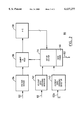
- FIG. 2 is a block diagram of the control system shown in FIG. 1.
- the static voltage regulator denoted generally as 100, is shown comprising an input port 102 for coupling to a voltage source, such as a power distribution line, an output port 104 for coupling to a load (not shown), a booster transformer 110, a regulator transformer 112, an electronic switching system 114 connected between the booster transformer 110 and the regulator transformer 112, a control system 116 coupled to the switching system 114, and a notch filter 118 coupled to the booster transformer 110.
- the booster transformer 110 has a booster primary winding 120 and a booster secondary winding 122.
- the booster secondary 122 is provided in series with the input port 102 and the output port 104.
- the regulator transformer 112 has a regulator primary winding 124 and a regulator secondary winding 126.
- the regulator primary 124 is connected to the output port 104, and the regulator secondary 126 includes a plurality of taps 126a, 126b, 126c, . . . 126n each providing a discrete analog output voltage.
- the electronic switching 114 system comprises a plurality of electronic tap switches 128.
- Each electronic switch 128 is connected between a first end 120a of the booster primary 120 and a respective one of the taps 126 for providing one of a plurality of voltages to the booster primary 120.
- the second end 120b of the booster primary 120 is connected directly to one of the taps, tap 126m in the example shown.
- taps 126a, 126b, . . . , 126m-1 are configured to provide a voltage to the booster primary 120 which boosts or increases the output voltage of the regulator 100.
- the regulator transformer secondary include a plurality of taps 126, with an electronic tap switch 128 connected to each tap 126. Instead, in lower voltage applications, the regulator transformer secondary may produce a single voltage, and the electronic switching system 114 may comprise an amplifier for providing one of a plurality of voltages to the booster primary 120.
- the electronic switching system 114 also includes an electronic crowbar switch 130 connected across the booster primary 120.
- each electronic switch 128, 130 comprises a pair of SCR switches connected back-to-back.
- other electronic switches including FETs, IGBTs, GTOs, IGCTs, triacs and bipolar transistors, may be used instead of SCRs.
- Each electronic switch 128, 130 includes a pair of gating inputs 132 for controlling a conduction interval of the switch, extending between the respective electronic switch and the control system 116.
- the control system 116 includes an analog voltage sensor 134 for sensing a voltage at the input port 102, a sample-and-hold circuit 136 connected to the analog output of the voltage sensor 134, an analog-to-digital converter 138 connected to the output of the sample-and-hold circuit 136, a zero-crossing voltage detector 140 for detecting zero voltage crossings of the input voltage, and a zero-crossing current sensor 142 for detecting zero current crossings through the electronic switches 128, 130.
- the current sensor 142 is coupled to the first end 120a of the booster primary 120, however it may be repositioned to other nodes of the regulator circuit if desired.
- the control system 116 also comprises a microproccssor-based gating system 144 which includes an interrupt input for receiving an interrupt from the zero-crossing detector 140, a data input for receiving a control signal from the current sensor 142, a data input port for receiving digitized input voltage data from the analog-to-digital converter 138, a control output for triggering the sample-and-hold circuit 136, and a gate driver 146 connected to the gating inputs 132 of the electronic switching system 114 for switching the output voltage of the regulator 100 in response to changes in the sensed input voltage.
- the regulator 100 may include a separate control system 116 for each phase of the input voltage, or may include a single control system for all phases.
- the notch filter 118 comprises a series RLC filter, and is connected across the booster primary 120. Two purposes of the filter 118 are to reduce notches and transients induced in the booster transformer 120 during switching dead times and to establish an initial load voltage while all the electronic switches are off. Accordingly, other suitable filter implementations will be apparent to those of ordinary skill, and are intended to fall within the scope of the invention.
- the voltage sensor 134 senses the input voltage at the input port 102, preferably at a rate of 32 times per cycle of input voltage. Simultaneously, the zero-crossing detector 140 monitors the input voltage for a zero-crossing. Once a zero-crossing of the input voltage is detected, the zero-crossing detector 140 generates an interrupt to the gating system 144. Based on the fundamental frequency of the input voltage and the sample rate of the voltage sensor 134, the gating system 144 issues a command to the sample-and-hold circuit 136 which is timed so that the sample-and-hold circuit 136 samples the output of the voltage sensor 134 at the instantaneous peak value of the input voltage, each half cycle of the input voltage.
- the analog output of the sample-and-hold circuit 136 is converted to digital form by the analog-to-digital converter 138, with the digitized output being input to the gating system 144.
- the gating system 144 compares the sensed input voltage against an expected nominal value. Based on the deviation of the sensed input voltage from the nominal value, the duration of the deviation, and the voltage regulation required by the load connected to the output port 104, the gating system 144 then carries out the steps necessary, if any, to counteract the effect an input voltage variation may have on the output voltage of the regulator 100.
- the regulator 100 If the sensed input voltage is above a minimum threshold value, preferably 90% of its nominal value, the regulator 100 is operated in no-boost mode. In this mode, the control system 116 closes the crowbar switch 130 and opens all of the tap switches 128. Consequently, during normal line voltage conditions, the booster transformer 110 appears as a short circuit between the input and output ports 102, 104, not including the leakage inductances in series with the load.
- a minimum threshold value preferably 90% of its nominal value
- the control system 116 first determines which tap switch 128 to close. As will be apparent, the appropriate tap switch 128 is selected so as to boost the output voltage of the generator 100 back above the minimum threshold value.
- the control system 116 removes the gating signal from the crowbar switch 130, causing the crowbar switch 130 to open when the current through the respective SCRs drops to zero.
- the gating system 144 applies a gating signal to the selected tap switch 128 before the next zero crossing of the input voltage. The magnitude of the voltage spike which would otherwise be induced across the booster transformer 120 by open-circuiting the booster primary 120 is reduced by the presence of notch filter 118.
- the notch filter 118 also limits the magnitude of the voltage "notch" which would otherwise be present between the instant the crowbar switch 130 is switched off and the instant the selected tap switch 128 is turned on. Further, the risk of damage to the crowbar switch 130 at turn-on which would otherwise be present as a result of the rate of change of current through the SCRs exceeding a maximum limit is reduced due to the presence of the notch filter 118, and in particular the inductive component of the notch filter 118.
- the control system 116 again determines the appropriate tap 128 to close based on the deviation of the input voltage from the nominal value. After the current sensor 142 signals the gating system 144 that the conducting tap switch 128 has stopped conducting, the gating system 144 applies a gating signal to the selected tap switch 128 before the next zero crossing of the input voltage. This process continues, with the gating system 144 continuously monitoring the input voltage and determining the appropriate tap switch 128 to close each half cycle. If the undervoltage conditions disappears, the gating system 144 removes the gating signal from the conducting tap switch 128. After the current sensor 142 signals the gating system 144 that the conducting tap switch 128 has stopped conducting, the gating system 144 applies a gating signal to the crowbar switch 130 before the next zero crossing of the input voltage.
- the control system 116 determines which tap switch 128 to close. As will be apparent, the appropriate tap switch 128 is selected so as to reduce the output voltage of the generator 100 back below the maximum threshold value. The control system 116 then removes the gating signal from the crowbar switch 130, causing the crowbar switch 130 to open when the current through the respective SCRs drops to zero. After the current sensor 142 signals the gating system 144 that the crowbar switch 130 has stopped conducting, the gating system 144 applies a gating signal to the selected tap switch 128 before the next zero crossing of the input voltage. As a result, the regulator responds to an overvoltage condition in about one quarter of an input voltage cycle.
- the control system 116 again determines the appropriate tap 128 to close based on the deviation of the input voltage from the nominal value. After the current sensor 142 signals the gating system 144 that the conducting tap switch 128 has stopped conducting, the gating system 144 applies a gating signal to the selected tap switch 128 before the next zero crossing of the input voltage. This process continues, with the gating system 144 continuously monitoring the input voltage and determining the appropriate tap switch 128 to close each half cycle. If the overvoltage conditions disappears, the gating system 144 removes the gating signal from the conducting tap switch 128. After the current sensor 142 signals the gating system 144 that the conducting tap switch 128 has stopped conducting, the gating system 144 applies a gating signal to the crowbar switch 130 before the next zero crossing of the input voltage.
- each selected tap switch 128 is closed continuously, at least between consecutive half cycles. Therefore, the regulator 100 responds to variations through one of a plurality of voltage steps.
- the electronic switches 128 comprise triac switches with the gating system 144 triggering the selected tap switch 128 with a pulse train for continuously varying the output voltage of the regulator 100 between each discrete voltage step.
- the control system 116 selects the appropriate tap switch 128 to close based on the instantaneous peak value of the input voltage, each half cycle of the input voltage. Since the selected tap switch 128 is closed after the previously-conducting tap switch 128 (or crowbar switch 130) stops conducting, it will be apparent that the regulator responds to an undervoltage or overvoltage condition in about one quarter of an input voltage cycle. Also, because the regulator 100 monitors input voltage rather than output voltage, the regulator 100 is able to employ a "feed-forward" approach to voltage regulation rather than the "feed-back" approach typical of the prior art. Consequently, the regulator 100 is able to respond to input voltage variations before they impact significantly on the output voltage, generally within about 16.7 ms with a 60 Hz input voltage frequency.
Abstract
Description
Claims (17)
Priority Applications (1)
| Application Number | Priority Date | Filing Date | Title |
|---|---|---|---|
| US09/429,622 US6137277A (en) | 1999-10-29 | 1999-10-29 | Static voltage regulator |
Applications Claiming Priority (1)
| Application Number | Priority Date | Filing Date | Title |
|---|---|---|---|
| US09/429,622 US6137277A (en) | 1999-10-29 | 1999-10-29 | Static voltage regulator |
Publications (1)
| Publication Number | Publication Date |
|---|---|
| US6137277A true US6137277A (en) | 2000-10-24 |
Family
ID=23704038
Family Applications (1)
| Application Number | Title | Priority Date | Filing Date |
|---|---|---|---|
| US09/429,622 Expired - Fee Related US6137277A (en) | 1999-10-29 | 1999-10-29 | Static voltage regulator |
Country Status (1)
| Country | Link |
|---|---|
| US (1) | US6137277A (en) |
Cited By (25)
| Publication number | Priority date | Publication date | Assignee | Title |
|---|---|---|---|---|
| EP1235322A2 (en) * | 2001-02-23 | 2002-08-28 | Universidad Pontificia Comillas | Voltage stabiliser for electrical energy transportation and distribution applications |
| ES2189686A1 (en) * | 2001-12-17 | 2003-07-01 | Univ Oviedo | Improvements to electronic equipment for controlling alternating current with an adding/subtracting compensation transformer by seminatural switching. |
| US20050275983A1 (en) * | 2004-05-26 | 2005-12-15 | Franklin Jerrold E | Protection circuits for hybrid power systems |
| US20060082350A1 (en) * | 2004-10-14 | 2006-04-20 | Raedy Steven M | 3-Phase electronic tap changer commutation and device |
| US20060267560A1 (en) * | 2005-05-24 | 2006-11-30 | Janos Rajda | Device, system, and method for providing a low-voltage fault ride-through for a wind generator farm |
| US20070090811A1 (en) * | 2005-10-24 | 2007-04-26 | Schweitzer Engineering Laboratories, Inc. | Apparatus and methods for providing a voltage adjustment for single-phase voltage regulator operation in a three-phase power system |
| US7243243B2 (en) * | 2002-08-29 | 2007-07-10 | Intel Corporatio | Apparatus and method for measuring and controlling power consumption of a computer system |
| US20070222421A1 (en) * | 2005-10-21 | 2007-09-27 | Schweitzer Engineering Laboratories, Inc. | Apparatus and methods for controlling operation of a single-phase voltage regulator in a three-phase power system |
| US20080218101A1 (en) * | 2007-03-05 | 2008-09-11 | Mdl Corporation | Soft start control circuit for lighting |
| US20090102438A1 (en) * | 2004-10-14 | 2009-04-23 | Utility Systems Technologies, Inc. | Useful improvements in the art of 3-phase electronic tap changer commutation device |
| US20090140705A1 (en) * | 2004-09-28 | 2009-06-04 | Maschinenfabrik Reinhausen Gmbh | Device for Regulating Electrical Voltage |
| US20090212758A1 (en) * | 2008-02-22 | 2009-08-27 | Murata Power Solutions | Method and apparatus for power conversion with wide input voltage range |
| WO2009137908A1 (en) * | 2008-05-16 | 2009-11-19 | Legend Power Systems Inc. | Voltage regulation system |
| US20100188066A1 (en) * | 2009-01-27 | 2010-07-29 | American Power Conversion Corporation | System and method for limiting losses in an uninterruptible power supply |
| US20100318238A1 (en) * | 2009-06-12 | 2010-12-16 | Bryson Michael B | Voltage Regulation Using A Remote Metering Device |
| US20110084672A1 (en) * | 2009-10-13 | 2011-04-14 | Labuschagne Casper A | Systems and methods for synchronized control of electrical power system voltage profiles |
| EP2600515A1 (en) * | 2011-09-01 | 2013-06-05 | Rolls-Royce plc | Ac electrical power regulatory system |
| DE102012010115A1 (en) * | 2012-05-23 | 2013-11-28 | A. Eberle Gmbh & Co. Kg | Circuitry for regulating and/or controlling alternating current (AC) voltage in AC power supply networks, has switching elements that are provided to connect secondary side of control transformer to primary side of control transformer |
| JP2014064388A (en) * | 2012-09-21 | 2014-04-10 | Aichi Electric Co Ltd | Stationary high voltage automatic voltage regulator |
| WO2015032882A3 (en) * | 2013-09-06 | 2015-06-04 | Koninklijke Philips N.V. | Controller for power line coding and power line coding method |
| US20150316586A1 (en) * | 2014-04-30 | 2015-11-05 | Infineon Technologies Ag | Systems and methods for high voltage bridge bias generation and low voltage readout circuitry |
| US9256232B2 (en) | 2009-06-12 | 2016-02-09 | Schweitzer Engineering Laboratories, Inc. | Voltage regulation using multiple voltage regulator controllers |
| US20160077534A1 (en) * | 2014-09-16 | 2016-03-17 | Abb Technology Ag | Voltage control system |
| EP3067773A1 (en) * | 2015-03-11 | 2016-09-14 | Legend Power Systems Inc. | Voltage regulation system and method |
| RU192528U1 (en) * | 2019-06-07 | 2019-09-20 | Федеральное государственное бюджетное образовательное учреждение высшего образования "Национальный исследовательский Мордовский государственный университет им. Н.П. Огарёва" | AC voltage regulator |
Citations (16)
| Publication number | Priority date | Publication date | Assignee | Title |
|---|---|---|---|---|
| US31325A (en) * | 1861-02-05 | Improvement in sewing-machines | ||
| US3551789A (en) * | 1968-06-11 | 1970-12-29 | Westinghouse Electric Corp | Step-type static tap changer apparatus with hysteresis and steering means |
| US3582765A (en) * | 1969-06-16 | 1971-06-01 | Superior Electric Co | Automatic voltage regulator with fast acting circuit |
| US3600664A (en) * | 1970-01-20 | 1971-08-17 | Gen Electric | Overcurrent protection for solid-state voltage regulator |
| US3621375A (en) * | 1970-04-16 | 1971-11-16 | Gen Electric | Voltage regulator with zero current static switching between tapped portions of the primary of a regulator transformer |
| US3706024A (en) * | 1971-03-29 | 1972-12-12 | Westinghouse Electric Corp | Tap changing apparatus having a gate control tripper |
| US3732485A (en) * | 1971-12-29 | 1973-05-08 | Gen Electric | Electrical apparatus having inverse parallel connected pairs of thyristors |
| US3732486A (en) * | 1971-12-29 | 1973-05-08 | Gen Electric | Electrical apparatus with thyristor circuit |
| US4178539A (en) * | 1978-08-03 | 1979-12-11 | The Superior Electric Company | Stepping AC line voltage regulator |
| US4286207A (en) * | 1980-04-14 | 1981-08-25 | Westinghouse Electric Corp. | High-power AC voltage stabilizer |
| US4896092A (en) * | 1988-10-12 | 1990-01-23 | Power Distribution, Inc. | Voltage regulator for AC single phase and three phase systems |
| US5075617A (en) * | 1990-05-02 | 1991-12-24 | Abex Corporation | Automatic line drop compensator |
| US5408171A (en) * | 1991-10-21 | 1995-04-18 | Electric Power Research Institute, Inc. | Combined solid-state and mechanically-switched transformer tap-changer |
| US5545971A (en) * | 1995-06-01 | 1996-08-13 | Gomez; Zaitter | AC voltage regulator |
| US5654627A (en) * | 1995-01-10 | 1997-08-05 | Aikoh Electric Corporation | Method of automatically changing upper, balanced and lower voltage in electric power saving transformer and the device of the same |
| US5786684A (en) * | 1996-09-16 | 1998-07-28 | Abb Power T&D Company, Inc. | Apparatus and methods for minimizing over voltage in a voltage regulator |
-
1999
- 1999-10-29 US US09/429,622 patent/US6137277A/en not_active Expired - Fee Related
Patent Citations (17)
| Publication number | Priority date | Publication date | Assignee | Title |
|---|---|---|---|---|
| US31325A (en) * | 1861-02-05 | Improvement in sewing-machines | ||
| US3551789A (en) * | 1968-06-11 | 1970-12-29 | Westinghouse Electric Corp | Step-type static tap changer apparatus with hysteresis and steering means |
| US3582765A (en) * | 1969-06-16 | 1971-06-01 | Superior Electric Co | Automatic voltage regulator with fast acting circuit |
| US3600664A (en) * | 1970-01-20 | 1971-08-17 | Gen Electric | Overcurrent protection for solid-state voltage regulator |
| US3600668A (en) * | 1970-01-20 | 1971-08-17 | Gen Electric | Time ratio solid state voltage regulator |
| US3621375A (en) * | 1970-04-16 | 1971-11-16 | Gen Electric | Voltage regulator with zero current static switching between tapped portions of the primary of a regulator transformer |
| US3706024A (en) * | 1971-03-29 | 1972-12-12 | Westinghouse Electric Corp | Tap changing apparatus having a gate control tripper |
| US3732486A (en) * | 1971-12-29 | 1973-05-08 | Gen Electric | Electrical apparatus with thyristor circuit |
| US3732485A (en) * | 1971-12-29 | 1973-05-08 | Gen Electric | Electrical apparatus having inverse parallel connected pairs of thyristors |
| US4178539A (en) * | 1978-08-03 | 1979-12-11 | The Superior Electric Company | Stepping AC line voltage regulator |
| US4286207A (en) * | 1980-04-14 | 1981-08-25 | Westinghouse Electric Corp. | High-power AC voltage stabilizer |
| US4896092A (en) * | 1988-10-12 | 1990-01-23 | Power Distribution, Inc. | Voltage regulator for AC single phase and three phase systems |
| US5075617A (en) * | 1990-05-02 | 1991-12-24 | Abex Corporation | Automatic line drop compensator |
| US5408171A (en) * | 1991-10-21 | 1995-04-18 | Electric Power Research Institute, Inc. | Combined solid-state and mechanically-switched transformer tap-changer |
| US5654627A (en) * | 1995-01-10 | 1997-08-05 | Aikoh Electric Corporation | Method of automatically changing upper, balanced and lower voltage in electric power saving transformer and the device of the same |
| US5545971A (en) * | 1995-06-01 | 1996-08-13 | Gomez; Zaitter | AC voltage regulator |
| US5786684A (en) * | 1996-09-16 | 1998-07-28 | Abb Power T&D Company, Inc. | Apparatus and methods for minimizing over voltage in a voltage regulator |
Cited By (55)
| Publication number | Priority date | Publication date | Assignee | Title |
|---|---|---|---|---|
| EP1235322A2 (en) * | 2001-02-23 | 2002-08-28 | Universidad Pontificia Comillas | Voltage stabiliser for electrical energy transportation and distribution applications |
| EP1235322A3 (en) * | 2001-02-23 | 2004-01-07 | Universidad Pontificia Comillas | Voltage stabiliser for electrical energy transportation and distribution applications |
| ES2189686A1 (en) * | 2001-12-17 | 2003-07-01 | Univ Oviedo | Improvements to electronic equipment for controlling alternating current with an adding/subtracting compensation transformer by seminatural switching. |
| US7243243B2 (en) * | 2002-08-29 | 2007-07-10 | Intel Corporatio | Apparatus and method for measuring and controlling power consumption of a computer system |
| US20050275983A1 (en) * | 2004-05-26 | 2005-12-15 | Franklin Jerrold E | Protection circuits for hybrid power systems |
| US7531916B2 (en) * | 2004-05-26 | 2009-05-12 | Altergy Systems, Inc. | Protection circuits for hybrid power systems |
| US20090140705A1 (en) * | 2004-09-28 | 2009-06-04 | Maschinenfabrik Reinhausen Gmbh | Device for Regulating Electrical Voltage |
| US7656138B2 (en) * | 2004-09-28 | 2010-02-02 | Maschinenfabrik Reinhausen Gmbh | Device for regulating electrical voltage |
| US20060082350A1 (en) * | 2004-10-14 | 2006-04-20 | Raedy Steven M | 3-Phase electronic tap changer commutation and device |
| US8207716B2 (en) | 2004-10-14 | 2012-06-26 | Utility Systems Technologies, Inc. | Useful improvements in the art of 3-phase electronic tap changer commutation device |
| US7737667B2 (en) * | 2004-10-14 | 2010-06-15 | Utility Systems Technologies, Inc. | 3-phase electronic tap changer commutation and device |
| US20090102438A1 (en) * | 2004-10-14 | 2009-04-23 | Utility Systems Technologies, Inc. | Useful improvements in the art of 3-phase electronic tap changer commutation device |
| US7514907B2 (en) | 2005-05-24 | 2009-04-07 | Satcon Technology Corporation | Device, system, and method for providing a low-voltage fault ride-through for a wind generator farm |
| US20060267560A1 (en) * | 2005-05-24 | 2006-11-30 | Janos Rajda | Device, system, and method for providing a low-voltage fault ride-through for a wind generator farm |
| US7504806B2 (en) | 2005-10-21 | 2009-03-17 | Schweitzer Engineering Laboratories, Inc. | Apparatus and methods for controlling operation of a single-phase voltage regulator in a three-phase power system |
| US20070222421A1 (en) * | 2005-10-21 | 2007-09-27 | Schweitzer Engineering Laboratories, Inc. | Apparatus and methods for controlling operation of a single-phase voltage regulator in a three-phase power system |
| US7271572B2 (en) * | 2005-10-24 | 2007-09-18 | Schweitzer Engineering Laboratories, Inc. | Apparatus and methods for providing a voltage adjustment for single-phase voltage regulator operation in a three-phase power system |
| US20070090811A1 (en) * | 2005-10-24 | 2007-04-26 | Schweitzer Engineering Laboratories, Inc. | Apparatus and methods for providing a voltage adjustment for single-phase voltage regulator operation in a three-phase power system |
| US20080218101A1 (en) * | 2007-03-05 | 2008-09-11 | Mdl Corporation | Soft start control circuit for lighting |
| US7541751B2 (en) | 2007-03-05 | 2009-06-02 | Mdl Corporation | Soft start control circuit for lighting |
| US8106636B2 (en) | 2008-02-22 | 2012-01-31 | Murata Power Solutions | Method and apparatus for power conversion with wide input voltage range |
| US20090212758A1 (en) * | 2008-02-22 | 2009-08-27 | Murata Power Solutions | Method and apparatus for power conversion with wide input voltage range |
| WO2009105734A3 (en) * | 2008-02-22 | 2009-12-10 | Murata Power Solutions | Method and apparatus for power conversion with wide input voltage range |
| US8274349B2 (en) | 2008-05-16 | 2012-09-25 | Lpsi (Barbados) Ltd. | Voltage regulation system |
| US20110121796A1 (en) * | 2008-05-16 | 2011-05-26 | Lpsi (Barbados) Limited | Voltage Regulation System |
| WO2009137908A1 (en) * | 2008-05-16 | 2009-11-19 | Legend Power Systems Inc. | Voltage regulation system |
| US8450876B2 (en) | 2009-01-27 | 2013-05-28 | Schneider Electric It Corporation | System and method for limiting losses in an uninterruptible power supply |
| US20100188066A1 (en) * | 2009-01-27 | 2010-07-29 | American Power Conversion Corporation | System and method for limiting losses in an uninterruptible power supply |
| US8212402B2 (en) * | 2009-01-27 | 2012-07-03 | American Power Conversion Corporation | System and method for limiting losses in an uninterruptible power supply |
| US8427131B2 (en) | 2009-06-12 | 2013-04-23 | Schweitzer Engineering Laboratories Inc | Voltage regulation at a remote location using measurements from a remote metering device |
| US9256232B2 (en) | 2009-06-12 | 2016-02-09 | Schweitzer Engineering Laboratories, Inc. | Voltage regulation using multiple voltage regulator controllers |
| US20100318238A1 (en) * | 2009-06-12 | 2010-12-16 | Bryson Michael B | Voltage Regulation Using A Remote Metering Device |
| US20110084672A1 (en) * | 2009-10-13 | 2011-04-14 | Labuschagne Casper A | Systems and methods for synchronized control of electrical power system voltage profiles |
| US8476874B2 (en) | 2009-10-13 | 2013-07-02 | Schweitzer Engineering Laboratories, Inc | Systems and methods for synchronized control of electrical power system voltage profiles |
| US8816652B2 (en) | 2009-10-13 | 2014-08-26 | Schweitzer Engineering Laboratories, Inc. | Systems and methods for synchronized control of electrical power system voltage profiles |
| EP2600515A1 (en) * | 2011-09-01 | 2013-06-05 | Rolls-Royce plc | Ac electrical power regulatory system |
| DE102012010115A1 (en) * | 2012-05-23 | 2013-11-28 | A. Eberle Gmbh & Co. Kg | Circuitry for regulating and/or controlling alternating current (AC) voltage in AC power supply networks, has switching elements that are provided to connect secondary side of control transformer to primary side of control transformer |
| JP2014064388A (en) * | 2012-09-21 | 2014-04-10 | Aichi Electric Co Ltd | Stationary high voltage automatic voltage regulator |
| WO2015032882A3 (en) * | 2013-09-06 | 2015-06-04 | Koninklijke Philips N.V. | Controller for power line coding and power line coding method |
| CN105637982B (en) * | 2013-09-06 | 2018-04-27 | 飞利浦灯具控股公司 | Controller and power circuit coding method for power circuit coding |
| RU2669379C2 (en) * | 2013-09-06 | 2018-10-11 | Филипс Лайтинг Холдинг Б.В. | Controller for power line coding and method for power line coding |
| US9565024B2 (en) | 2013-09-06 | 2017-02-07 | Philips Lighting Holding B.V. | Controller for power line coding and power line coding method |
| JP2016529647A (en) * | 2013-09-06 | 2016-09-23 | フィリップス ライティング ホールディング ビー ヴィ | Control device for power line coding and power line coding method |
| CN105637982A (en) * | 2013-09-06 | 2016-06-01 | 飞利浦灯具控股公司 | Controller for power line coding and power line coding method |
| CN105043435B (en) * | 2014-04-30 | 2017-12-19 | 英飞凌科技股份有限公司 | For high voltage bridge biasing generation and the system and method for low-voltage reading circuit |
| US9921249B2 (en) * | 2014-04-30 | 2018-03-20 | Infineon Technologies Ag | Systems and methods for high voltage bridge bias generation and low voltage readout circuitry |
| CN105043435A (en) * | 2014-04-30 | 2015-11-11 | 英飞凌科技股份有限公司 | Systems and methods for high voltage bridge bias generation and low voltage readout circuitry |
| US20150316586A1 (en) * | 2014-04-30 | 2015-11-05 | Infineon Technologies Ag | Systems and methods for high voltage bridge bias generation and low voltage readout circuitry |
| CN105429150A (en) * | 2014-09-16 | 2016-03-23 | Abb技术有限公司 | Voltage control system |
| US20160077534A1 (en) * | 2014-09-16 | 2016-03-17 | Abb Technology Ag | Voltage control system |
| US9618950B2 (en) * | 2014-09-16 | 2017-04-11 | Abb Schweiz Ag | Voltage control system |
| CN105429150B (en) * | 2014-09-16 | 2020-07-07 | Abb电网瑞士股份公司 | Voltage control system |
| EP3067773A1 (en) * | 2015-03-11 | 2016-09-14 | Legend Power Systems Inc. | Voltage regulation system and method |
| US9680462B2 (en) | 2015-03-11 | 2017-06-13 | Legend Power Systems Inc. | System and method for voltage regulation with zero voltage reduction and autotransformer modes |
| RU192528U1 (en) * | 2019-06-07 | 2019-09-20 | Федеральное государственное бюджетное образовательное учреждение высшего образования "Национальный исследовательский Мордовский государственный университет им. Н.П. Огарёва" | AC voltage regulator |
Similar Documents
| Publication | Publication Date | Title |
|---|---|---|
| US6137277A (en) | Static voltage regulator | |
| US6459606B1 (en) | Control system and method for four-quadrant switches in three-phase PWM AC voltage regulators | |
| US4622513A (en) | Gating of the thyristors in an arcless tap changing regulator | |
| US6175166B1 (en) | System for mitigating voltage disturbances and interruptions for power distribution applications | |
| US5402058A (en) | Method and apparatus for controlling discharge of a thyristor-switched capacitor | |
| US6144191A (en) | Voltage regulator | |
| JPH02269475A (en) | High voltage rectifier and related electronic control circuit | |
| US6020726A (en) | AC voltage regulator | |
| JP3479899B2 (en) | Voltage regulator | |
| CA2287798C (en) | Static voltage regulator | |
| US5786684A (en) | Apparatus and methods for minimizing over voltage in a voltage regulator | |
| JPH06332549A (en) | Apparatus for control of fluctuation in output of load and/or velocity | |
| US11381158B2 (en) | Method for controlling a power converter in a fault condition state and protection of same | |
| WO1994024622A1 (en) | Turnoff thyristor controlled series compensation system | |
| US7737667B2 (en) | 3-phase electronic tap changer commutation and device | |
| JPS588234B2 (en) | Denryokuhenkankiyouma-jinkakuseigiyosouchi | |
| WO1997002518A1 (en) | Voltage regulator | |
| CN116964939A (en) | Resonant circuit for an isolating switch | |
| Tinggren et al. | Power factor controller-an integrated power quality device | |
| JP3249349B2 (en) | Transformer | |
| US6061256A (en) | Apparatus for conversion of a three-phase voltage into an isolated DC voltage | |
| US20050068797A1 (en) | Method fpr controlling firing angle under line dip situations | |
| JPH0715875A (en) | Controller for reactive power compensator | |
| JP2001275255A (en) | Voltage compensating device | |
| EP0004462A1 (en) | AC control apparatus |
Legal Events
| Date | Code | Title | Description |
|---|---|---|---|
| AS | Assignment |
Owner name: INVERPOWER CONTROLS LTD., CANADA Free format text: ASSIGNMENT OF ASSIGNORS INTEREST;ASSIGNORS:RAJDA, JANOS;DEWAN, SASHI;WU, RUSONG;AND OTHERS;REEL/FRAME:010447/0278;SIGNING DATES FROM 19991103 TO 19991104 |
|
| AS | Assignment |
Owner name: SATCON TECHNOLOGY CORPORATION, MASSACHUSETTS Free format text: ASSIGNMENT OF ASSIGNORS INTEREST;ASSIGNOR:INVERPOWER CONTROLS LTD.;REEL/FRAME:012059/0300 Effective date: 20010713 |
|
| FEPP | Fee payment procedure |
Free format text: PAYER NUMBER DE-ASSIGNED (ORIGINAL EVENT CODE: RMPN); ENTITY STATUS OF PATENT OWNER: SMALL ENTITY Free format text: PAYOR NUMBER ASSIGNED (ORIGINAL EVENT CODE: ASPN); ENTITY STATUS OF PATENT OWNER: SMALL ENTITY |
|
| FPAY | Fee payment |
Year of fee payment: 4 |
|
| AS | Assignment |
Owner name: SATCON POWER SYSTEMS CANADA LTD., CANADA Free format text: ASSIGNMENT OF ASSIGNORS INTEREST;ASSIGNOR:INVERPOWER CONTROLS LTD.;REEL/FRAME:015328/0463 Effective date: 20010713 |
|
| REMI | Maintenance fee reminder mailed | ||
| LAPS | Lapse for failure to pay maintenance fees | ||
| LAPS | Lapse for failure to pay maintenance fees |
Free format text: PATENT EXPIRED FOR FAILURE TO PAY MAINTENANCE FEES (ORIGINAL EVENT CODE: EXP.); ENTITY STATUS OF PATENT OWNER: SMALL ENTITY |
|
| STCH | Information on status: patent discontinuation |
Free format text: PATENT EXPIRED DUE TO NONPAYMENT OF MAINTENANCE FEES UNDER 37 CFR 1.362 |
|
| FP | Lapsed due to failure to pay maintenance fee |
Effective date: 20081024 |
|
| AS | Assignment |
Owner name: COMPASS HORIZON FUNDING COMPANY LLC,CONNECTICUT Free format text: SECURITY AGREEMENT;ASSIGNOR:SATCON TECHNOLOGY CORPORATION;REEL/FRAME:024576/0776 Effective date: 20100616 |
|
| AS | Assignment |
Owner name: VELOCITY VENTURE HOLDINGS, LLC, ITS SUCCESSORS AND Free format text: SECURITY AGREEMENT;ASSIGNOR:COMPASS HORIZON FUNDING COMPANY LLC;REEL/FRAME:024838/0935 Effective date: 20100813 |
|
| AS | Assignment |
Owner name: SILICON VALLEY BANK, MASSACHUSETTS Free format text: AMENDED AND RESTATED INTELLECTUAL PROPERTY SECURITY AGREEMENT;ASSIGNORS:SATCON TECHNOLOGY CORPORATION;SATCON POWER SYSTEMS, INC.;SATCON ELECTRONICS, INC.;AND OTHERS;REEL/FRAME:026196/0547 Effective date: 20110421 |
|
| AS | Assignment |
Owner name: SATCON ELECTRONICS, INC., MASSACHUSETTS Free format text: RELEASE BY SECURED PARTY;ASSIGNOR:SILICON VALLEY BANK;REEL/FRAME:031515/0595 Effective date: 20130805 Owner name: SATCON POWER SYSTEMS CANADA LTD., MASSACHUSETTS Free format text: RELEASE BY SECURED PARTY;ASSIGNOR:SILICON VALLEY BANK;REEL/FRAME:031515/0595 Effective date: 20130805 Owner name: SATCON POWER SYSTEMS, INC., MASSACHUSETTS Free format text: RELEASE BY SECURED PARTY;ASSIGNOR:SILICON VALLEY BANK;REEL/FRAME:031515/0595 Effective date: 20130805 Owner name: SATCON TECHNOLOGY CORPORATION, MASSACHUSETTS Free format text: RELEASE BY SECURED PARTY;ASSIGNOR:SILICON VALLEY BANK;REEL/FRAME:031515/0595 Effective date: 20130805 Owner name: PERFECT GALAXY INTERNATIONAL LIMITED, HONG KONG Free format text: RELEASE BY SECURED PARTY;ASSIGNOR:SILICON VALLEY BANK;REEL/FRAME:031515/0595 Effective date: 20130805 |
|
| AS | Assignment |
Owner name: PERFECT GALAXY INTERNATIONAL LIMITED, HONG KONG Free format text: ASSIGNMENT OF ASSIGNORS INTEREST;ASSIGNORS:SATCON TECHNOLOGY CORPORATION;SATCON POWER SYSTEMS CANADA LTD.;REEL/FRAME:031603/0140 Effective date: 20130805 |