US6129629A - Intake zone for axial separator - Google Patents
Intake zone for axial separator Download PDFInfo
- Publication number
- US6129629A US6129629A US09/448,788 US44878899A US6129629A US 6129629 A US6129629 A US 6129629A US 44878899 A US44878899 A US 44878899A US 6129629 A US6129629 A US 6129629A
- Authority
- US
- United States
- Prior art keywords
- zone
- intake zone
- rotor
- intake
- section
- Prior art date
- Legal status (The legal status is an assumption and is not a legal conclusion. Google has not performed a legal analysis and makes no representation as to the accuracy of the status listed.)
- Expired - Lifetime
Links
- 230000007423 decrease Effects 0.000 claims abstract description 6
- 230000001788 irregular Effects 0.000 claims 1
- 238000005253 cladding Methods 0.000 description 20
- 230000007246 mechanism Effects 0.000 description 9
- 238000010276 construction Methods 0.000 description 4
- 230000000712 assembly Effects 0.000 description 2
- 238000000429 assembly Methods 0.000 description 2
- 238000009826 distribution Methods 0.000 description 2
- 125000006850 spacer group Chemical group 0.000 description 2
- 238000013517 stratification Methods 0.000 description 2
- 230000007704 transition Effects 0.000 description 2
- 241001124569 Lycaenidae Species 0.000 description 1
- 230000000694 effects Effects 0.000 description 1
- 238000004519 manufacturing process Methods 0.000 description 1
- 238000000034 method Methods 0.000 description 1
- 230000002093 peripheral effect Effects 0.000 description 1
Images


Classifications
-
- A—HUMAN NECESSITIES
- A01—AGRICULTURE; FORESTRY; ANIMAL HUSBANDRY; HUNTING; TRAPPING; FISHING
- A01F—PROCESSING OF HARVESTED PRODUCE; HAY OR STRAW PRESSES; DEVICES FOR STORING AGRICULTURAL OR HORTICULTURAL PRODUCE
- A01F12/00—Parts or details of threshing apparatus
- A01F12/44—Grain cleaners; Grain separators
- A01F12/442—Rotary cleaners
-
- A—HUMAN NECESSITIES
- A01—AGRICULTURE; FORESTRY; ANIMAL HUSBANDRY; HUNTING; TRAPPING; FISHING
- A01F—PROCESSING OF HARVESTED PRODUCE; HAY OR STRAW PRESSES; DEVICES FOR STORING AGRICULTURAL OR HORTICULTURAL PRODUCE
- A01F7/00—Threshing apparatus
- A01F7/02—Threshing apparatus with rotating tools
- A01F7/06—Threshing apparatus with rotating tools with axles in line with the feeding direction ; Axial threshing machines
Definitions
- the present invention relates to a conically tapering intake zone having a continuously matched intake housing for an axial-flow threshing and dividing mechanism, or, for an axial separator.
- a conically tapering intake zone having a continuously matched intake housing for an axial-flow threshing and dividing mechanism, or, for an axial separator.
- at least one such axial separator is arranged downstream of a single or multi-cylinder type tangential threshing mechanism and its feed drum.
- An object of the invention is to provide a design for the intake zone of axial-flow threshing and dividing rotors or of axial separators which adds to the full functional capabilities thereof.
- this object is achieved in that the crosssection of the single or multi-part upper casing for the intake zone is semi-circular at the beginning of the inlet to the rotor and changes over the length of the zone so that at the end thereof it then corresponds to the eccentric cross-section of the remainder of the upper casing.
- the result of this arrangement is that the compressed material is separated in the upper, non-separating space between the rotor and the cladding, and the friction between the material and the upper casing of the intake zone is reduced.
- the stepless transition from the intake zone to the threshing or dividing zone prevents the unfavorable, highly energetic stratification and turbulence effects.
- the helical pusher elements at the beginning of the conical rotor have a two-part construction so as to enable the rotor to be removed from the rear wall of the combine harvester opposite the feed mechanisms with little effort.
- the helical base members connected to the rotor are designed such that a cylindrical rotor core is formed at the beginning of the rotor, the diameter of the envelope of this cylinder being no greater than that of the remainder of the rotor.
- the helical base members are provided with interchangeable wear-resistant elements that are also in the form of a helix whose height reduces from the start of the rotor up to the end of the intake zone. This form of construction results in the initial part of the rotor having a conical shape which tapers in the direction of flow of the materials and thereby improves the pick up of these materials.
- the upper section of the cladding for the intake zone is provided with a plurality of guide rails on its inner surface, said rails extending helically in the direction of flow of the materials and the height thereof increasing by the same amount as the diameter of the envelope of the initial part of the rotor decreases so that the spacing between the upper edges of the guide rails and the wear-resistant elements remains constant and low throughout the whole of the upper section of the intake zone.
- the inner face of the lower cladding for the intake zone is also provided with guide rails for maintaining a constant flow of materials, the height of these rails remaining constant however.
- the lower unhingeable section of the casing for the intake zone is provided with openings for separating loose grains dispersed in the layer of material whilst they are still in the intake zone so as to thereby reduce the load, in dependence on the construction of the rotor, in the following threshing and dividing zone.
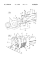
- FIG. 1 is a side view of a section of a combine harvester having a multicylinder threshing mechanism, a feed drum and a following axial separator incorporating an intake zone in accordance with the invention.
- FIG. 2 is a top view of an axial separator incorporating the intake zone in accordance with the invention but without the upper casing for this zone.
- FIG. 3 is a perspective view of the intake zone in accordance with the invention based on the example of an axial separator.
- FIG. 4 is a schematic illustration of the cross-section of the rotor and its cladding at the beginning of the intake zone along the section line IV--IV in FIG. 1.
- FIG. 5 is a schematic illustration of the cross-section of the rotor and its cladding at the end of the intake zone along the section line V--V in FIG. 1.
- FIG. 1 A partial view of a not particularly described combine harvester 1 illustrated in FIG. 1 shows that it is equipped with a likewise not particularly described two cylinder tangential threshing mechanism 2, a feed drum 3 and a following axial separator 4 incorporating an intake zone 4a in accordance with an embodiment of the invention.
- Any tangential threshing mechanism of the single or multi-cylinder type may be employed in place of the two cylinder tangential threshing mechanism 2 used in this embodiment.
- the axial separator 4 is fixed, in a not particularly described manner, in the combine harvester such that its position relative to the feed drum 3 cannot be altered.
- the intake zone 4a (FIG. 2) of the axial separator 4 is comprised by a rotor inlet 5 of a separator rotor 6 in accordance with an embodiment of the invention and of a unique cladding 7 for the intake zone, both of which will be described in detail hereinafter.
- a core tube 8 of the separator rotor 6 has a cylindrical cross-section.
- the intake zone 4a it is provided with an extension piece 9 in the form of a frustum of a cone whose greater diameter, at the end of the intake zone 4a, corresponds to that of the core tube 8.
- Two helical base members 10, which are relatively displaced through 180°, are welded to the peripheral surface of the truncated cone shaped extension piece 9. The height of these members decreases in proportion to the increase in radius of the extension piece 9. This creates a cylindrical start for the rotor having an envelope diameter which is no greater than that of the remainder of the separator rotor 6.
- helical wear-resistant pieces 11 are bolted onto the helical base members 10. Their height decreases over the length from the start to the end of the base members 10 and this thereby creates the conically tapering shape of the rotor inlet 5 in the direction in which the material flows.
- the cladding 7 for the intake zone (FIG. 3) is comprised by upper and lower casings 12, 13 in accordance with an embodiment of the invention, which will be described in detail hereinbelow, together with a material pick up head 14 and an adapting flange 15.
- the upper casing 12 is designed such that, at the start of the intake zone 4a, it has a circular cross-section which is aligned with the upper half-shell of the cladding for a separator zone 16 (FIG. 4). From there, its cross-section continuously alters until, at the end of the intake zone 5, it matches the eccentric cross-section of the upper half-shell of the cladding for the separator zone 16 (FIG. 5).
- the semi-circular front end of the upper casing 12 is welded to the material pick up head 14 whilst its eccentric rear end is welded to the adapting flange 15.
- the lower casing 13 is semi-circular and its cross-section decreases conically towards an end 20 of the intake zone.
- This casing consists of thin-walled plates incorporating regularly or irregularly dispersed openings which may be of any shape in addition to the type of hole 17 shown in this embodiment.
- the lower casing 13 is hung in not-illustrated grooves in the upper casing 12 by means of not-illustrated chip-like elements and releasably connected over the remainder of its periphery to the material pick up head 14, the adapting flange 15 and the other side edge of the upper casing 12, although this too is not illustrated.
- the inner surface of the lower casing facing the rotor inlet 5 is provided with guide rails 19 although these will not be described in detail.
- the upper casing 12 of the intake zone 4a is provided with a plurality of guide rails 18 extending helically in the direction of material flow on the inner surface thereof facing the rotor inlet 5.
- the height of these rails increases towards the end 20 of the intake zone by the same amount as the reduction in radius of the envelope of the conical rotor inlet 5.
- the cladding 7 for the intake zone is releasably connected via the adapting flange 15 to the cladding around the separator zone 16. Moreover, the material pick up head 14 of the intake zone cladding 7 is reinforced in not particularly described manner so as to provide the front mounting for the separator rotor 6 through the intermediary of a retaining stay 21 releasably attached to the upper part thereof.
- FIGS. 1 to 3 is concerned with an advantageous design for the intake zone of an axial-flow threshing and separating assembly or of an axial separator in a combine harvester.
- the concept described hereinabove may be transferred without difficulty to systems in other fields of application by the skilled person.
Landscapes
- Life Sciences & Earth Sciences (AREA)
- Environmental Sciences (AREA)
- Threshing Machine Elements (AREA)
Abstract
The present invention describes an intake zone (4a) for an axial separator (4) consisting of a rotor (6) that is configured as a cone in its front area, is tapered in the direction of the flow of materials and has a sleeve (12, 13, 16) or an intake zone for a similar axial flow threshing and separating device having at least one similar separating rotor (6) arranged downstream from a single or multi-cylinder threshing machine with a feed cylinder (3) connected thereto. The upper sleeve (12) of the intake zone (4a) has a semi-circular cross-section at the beginning of the rotor intake continuously running as far as the end of the intake zone (20) into an eccentric cross-section corresponding to the cross-section of the remaining upper sleeve. The spiral-shaped base bodies (10) of the cylindrical rotor intake (5) are staggered in relation to each other and are provided with interchangeable spiral-shaped wearing parts, the height of which decreases in the direction of the end of the intake zone (20) in such a way that a conical enveloping surface arises.
Description
This application is a continuation of PCT Application No. PCT/EP98/03102 filed May 26, 1998 and which named the United States as a designated country.
The present invention relates to a conically tapering intake zone having a continuously matched intake housing for an axial-flow threshing and dividing mechanism, or, for an axial separator. In a combine harvester, at least one such axial separator is arranged downstream of a single or multi-cylinder type tangential threshing mechanism and its feed drum.
Problems, relating to the transportation of materials in the transfer zone between the tangentially functioning feed rake shaft i.e. the above mentioned single or multi-cylinder threshing mechanism with its attached feed drum, and the axial onward path extending at right angles thereto in the known axial-flow threshing and dividing assemblies or axial separators, have led to very many differing designs for the intake zones to the rotors and the claddings thereof.
In the case of parallel axis, double rotors having a cylindrical intake zone, it is known from EP 0 244 862 to provide trapezoidal and conical extensions to the upper half-shell of the rotor cladding in the intake zone. In order to ensure trouble-free pick up and distribution of the tangentially supplied material in the intake zone of the rotors, these trapezoidal or conical extensions are designed such that they extend over both rotors at the start of the intake zone and then, at the end thereof, taper such that the edge-sections of these extensions are aligned with the remainder of the rotor cladding when viewed from above and coincide centrally between the two rotors at the end of the intake zone. Trouble-free pick up of the material in the intake zone is thereby achieved but only at the expense of a very complicated and hence cost intensive manufacturing process for the rotor cladding. Moreover, due to the large amount of space in the upper part of the intake zone between the feeder members on the rotors and the rotor cladding and as a result of a lack of conveying or advancing mechanisms, it is necessary to have an appropriately high bulk factor of material in this upper region so as to ensure that the material will be transported properly even though it is beyond the effective range of the pusher members.
In addition, in the case of axial-flow type combine harvesters, it is known to use one and two rotor assemblies which are provided at their front ends with conically tapering wing-like or helical elements which are encased by conical intake housings. This form of construction is intended to provide positive pick up and distribution of the material as well as a reduction in the breadth of the stream of material issuing from the feed rake shaft to match the diameter of the rotor. However, this type of axial-flow combine harvester suffers from the substantial disadvantage of the step-like transition between the intake zone and the threshing and dividing zone in the upper or lower parts of the rotor cladding. The stratification processes occurring in these regions lead to an increase in the power requirements.
In regard to the enlarged spacing between the threshing and dividing rotors of the axial-flow combine harvester and the upper half-shells of the rotor claddings, it is known from EP 0 631 716 to employ spacer rails which are inserted between the upper and lower half-shells. Apart from the high assembly costs, the disadvantages of this concept lie in the positioning of the separate spacer rails, which are of different shapes in the threshing and dividing zones, in the stepped inner wall of the rotor cladding where the conditions are particularly unfavorable as described above.
An object of the invention is to provide a design for the intake zone of axial-flow threshing and dividing rotors or of axial separators which adds to the full functional capabilities thereof.
In accordance with the invention, this object is achieved in that the crosssection of the single or multi-part upper casing for the intake zone is semi-circular at the beginning of the inlet to the rotor and changes over the length of the zone so that at the end thereof it then corresponds to the eccentric cross-section of the remainder of the upper casing. The result of this arrangement is that the compressed material is separated in the upper, non-separating space between the rotor and the cladding, and the friction between the material and the upper casing of the intake zone is reduced. Moreover, the stepless transition from the intake zone to the threshing or dividing zone prevents the unfavorable, highly energetic stratification and turbulence effects.
The helical pusher elements at the beginning of the conical rotor have a two-part construction so as to enable the rotor to be removed from the rear wall of the combine harvester opposite the feed mechanisms with little effort. The helical base members connected to the rotor are designed such that a cylindrical rotor core is formed at the beginning of the rotor, the diameter of the envelope of this cylinder being no greater than that of the remainder of the rotor. The helical base members are provided with interchangeable wear-resistant elements that are also in the form of a helix whose height reduces from the start of the rotor up to the end of the intake zone. This form of construction results in the initial part of the rotor having a conical shape which tapers in the direction of flow of the materials and thereby improves the pick up of these materials.
In order to improve the transportation of the materials in the intake zone of a threshing and dividing rotor or of an axial separator rotor, the upper section of the cladding for the intake zone is provided with a plurality of guide rails on its inner surface, said rails extending helically in the direction of flow of the materials and the height thereof increasing by the same amount as the diameter of the envelope of the initial part of the rotor decreases so that the spacing between the upper edges of the guide rails and the wear-resistant elements remains constant and low throughout the whole of the upper section of the intake zone. In known manner, the inner face of the lower cladding for the intake zone is also provided with guide rails for maintaining a constant flow of materials, the height of these rails remaining constant however.
The lower unhingeable section of the casing for the intake zone is provided with openings for separating loose grains dispersed in the layer of material whilst they are still in the intake zone so as to thereby reduce the load, in dependence on the construction of the rotor, in the following threshing and dividing zone.
An embodiment of the invention will be explained in detail hereinafter with the help of the drawings wherein:
FIG. 1 is a side view of a section of a combine harvester having a multicylinder threshing mechanism, a feed drum and a following axial separator incorporating an intake zone in accordance with the invention.
FIG. 2 is a top view of an axial separator incorporating the intake zone in accordance with the invention but without the upper casing for this zone.
FIG. 3 is a perspective view of the intake zone in accordance with the invention based on the example of an axial separator.
FIG. 4 is a schematic illustration of the cross-section of the rotor and its cladding at the beginning of the intake zone along the section line IV--IV in FIG. 1.
FIG. 5 is a schematic illustration of the cross-section of the rotor and its cladding at the end of the intake zone along the section line V--V in FIG. 1.
A partial view of a not particularly described combine harvester 1 illustrated in FIG. 1 shows that it is equipped with a likewise not particularly described two cylinder tangential threshing mechanism 2, a feed drum 3 and a following axial separator 4 incorporating an intake zone 4a in accordance with an embodiment of the invention. Any tangential threshing mechanism of the single or multi-cylinder type may be employed in place of the two cylinder tangential threshing mechanism 2 used in this embodiment.
The axial separator 4 is fixed, in a not particularly described manner, in the combine harvester such that its position relative to the feed drum 3 cannot be altered.
The intake zone 4a (FIG. 2) of the axial separator 4 is comprised by a rotor inlet 5 of a separator rotor 6 in accordance with an embodiment of the invention and of a unique cladding 7 for the intake zone, both of which will be described in detail hereinafter.
A core tube 8 of the separator rotor 6 has a cylindrical cross-section. In the intake zone 4a, it is provided with an extension piece 9 in the form of a frustum of a cone whose greater diameter, at the end of the intake zone 4a, corresponds to that of the core tube 8. Two helical base members 10, which are relatively displaced through 180°, are welded to the peripheral surface of the truncated cone shaped extension piece 9. The height of these members decreases in proportion to the increase in radius of the extension piece 9. This creates a cylindrical start for the rotor having an envelope diameter which is no greater than that of the remainder of the separator rotor 6. In accordance with an embodiment of the invention, helical wear-resistant pieces 11 are bolted onto the helical base members 10. Their height decreases over the length from the start to the end of the base members 10 and this thereby creates the conically tapering shape of the rotor inlet 5 in the direction in which the material flows.
The cladding 7 for the intake zone (FIG. 3) is comprised by upper and lower casings 12, 13 in accordance with an embodiment of the invention, which will be described in detail hereinbelow, together with a material pick up head 14 and an adapting flange 15. The upper casing 12 is designed such that, at the start of the intake zone 4a, it has a circular cross-section which is aligned with the upper half-shell of the cladding for a separator zone 16 (FIG. 4). From there, its cross-section continuously alters until, at the end of the intake zone 5, it matches the eccentric cross-section of the upper half-shell of the cladding for the separator zone 16 (FIG. 5). The semi-circular front end of the upper casing 12 is welded to the material pick up head 14 whilst its eccentric rear end is welded to the adapting flange 15.
The lower casing 13 is semi-circular and its cross-section decreases conically towards an end 20 of the intake zone. This casing consists of thin-walled plates incorporating regularly or irregularly dispersed openings which may be of any shape in addition to the type of hole 17 shown in this embodiment. The lower casing 13 is hung in not-illustrated grooves in the upper casing 12 by means of not-illustrated chip-like elements and releasably connected over the remainder of its periphery to the material pick up head 14, the adapting flange 15 and the other side edge of the upper casing 12, although this too is not illustrated. In known manner, the inner surface of the lower casing facing the rotor inlet 5 is provided with guide rails 19 although these will not be described in detail.
The upper casing 12 of the intake zone 4a is provided with a plurality of guide rails 18 extending helically in the direction of material flow on the inner surface thereof facing the rotor inlet 5. The height of these rails increases towards the end 20 of the intake zone by the same amount as the reduction in radius of the envelope of the conical rotor inlet 5.
The cladding 7 for the intake zone is releasably connected via the adapting flange 15 to the cladding around the separator zone 16. Moreover, the material pick up head 14 of the intake zone cladding 7 is reinforced in not particularly described manner so as to provide the front mounting for the separator rotor 6 through the intermediary of a retaining stay 21 releasably attached to the upper part thereof.
The embodiment illustrated in FIGS. 1 to 3 is concerned with an advantageous design for the intake zone of an axial-flow threshing and separating assembly or of an axial separator in a combine harvester. However, the concept described hereinabove may be transferred without difficulty to systems in other fields of application by the skilled person.
Claims (7)
1. An axial separator comprising a rotor having an inlet and a casing having an intake zone and a downstream zone, the intake zone being conical at an inlet thereof and convering in a direction of flow of material, wherein the casing of the downstream zone has an eccentric cross-section, and wherein a cross-section of the casing (12) for the intake zone (7) is penerally circular at the inlet (5) of the rotor and converges to a downstream end (20) of the intake zone adjacent the downstream zone where the cross-section of the in1ake zone corresponds to the eccentric cross-section of the casing of the downstream zone.
2. An axial separator having an intakc zone as in claim 1, including mutually displaced helical base members (10) of the rotor inlet (5), the base members being provided with interchangeable wear-resistant helical parts whose height reduces toward the downsteam end (20) of the intake zone to produce a conical envelope surface.
3. An axial separator having an intake zone as in claim 1, including a lower semi-includes thin-walled plates.
4. An axial segarator haing an intake zone as in claim 3, wherein the lower section (13) of the casing for the intake zone (4a) is provided with cut-outs at regular or irregular intervals.
5. An axial separator having an intake zone as in claim 4, wherein thes cut-uuts have different shapes.
6. An-axial separator having an intake zone as in claim 1, including an upper casing (12) for the intake zone (4a), the upper casing being provided with a plurality of guide rails (18) on an inner surface facing the rotor inlet (5), said rails extending helically in the direction of flow of the material and the height thereof increasing toward the downstream end (20) of the intake zone by the same amount as the radius of the envelope of the conical rotor inlet (5) decreases.
7. An axial separator having an intake zone mild a downstream zone and comprising a rotor and a sing having upper and lower parts, wherein said rotor is conical at a front end thereof and converges in a direction of flow of material, and wherein a cross-section of the upper part of the casing for the intake zone is semicircular at the inlet of the rotor and converges to a downstream end of the intake zone where the cross-section of the upper part of the casing for the intake zone corresponds to an eccentric cross-section of the upper casing of the downstream zone.
Applications Claiming Priority (3)
| Application Number | Priority Date | Filing Date | Title |
|---|---|---|---|
| DE19722079 | 1997-05-27 | ||
| DE19722079A DE19722079A1 (en) | 1997-05-27 | 1997-05-27 | Feed area of an axial separator |
| PCT/EP1998/003102 WO1998053662A1 (en) | 1997-05-27 | 1998-05-26 | Insert zone for axial separator |
Related Parent Applications (1)
| Application Number | Title | Priority Date | Filing Date |
|---|---|---|---|
| PCT/EP1998/003102 Continuation WO1998053662A1 (en) | 1997-05-27 | 1998-05-26 | Insert zone for axial separator |
Publications (1)
| Publication Number | Publication Date |
|---|---|
| US6129629A true US6129629A (en) | 2000-10-10 |
Family
ID=26036870
Family Applications (1)
| Application Number | Title | Priority Date | Filing Date |
|---|---|---|---|
| US09/448,788 Expired - Lifetime US6129629A (en) | 1997-05-27 | 1999-11-24 | Intake zone for axial separator |
Country Status (1)
| Country | Link |
|---|---|
| US (1) | US6129629A (en) |
Cited By (25)
| Publication number | Priority date | Publication date | Assignee | Title |
|---|---|---|---|---|
| US6257977B1 (en) | 1999-08-20 | 2001-07-10 | Deere & Company | Rotary combine having a rotor axis divergent from a rotor housing axis |
| US6367611B1 (en) * | 2000-08-22 | 2002-04-09 | General Electric Company | Part feeding system |
| US6468152B2 (en) * | 2001-03-02 | 2002-10-22 | Deere & Company | Rotary combine having a frusto-conical rotor housing |
| US6517431B2 (en) * | 2000-04-19 | 2003-02-11 | Claas Selbstfahrende Erntemaschinen Gmbh | Combine harvester having a transfer zone with side panels |
| US6544118B2 (en) * | 2000-04-19 | 2003-04-08 | Claas Selbstfahrende Erntemaschinen Gmbh | Self-propelled combine harvester having asymmetric transaction housings |
| US6688970B2 (en) | 2001-11-15 | 2004-02-10 | Case Corporation | Combine threshing rotor front bearing and inlet section with anti-wind geometry |
| US6780102B2 (en) * | 2001-03-19 | 2004-08-24 | Claas Selbstfahrende Erntemaschinen Gmbh | Transfer mechanism for feeding harvested crop to a separation unit |
| US6830512B2 (en) * | 2002-07-19 | 2004-12-14 | Cnh America Llc | Shroud for the infeed impeller of a rotary combine |
| US20050020329A1 (en) * | 2003-07-21 | 2005-01-27 | Ricketts Jonathan E. | Threshing rotor inlet flight extension |
| RU2272399C2 (en) * | 2004-04-08 | 2006-03-27 | Евгений Васильевич Лаптев | Grain combine |
| US20060223598A1 (en) * | 2005-04-01 | 2006-10-05 | Cnh America Llc | Anti-wind wiper with adjustable extension |
| US20120064955A1 (en) * | 2010-09-09 | 2012-03-15 | Thomas Barrelmeyer | Separating unit for a combine harvester |
| US20120100898A1 (en) * | 2009-01-27 | 2012-04-26 | Agco A/S | Combine harvesters |
| EP2574231A1 (en) * | 2011-09-30 | 2013-04-03 | CLAAS Selbstfahrende Erntemaschinen GmbH | Combine harvester |
| CN104365292A (en) * | 2007-01-11 | 2015-02-25 | 株式会社久保田 | Threshing device |
| US20160007536A1 (en) * | 2014-07-10 | 2016-01-14 | Claas Selbstfahrende Erntemaschinen Gmbh | Inlet head housing |
| US9807937B2 (en) * | 2015-07-16 | 2017-11-07 | Cnh Industrial America Llc | Agricultural harvester with improved rotor transition geometry |
| US10123485B2 (en) * | 2015-10-16 | 2018-11-13 | Cnh Industrial America Llc | Tapered vane for agricultural harvester transition cone |
| US10159192B2 (en) * | 2015-09-17 | 2018-12-25 | Cone Guard, Llc | Transition cone liner for a farm combine |
| WO2019178466A1 (en) * | 2018-03-15 | 2019-09-19 | Cnh Industrial America Llc | Tangential feeding to a threshing rotor |
| US10448575B1 (en) | 2018-04-10 | 2019-10-22 | Unverferth Manufacturing Company, Inc. | Auger flight extension for a farm implement |
| US20210161074A1 (en) * | 2017-12-26 | 2021-06-03 | Amadas Industries, Inc. | Threshing/Separating Device Having Tined Accelerator and/or Axial Rotor System |
| US11382274B2 (en) * | 2019-04-29 | 2022-07-12 | Claas Selbstfahrende Erntemaschinen Gmbh | Separation arrangement for a combine harvester |
| US20230210055A1 (en) * | 2021-12-30 | 2023-07-06 | Cnh Industrial America Llc | Variable cross-section vane for transition cone in combine harvester |
| EP4338580A1 (en) * | 2022-09-13 | 2024-03-20 | CLAAS Selbstfahrende Erntemaschinen GmbH | Self-propelled combine harvester |
Citations (11)
| Publication number | Priority date | Publication date | Assignee | Title |
|---|---|---|---|---|
| DE2048892A1 (en) * | 1969-10-08 | 1971-04-22 | International Harvester Co , Chica go, 111 (V St A) | Combine harvester with threshing device to be passed through by the crop in the Langs river |
| US4148323A (en) * | 1977-11-21 | 1979-04-10 | International Harvester Company | Swept back impeller blade for axial flow rotor |
| US4291709A (en) * | 1980-07-02 | 1981-09-29 | Sperry Corporation | Infeed geometry |
| FR2525429A1 (en) * | 1982-04-21 | 1983-10-28 | Fortschritt Veb K | ENTRY AREA FOR THE THRESHING AND SEPARATION DRUM OF AXIAL FLOW COMBINE HARVESTER |
| US4611605A (en) * | 1984-08-29 | 1986-09-16 | Deere & Company | Axial flow rotary separator |
| EP0244862A1 (en) * | 1986-05-09 | 1987-11-11 | Deere & Company | Harvester threshers |
| US5145462A (en) * | 1991-06-10 | 1992-09-08 | Case Corporation | Infeed assembly for an axial-flow combine |
| US5257959A (en) * | 1991-03-21 | 1993-11-02 | Case Corporation | Door assembly for an axial-flow combine |
| EP0591688A2 (en) * | 1992-09-28 | 1994-04-13 | CLAAS Kommanditgesellschaft auf Aktien | Self-propelled combine |
| EP0631716A1 (en) * | 1993-07-01 | 1995-01-04 | Deere & Company | Axial-flow, thresher-separator device |
| US5688170A (en) * | 1993-07-01 | 1997-11-18 | Deere & Company | Rotary combine having a concentric infeed section and eccentric threshing and separating sections |
-
1999
- 1999-11-24 US US09/448,788 patent/US6129629A/en not_active Expired - Lifetime
Patent Citations (12)
| Publication number | Priority date | Publication date | Assignee | Title |
|---|---|---|---|---|
| DE2048892A1 (en) * | 1969-10-08 | 1971-04-22 | International Harvester Co , Chica go, 111 (V St A) | Combine harvester with threshing device to be passed through by the crop in the Langs river |
| US4148323A (en) * | 1977-11-21 | 1979-04-10 | International Harvester Company | Swept back impeller blade for axial flow rotor |
| US4291709A (en) * | 1980-07-02 | 1981-09-29 | Sperry Corporation | Infeed geometry |
| FR2525429A1 (en) * | 1982-04-21 | 1983-10-28 | Fortschritt Veb K | ENTRY AREA FOR THE THRESHING AND SEPARATION DRUM OF AXIAL FLOW COMBINE HARVESTER |
| US4611605A (en) * | 1984-08-29 | 1986-09-16 | Deere & Company | Axial flow rotary separator |
| EP0244862A1 (en) * | 1986-05-09 | 1987-11-11 | Deere & Company | Harvester threshers |
| US5257959A (en) * | 1991-03-21 | 1993-11-02 | Case Corporation | Door assembly for an axial-flow combine |
| US5145462A (en) * | 1991-06-10 | 1992-09-08 | Case Corporation | Infeed assembly for an axial-flow combine |
| EP0591688A2 (en) * | 1992-09-28 | 1994-04-13 | CLAAS Kommanditgesellschaft auf Aktien | Self-propelled combine |
| EP0631716A1 (en) * | 1993-07-01 | 1995-01-04 | Deere & Company | Axial-flow, thresher-separator device |
| US5445563A (en) * | 1993-07-01 | 1995-08-29 | Deere & Company | Axial flow combine having a concentric threshing section and an eccentric separating section |
| US5688170A (en) * | 1993-07-01 | 1997-11-18 | Deere & Company | Rotary combine having a concentric infeed section and eccentric threshing and separating sections |
Cited By (38)
| Publication number | Priority date | Publication date | Assignee | Title |
|---|---|---|---|---|
| US6257977B1 (en) | 1999-08-20 | 2001-07-10 | Deere & Company | Rotary combine having a rotor axis divergent from a rotor housing axis |
| US6517431B2 (en) * | 2000-04-19 | 2003-02-11 | Claas Selbstfahrende Erntemaschinen Gmbh | Combine harvester having a transfer zone with side panels |
| US6544118B2 (en) * | 2000-04-19 | 2003-04-08 | Claas Selbstfahrende Erntemaschinen Gmbh | Self-propelled combine harvester having asymmetric transaction housings |
| US6367611B1 (en) * | 2000-08-22 | 2002-04-09 | General Electric Company | Part feeding system |
| US6468152B2 (en) * | 2001-03-02 | 2002-10-22 | Deere & Company | Rotary combine having a frusto-conical rotor housing |
| US6780102B2 (en) * | 2001-03-19 | 2004-08-24 | Claas Selbstfahrende Erntemaschinen Gmbh | Transfer mechanism for feeding harvested crop to a separation unit |
| US6688970B2 (en) | 2001-11-15 | 2004-02-10 | Case Corporation | Combine threshing rotor front bearing and inlet section with anti-wind geometry |
| US6830512B2 (en) * | 2002-07-19 | 2004-12-14 | Cnh America Llc | Shroud for the infeed impeller of a rotary combine |
| US20050020329A1 (en) * | 2003-07-21 | 2005-01-27 | Ricketts Jonathan E. | Threshing rotor inlet flight extension |
| US6908378B2 (en) * | 2003-07-21 | 2005-06-21 | Cnh America Llc | Threshing rotor inlet flight extension |
| RU2272399C2 (en) * | 2004-04-08 | 2006-03-27 | Евгений Васильевич Лаптев | Grain combine |
| US20060223598A1 (en) * | 2005-04-01 | 2006-10-05 | Cnh America Llc | Anti-wind wiper with adjustable extension |
| US20070004478A1 (en) * | 2005-04-01 | 2007-01-04 | Tanis Dale R | Method of adjusting an anti-wind wiper assembly |
| US7223167B2 (en) | 2005-04-01 | 2007-05-29 | Cnh America Llc | Anti-wind wiper with adjustable extension |
| CN104365292A (en) * | 2007-01-11 | 2015-02-25 | 株式会社久保田 | Threshing device |
| US8556690B2 (en) * | 2009-01-27 | 2013-10-15 | Agco A/S | Feed beater directional vanes and scraper vanes |
| US20120100898A1 (en) * | 2009-01-27 | 2012-04-26 | Agco A/S | Combine harvesters |
| US20120064955A1 (en) * | 2010-09-09 | 2012-03-15 | Thomas Barrelmeyer | Separating unit for a combine harvester |
| US8251787B2 (en) * | 2010-09-09 | 2012-08-28 | Claas Selbstfahrende Erntemaschinen Gmbh | Separating unit for a combine harvester |
| EP2574231A1 (en) * | 2011-09-30 | 2013-04-03 | CLAAS Selbstfahrende Erntemaschinen GmbH | Combine harvester |
| US20160007536A1 (en) * | 2014-07-10 | 2016-01-14 | Claas Selbstfahrende Erntemaschinen Gmbh | Inlet head housing |
| US9706714B2 (en) * | 2014-07-10 | 2017-07-18 | Claas Selbstfahrende Erntemaschinen Gmbh | Inlet head housing for an axial separating device |
| US9807937B2 (en) * | 2015-07-16 | 2017-11-07 | Cnh Industrial America Llc | Agricultural harvester with improved rotor transition geometry |
| US10159192B2 (en) * | 2015-09-17 | 2018-12-25 | Cone Guard, Llc | Transition cone liner for a farm combine |
| US11083136B2 (en) * | 2015-10-16 | 2021-08-10 | Cnh Industrial America Llc | Tapered vane for agricultural harvester transition cone |
| US10123485B2 (en) * | 2015-10-16 | 2018-11-13 | Cnh Industrial America Llc | Tapered vane for agricultural harvester transition cone |
| US11102930B2 (en) * | 2017-12-26 | 2021-08-31 | Amadas Industries, Inc. | Threshing/separating device having tined accelerator and/or axial rotor arrangement |
| US20210161074A1 (en) * | 2017-12-26 | 2021-06-03 | Amadas Industries, Inc. | Threshing/Separating Device Having Tined Accelerator and/or Axial Rotor System |
| US12324376B2 (en) * | 2017-12-26 | 2025-06-10 | Amadas Industries, Inc. | Threshing/separating device having tined accelerator and/or axial rotor system |
| US20200404849A1 (en) * | 2018-03-15 | 2020-12-31 | Cnh Industrial America Llc | Tangential Feeding to a Threshing Rotor |
| WO2019178466A1 (en) * | 2018-03-15 | 2019-09-19 | Cnh Industrial America Llc | Tangential feeding to a threshing rotor |
| US11812701B2 (en) * | 2018-03-15 | 2023-11-14 | Cnh Industrial America Llc | Tangential feeding to a threshing rotor |
| US10874055B2 (en) | 2018-04-10 | 2020-12-29 | Unverferth Manufacturing Company, Inc. | Auger flight extension for a farm implement |
| US10448575B1 (en) | 2018-04-10 | 2019-10-22 | Unverferth Manufacturing Company, Inc. | Auger flight extension for a farm implement |
| US11382274B2 (en) * | 2019-04-29 | 2022-07-12 | Claas Selbstfahrende Erntemaschinen Gmbh | Separation arrangement for a combine harvester |
| US20230210055A1 (en) * | 2021-12-30 | 2023-07-06 | Cnh Industrial America Llc | Variable cross-section vane for transition cone in combine harvester |
| US12369529B2 (en) * | 2021-12-30 | 2025-07-29 | Cnh Industrial America Llc | Variable cross-section vane for transition cone in combine harvester |
| EP4338580A1 (en) * | 2022-09-13 | 2024-03-20 | CLAAS Selbstfahrende Erntemaschinen GmbH | Self-propelled combine harvester |
Similar Documents
| Publication | Publication Date | Title |
|---|---|---|
| US6129629A (en) | Intake zone for axial separator | |
| CA1107168A (en) | Rotor for an axial flow combine | |
| US8118652B2 (en) | Beater and feed mechanism for a combine harvester | |
| ES8303007A1 (en) | Threshing and separating drum for an axial-flow combine harvester. | |
| CA1246958A (en) | Rotor for an axial flow rotary separator | |
| US7749054B2 (en) | Modular separator element for a threshing system | |
| US20100173684A1 (en) | Combines | |
| EP2200914B1 (en) | Auger conveyors | |
| US5919086A (en) | Combine rotor and method | |
| AU2003226930B2 (en) | A decanter centrifuge | |
| US8181570B2 (en) | Plug screw feeder for feeding cellulose pulp/chips | |
| GB2163635A (en) | Combine harvester | |
| RU98113930A (en) | DECANTING CENTRIFUGE | |
| WO1997022411A1 (en) | A decanter centrifuge | |
| CA1206920A (en) | Vortex cleaner | |
| NZ535207A (en) | Decanter centrifuge with wear reinforcement inlet | |
| FI110768B (en) | Tube feeder device | |
| GB2266287A (en) | Auger conveyor | |
| CA2206854A1 (en) | Auger assembly for conveying granular material | |
| DE69007585T2 (en) | Sub-caliber bullet with a bullet core, a sabot and a jacket. | |
| ES480098A1 (en) | Feed rotor for an axial flow rotary combine | |
| FI67590C (en) | VIRVELRENARE | |
| RU2201065C2 (en) | Receiving part of axial separator | |
| EP1122356A3 (en) | Refiner | |
| CA1201620A (en) | Bark processing machine |
Legal Events
| Date | Code | Title | Description |
|---|---|---|---|
| AS | Assignment |
Owner name: CLAAS SELBSTFAHRENDE ERNTEMASCHINEN GMBH, GERMANY Free format text: ASSIGNMENT OF ASSIGNORS INTEREST;ASSIGNORS:DAMMANN, MARTIN;HEIDJANN, FRANZ;KUHN, BODO;REEL/FRAME:010430/0346;SIGNING DATES FROM 19991020 TO 19991102 |
|
| STCF | Information on status: patent grant |
Free format text: PATENTED CASE |
|
| FEPP | Fee payment procedure |
Free format text: PAYOR NUMBER ASSIGNED (ORIGINAL EVENT CODE: ASPN); ENTITY STATUS OF PATENT OWNER: LARGE ENTITY |
|
| CC | Certificate of correction | ||
| FPAY | Fee payment |
Year of fee payment: 4 |
|
| FPAY | Fee payment |
Year of fee payment: 8 |
|
| FPAY | Fee payment |
Year of fee payment: 12 |