US6125548A - Bottle rack - Google Patents
Bottle rack Download PDFInfo
- Publication number
- US6125548A US6125548A US09/513,094 US51309400A US6125548A US 6125548 A US6125548 A US 6125548A US 51309400 A US51309400 A US 51309400A US 6125548 A US6125548 A US 6125548A
- Authority
- US
- United States
- Prior art keywords
- tray
- pegs
- upper face
- peg
- article
- Prior art date
- Legal status (The legal status is an assumption and is not a legal conclusion. Google has not performed a legal analysis and makes no representation as to the accuracy of the status listed.)
- Ceased
Links
Images
Classifications
-
- F—MECHANICAL ENGINEERING; LIGHTING; HEATING; WEAPONS; BLASTING
- F26—DRYING
- F26B—DRYING SOLID MATERIALS OR OBJECTS BY REMOVING LIQUID THEREFROM
- F26B25/00—Details of general application not covered by group F26B21/00 or F26B23/00
- F26B25/06—Chambers, containers, or receptacles
- F26B25/14—Chambers, containers, receptacles of simple construction
- F26B25/18—Chambers, containers, receptacles of simple construction mainly open, e.g. dish, tray, pan, rack
-
- A—HUMAN NECESSITIES
- A47—FURNITURE; DOMESTIC ARTICLES OR APPLIANCES; COFFEE MILLS; SPICE MILLS; SUCTION CLEANERS IN GENERAL
- A47L—DOMESTIC WASHING OR CLEANING; SUCTION CLEANERS IN GENERAL
- A47L19/00—Drying devices for crockery or table-ware, e.g. tea-cloths
- A47L19/04—Crockery baskets; Draining-racks
Definitions
- This invention pertains generally to the field of infant feeding and care. More specifically, this invention relates to an improved apparatus for storing and drying infant nursing bottles, nipples and rings that is more hygienic, efficient and attractive than articles that are presently available for similar purposes, and that is more convenient to store for consumers.
- bottles and nipples should be thoroughly scrubbed, then sterilized by immersion in boiling water between uses.
- baby bottles and components thereof which typically include rings, nipples, hoods and disks, must be washed with an effective detergent and dried in a location that is separated from dirty water or potential contaminants prior to storage for future use.
- Drying racks for holding baby bottles, rings and nipples after washing are commercially available.
- such products are sold by Safety 1 st , Inc. as a "Bottle and Nipple Drying Rack,” and by Mommy's Helper, Inc. as a “Drain 'N Dry.” Both of these products are characterized by a plastic tray that has a number of socket recesses defined in a top face thereof. Plastic pegs are provided that are insertable into the socket recesses. Some of the plastic pegs are relatively long, for supporting a bottle, while others are shorter, for supporting nipples, rings and caps. Neither these products nor any other drying rack of which the inventors are aware have any way of storing the disks of a baby bottle in a sanitary location after washing.
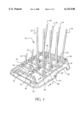
- FIG. 1 is a perspective view of an apparatus that is constructed according to a preferred embodiment of the invention, shown in an operative position;
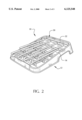
- FIG. 2 is a perspective view of the apparatus of FIG. 1, shown in a storage position;
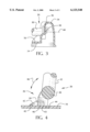
- FIG. 3 is a cross-sectional view taken along lines 3--3 in FIG. 1;
- FIG. 4 is a cross-sectional view taken along lines 4--4 in FIG. 1.
- an apparatus 10 for drying and storing an article, such as a baby bottle, after washing and rinsing includes a tray 12 having a bottom face 14 (viewable in FIG. 3) that is adapted to be supported by an underlying surface such as a countertop. Tray 12 further has an upper face 16, as may be seen in FIGS. 1-4. Tray 12 is further configured to have a number of cutout/grip areas 58 defined in sides thereof, as may best be seen in FIG. 1.
- cutout area 58 The purpose of the cutout area 58 is to permit a consumer to more easily lift the apparatus 10 during use, as well as to prevent vapor lock from occurring between the apparatus 10 and a smooth underlying surface such as a countertop.
- a cutout area 58 is positioned on each side of the apparatus 10, as well as on the rear end thereof.
- apparatus 10 further includes a plurality of pegs 18 that extend outwardly from the upper face 16 of tray 12.
- pegs 18 are sized and arranged so as to be able to support an article, such as a baby bottle, after washing and rinsing.
- each of the pegs 18 are permanently mounted to the tray 12 in such a manner as to be moveable between a first storage position, which is illustrated in FIG. 2, wherein the entire peg 18 is positioned relatively close to the upper face 16 for storage and packaging, and a second, operative position, illustrated in FIG. 1, wherein the pegs 18 are positioned at a large angle with respect to the upper surface 16.
- This mounting arrangement is made possible by a permanent mounting structure 20, which is best illustrated in FIGS. 1, 3 and 4, and which will be discussed in greater detail below.
- the permanent mounting structure 20 is constructed in such a way that no standing water may collect at a point where a peg 18 is mounted, thereby minimizing potential for mold and bacterial growth. Permanent mounting structure 20 is further constructed so as to constrain the pegs 18 for movement about only a single axis of rotation.
- apparatus 10 further includes a number of nipple support members 32 that are constructed and arranged to support a nipple portion of a baby bottle after washing and rinsing.
- the nipple support members 32 are, in a manner that is substantially identical to that of the pegs 18, mounted by means of a permanent mounting structure 20 for movement between a first storage position, where the entire nipple support member 32 is positioned relatively close to the upper face 16 for storage and packaging purposes, and a second, operative position where the nipple support member 32 is positioned at a large angle with respect to the upper face 16.
- the mounting structure 20 for the pegs 18 is substantially identical to that of the nipple support members 32.
- the nipple support members 32 have stylized stops 48, which in the preferred embodiment are styled as hearts, mounted thereon for supporting rings or small bottles above the surface of tray 12.
- FIG. 1 it will be seen that in the illustrated embodiment of the invention four pegs 18 are constrained for common, ganged movement in an arc about a common axis of rotation that is created by a first axle 22. Similarly, a second four pegs 18 are mounted for common movement with a second axle 24. Four nipple support members 32 are mounted for common movement about a third axle 28, while a second four nipple support members 32 are mounted for common movement with a fourth axle 30.
- the axles 22, 24, 28, 30 are substantially parallel, and therefore define arcuate paths of movement for the various pegs 18 and nipple support members 32 that are located within substantially parallel planes. This permits the various pegs 18 and nipple support members 32 to move between the first and second positions, as represented by FIGS. 2 and 1, respectively, with a minimum of interference with each other.
- each axle 22, 24, 28, 30 includes a journal 38 that extends through a mounting hole that is defined in a sidewall 36 of an upstanding dam 34 that is formed along the periphery of the upper face 16 of the tray 12.
- This mounting structure 20 is arranged in such a way so as to constrain the axle 22, 24, 28, 30 for movement about an axis of rotation 40, as is shown in FIG. 3.
- Mounting structure 20 by ganging adjacent pegs 18 and adjacent nipple support members 32 together by use of a common axle, thereby imparts lateral stability to the pegs 18 and the nipple support members 32, further deterring any motion other than about the single axis of rotation 40.
- each axle 22, 24, 28, 30 includes at least one locating structure 26, the purpose of which is to lock the respective axle in a rotational position that corresponds to the second operative position shown in FIG. 1.
- first and second axles 22, 24 include two such locating structures 26, while the third and fourth axles 28, 30 which support the shorter nipple support members 32, are equipped with but one locating structure 26.
- the construction of the locating structures 26, however, is uniform throughout the four axles 22, 24, 28, 30. As may be seen in FIG.
- locating structure 26 includes a cam member 43 having a lower surface 44 that is constructed and arranged to bear against the upper face 16 of tray 12, and a forward surface 46 that is constructed and arranged to come into contact with a rear surface 44 of a cam stop 42 that projects upwardly and is unitary with the upper face 16 of tray 12.
- FIG. 1 and FIG. 4 both depict the locking structure 26 in the second, operative position. The path between the first and second positions is indicated in FIG. 4 by arrow 46.
- the nipple support member 32 is prevented from bending backwardly in the direction away from the first storage position by contact of the forward surface 46 of cam member 43 with the rear surface 44 of cam stop 42.
- a user will push the nipple support member 32 in the desired direction. Initially, this movement will be deterred by the contact of the lower surface 44 and the leading edge of the lower surface with the upper face 16 of tray 12. Once the leading edge 45 has cleared the upper face, however, the nipple support member 32 will easily fold down into the position that is shown in FIG. 2.
- apparatus 10 further includes a disc holding system 50 for holding baby bottle discs in a location that is isolated from areas of the tray 12 in which liquid may collect.
- disc holding system 50 includes an upstanding boss member 52 that projects upwardly from the upper face 16 of tray 12 and has a plurality of disc receiving slots 54 defined therein. Boss member 52 and slots 54 are raised with respect to an underlying reservoir 56 that is located in the forward portion of tray 12.
- the reservoir space also acts as a finger space area for a user to get his/her fingers beneath the disc members for lifting them out after drying.
Abstract
An apparatus for drying and storing an article, such as a baby bottle, after washing and rinsing includes a tray having a bottom face that is adapted to be supported by an underlying surface such as a counter-top, and an upper face. A plurality of pegs extend out from the upper face, and each peg is sized and arranged so as to be able to support an article, such as a baby bottle, after washing and rinsing. Each peg is mounted to the tray in such a manner as to be movable between a first storage position, wherein the entire peg is positioned relatively close to the upper face for storage and packaging, and a second, operative position. This permits the apparatus to be conveniently folded for packaging and storage purposes. Another aspect of the apparatus involves disk holding structure, connected to the upper face of the tray, for holding baby bottle disks in a location that is isolated from areas of the tray in which liquid may collect. This permits baby bottle disks to be dried and stored in a safe manner at a location that is convenient to a location at which baby bottles are being dried.
Description
This is a continuation of Ser. No. 09/113,868, filed on Jul. 10, 1998, U.S. Pat. No. 6,038,784, the disclosure of which is hereby incorporated as if fully set forth herein.
1. Field of the Invention
This invention pertains generally to the field of infant feeding and care. More specifically, this invention relates to an improved apparatus for storing and drying infant nursing bottles, nipples and rings that is more hygienic, efficient and attractive than articles that are presently available for similar purposes, and that is more convenient to store for consumers.
2. Description of the Related Technology
The importance of proper hygiene when handling and cleaning infant feeding equipment such as baby bottles and nursing nipples cannot be overstated. Ideally, bottles and nipples should be thoroughly scrubbed, then sterilized by immersion in boiling water between uses. At the very least, baby bottles and components thereof, which typically include rings, nipples, hoods and disks, must be washed with an effective detergent and dried in a location that is separated from dirty water or potential contaminants prior to storage for future use.
Drying racks for holding baby bottles, rings and nipples after washing are commercially available. For example, such products are sold by Safety 1st, Inc. as a "Bottle and Nipple Drying Rack," and by Mommy's Helper, Inc. as a "Drain 'N Dry." Both of these products are characterized by a plastic tray that has a number of socket recesses defined in a top face thereof. Plastic pegs are provided that are insertable into the socket recesses. Some of the plastic pegs are relatively long, for supporting a bottle, while others are shorter, for supporting nipples, rings and caps. Neither these products nor any other drying rack of which the inventors are aware have any way of storing the disks of a baby bottle in a sanitary location after washing.
Although products of the type described above are quite useful, the lack of disk storage forces conscientious caregivers to separate baby bottle components after washing and rinsing, which can be frustrating and can result in mix-ups between disks that have been washed and unwashed disks. In addition, the sockets that are defined in the top faces of such products can collect water and become points of nucleation for bacteria and mold growth. Furthermore, assembly and disassembly of these products can be laborious, with the need to insert multiple pegs in matching sockets and having to figure out which peg to place in each socket. These products are not convenient to store for a consumer, unless they are completely disassembled. In households that have toddlers, such racks can quickly unbeknownst to the caregiver become a plaything, and pegs can be pulled from the sockets, creating more work and frustration for the caregiver, possibly presenting a risk of injury.
A need exists for a bottle rack that requires minimal or no assembly by the user, that provides a secure and sanitary drying location for all baby bottle components, that minimizes the potential for mold and bacteria growth during use and is easy to store.
Accordingly, it is an object of the invention to provide a bottle rack that requires minimal or no assembly by the user, that provides a secure and sanitary drying location for all baby bottle components, that minimizes the potential for mold and bacteria growth during use and that is easy to store.
In order to achieve the above and other objects of the invention, an apparatus for drying and storing an article, such as a baby bottle includes a tray having a bottom face that is adapted to be supported by an underlying surface such as a counter-top, and an upper face; and a plurality of pegs extending outwardly away from the upper face, each of the pegs being sized and arranged so as to be able to support an article, such as a baby bottle, and wherein the pegs are pivotally mounted to the tray in such a manner as to be movable between a first storage position, wherein said entire peg is positioned relatively close to said upper face for storage and packaging of said apparatus, and a second, operative position, wherein the peg is positioned at a large angle with respect to the upper surface, so as to enable the peg to support an article such as a baby bottle, wherein the apparatus can conveniently be folded for packaging and storage purposes.
These and various other advantages and features of novelty that characterize the invention are pointed out with particularity in the claims annexed hereto and forming a part hereof. However, for a better understanding of the invention, its advantages, and the objects obtained by its use, reference should be made to the drawings which form a further part hereof, and to the accompanying descriptive matter, in which there is illustrated and described a preferred embodiment of the invention.
FIG. 1 is a perspective view of an apparatus that is constructed according to a preferred embodiment of the invention, shown in an operative position;
FIG. 2 is a perspective view of the apparatus of FIG. 1, shown in a storage position;
FIG. 3 is a cross-sectional view taken along lines 3--3 in FIG. 1; and
FIG. 4 is a cross-sectional view taken along lines 4--4 in FIG. 1.
Referring now to the drawings, wherein like reference numerals designate corresponding structure throughout the views, and referring in particular to FIG. 1, an apparatus 10 for drying and storing an article, such as a baby bottle, after washing and rinsing includes a tray 12 having a bottom face 14 (viewable in FIG. 3) that is adapted to be supported by an underlying surface such as a countertop. Tray 12 further has an upper face 16, as may be seen in FIGS. 1-4. Tray 12 is further configured to have a number of cutout/grip areas 58 defined in sides thereof, as may best be seen in FIG. 1. The purpose of the cutout area 58 is to permit a consumer to more easily lift the apparatus 10 during use, as well as to prevent vapor lock from occurring between the apparatus 10 and a smooth underlying surface such as a countertop. In the preferred embodiment, a cutout area 58 is positioned on each side of the apparatus 10, as well as on the rear end thereof.
As is best shown in FIGS. 1 and 2, apparatus 10 further includes a plurality of pegs 18 that extend outwardly from the upper face 16 of tray 12. Each of the pegs 18 is sized and arranged so as to be able to support an article, such as a baby bottle, after washing and rinsing.
According to one important aspect of the invention, each of the pegs 18 are permanently mounted to the tray 12 in such a manner as to be moveable between a first storage position, which is illustrated in FIG. 2, wherein the entire peg 18 is positioned relatively close to the upper face 16 for storage and packaging, and a second, operative position, illustrated in FIG. 1, wherein the pegs 18 are positioned at a large angle with respect to the upper surface 16. This mounting arrangement is made possible by a permanent mounting structure 20, which is best illustrated in FIGS. 1, 3 and 4, and which will be discussed in greater detail below. The permanent mounting structure 20, as will become apparent from the description given below, is constructed in such a way that no standing water may collect at a point where a peg 18 is mounted, thereby minimizing potential for mold and bacterial growth. Permanent mounting structure 20 is further constructed so as to constrain the pegs 18 for movement about only a single axis of rotation.
As may be seen in FIG. 1, apparatus 10 further includes a number of nipple support members 32 that are constructed and arranged to support a nipple portion of a baby bottle after washing and rinsing. The nipple support members 32 are, in a manner that is substantially identical to that of the pegs 18, mounted by means of a permanent mounting structure 20 for movement between a first storage position, where the entire nipple support member 32 is positioned relatively close to the upper face 16 for storage and packaging purposes, and a second, operative position where the nipple support member 32 is positioned at a large angle with respect to the upper face 16. In other words, the mounting structure 20 for the pegs 18 is substantially identical to that of the nipple support members 32. The nipple support members 32 have stylized stops 48, which in the preferred embodiment are styled as hearts, mounted thereon for supporting rings or small bottles above the surface of tray 12.
Looking again to FIG. 1, it will be seen that in the illustrated embodiment of the invention four pegs 18 are constrained for common, ganged movement in an arc about a common axis of rotation that is created by a first axle 22. Similarly, a second four pegs 18 are mounted for common movement with a second axle 24. Four nipple support members 32 are mounted for common movement about a third axle 28, while a second four nipple support members 32 are mounted for common movement with a fourth axle 30. In the preferred embodiment, the axles 22, 24, 28, 30 are substantially parallel, and therefore define arcuate paths of movement for the various pegs 18 and nipple support members 32 that are located within substantially parallel planes. This permits the various pegs 18 and nipple support members 32 to move between the first and second positions, as represented by FIGS. 2 and 1, respectively, with a minimum of interference with each other.
Looking now to FIG. 3, it will be seen that each axle 22, 24, 28, 30 includes a journal 38 that extends through a mounting hole that is defined in a sidewall 36 of an upstanding dam 34 that is formed along the periphery of the upper face 16 of the tray 12. A significant vertical distance exists between the bottom of the mounting hole and the top face 16 of the tray 12, so that water cannot escape through the mounting holes onto an underlying surface during normal use of the apparatus 10. This mounting structure 20 is arranged in such a way so as to constrain the axle 22, 24, 28, 30 for movement about an axis of rotation 40, as is shown in FIG. 3.
Mounting structure 20, by ganging adjacent pegs 18 and adjacent nipple support members 32 together by use of a common axle, thereby imparts lateral stability to the pegs 18 and the nipple support members 32, further deterring any motion other than about the single axis of rotation 40.
As may best be seen in FIGS. 1 and 4, each axle 22, 24, 28, 30 includes at least one locating structure 26, the purpose of which is to lock the respective axle in a rotational position that corresponds to the second operative position shown in FIG. 1. In the illustrated embodiment, first and second axles 22, 24 include two such locating structures 26, while the third and fourth axles 28, 30 which support the shorter nipple support members 32, are equipped with but one locating structure 26. The construction of the locating structures 26, however, is uniform throughout the four axles 22, 24, 28, 30. As may be seen in FIG. 4, locating structure 26 includes a cam member 43 having a lower surface 44 that is constructed and arranged to bear against the upper face 16 of tray 12, and a forward surface 46 that is constructed and arranged to come into contact with a rear surface 44 of a cam stop 42 that projects upwardly and is unitary with the upper face 16 of tray 12. FIG. 1 and FIG. 4 both depict the locking structure 26 in the second, operative position. The path between the first and second positions is indicated in FIG. 4 by arrow 46. The nipple support member 32 is prevented from bending backwardly in the direction away from the first storage position by contact of the forward surface 46 of cam member 43 with the rear surface 44 of cam stop 42.
If it is desired to move the nipple support member 32 from the second, operative position shown in FIG. 1 to the first storage position shown in FIG. 2, a user will push the nipple support member 32 in the desired direction. Initially, this movement will be deterred by the contact of the lower surface 44 and the leading edge of the lower surface with the upper face 16 of tray 12. Once the leading edge 45 has cleared the upper face, however, the nipple support member 32 will easily fold down into the position that is shown in FIG. 2.
According to another important aspect of the invention, apparatus 10 further includes a disc holding system 50 for holding baby bottle discs in a location that is isolated from areas of the tray 12 in which liquid may collect. This allows baby bottle discs to be dried and stored in a safe manner at a location that is convenient to a location at which baby bottles are being dried. In the preferred embodiment, disc holding system 50 includes an upstanding boss member 52 that projects upwardly from the upper face 16 of tray 12 and has a plurality of disc receiving slots 54 defined therein. Boss member 52 and slots 54 are raised with respect to an underlying reservoir 56 that is located in the forward portion of tray 12. As an added benefit, the reservoir space also acts as a finger space area for a user to get his/her fingers beneath the disc members for lifting them out after drying.
It is to be understood, however, that even though numerous characteristics and advantages of the present invention have been set forth in the foregoing description, together with details of the structure and function of the invention, the disclosure is illustrative only, and changes may be made in detail, especially in matters of shape, size and arrangement of parts within the principles of the invention to the full extent indicated by the broad general meaning of the terms in which the appended claims are expressed.
Claims (4)
1. An apparatus for supporting an article, comprising:
a tray having a bottom face that is adapted to be supported by an underlying surface, and an upper face; and
a plurality of pegs extending outwardly away from said upper face, each of said pegs being sized and arranged so as to be able to support an article, and wherein
said pegs are pivotally mounted to said tray in such a manner as to be movable between a first storage position and a second, operative position, wherein each of said pegs is positioned at a large angle with respect to said upper surface, so as to enable said peg to support an article, wherein said apparatus can conveniently be folded for packaging and storage purposes.
2. An apparatus for supporting an article, comprising:
a tray having a bottom face that is adapted to be supported by an underlying surface, and an upper face; and
a plurality of pegs extending outwardly from said upper face, each of said pegs being sized and arranged so as to be able to support an article, and wherein
each of said pegs are mounted to said tray in such a manner as to be movable between a first storage position, wherein each peg is folded so at least a portion thereof is positioned relatively close to said upper face, and a second, operative position, wherein each peg is positioned at a large angle with respect to said upper surface, so as to enable said peg to support an article, wherein said apparatus can conveniently be folded.
3. An apparatus according to claim 2, wherein said pegs are pivotally mounted to said tray.
4. An apparatus according to claim 3, wherein said pegs are permanently pivotally mounted to said tray.
Priority Applications (2)
| Application Number | Priority Date | Filing Date | Title |
|---|---|---|---|
| US09/513,094 US6125548A (en) | 1998-07-10 | 2000-02-25 | Bottle rack |
| US09/902,965 USRE43349E1 (en) | 1998-07-10 | 2001-07-11 | Bottle rack |
Applications Claiming Priority (2)
| Application Number | Priority Date | Filing Date | Title |
|---|---|---|---|
| US09/113,868 US6038784A (en) | 1998-07-10 | 1998-07-10 | Bottle rack |
| US09/513,094 US6125548A (en) | 1998-07-10 | 2000-02-25 | Bottle rack |
Related Parent Applications (1)
| Application Number | Title | Priority Date | Filing Date |
|---|---|---|---|
| US09/113,868 Continuation US6038784A (en) | 1998-07-10 | 1998-07-10 | Bottle rack |
Related Child Applications (1)
| Application Number | Title | Priority Date | Filing Date |
|---|---|---|---|
| US09/902,965 Reissue USRE43349E1 (en) | 1998-07-10 | 2001-07-11 | Bottle rack |
Publications (1)
| Publication Number | Publication Date |
|---|---|
| US6125548A true US6125548A (en) | 2000-10-03 |
Family
ID=22351990
Family Applications (4)
| Application Number | Title | Priority Date | Filing Date |
|---|---|---|---|
| US09/113,868 Ceased US6038784A (en) | 1998-07-10 | 1998-07-10 | Bottle rack |
| US09/513,094 Ceased US6125548A (en) | 1998-07-10 | 2000-02-25 | Bottle rack |
| US09/902,904 Expired - Lifetime USRE43635E1 (en) | 1998-07-10 | 2001-07-11 | Bottle rack |
| US09/902,965 Expired - Lifetime USRE43349E1 (en) | 1998-07-10 | 2001-07-11 | Bottle rack |
Family Applications Before (1)
| Application Number | Title | Priority Date | Filing Date |
|---|---|---|---|
| US09/113,868 Ceased US6038784A (en) | 1998-07-10 | 1998-07-10 | Bottle rack |
Family Applications After (2)
| Application Number | Title | Priority Date | Filing Date |
|---|---|---|---|
| US09/902,904 Expired - Lifetime USRE43635E1 (en) | 1998-07-10 | 2001-07-11 | Bottle rack |
| US09/902,965 Expired - Lifetime USRE43349E1 (en) | 1998-07-10 | 2001-07-11 | Bottle rack |
Country Status (1)
| Country | Link |
|---|---|
| US (4) | US6038784A (en) |
Cited By (22)
| Publication number | Priority date | Publication date | Assignee | Title |
|---|---|---|---|---|
| US6675493B1 (en) * | 2002-03-18 | 2004-01-13 | Rosemary Martin | Bag dryer |
| WO2004062440A1 (en) * | 2003-01-10 | 2004-07-29 | Wki Holding Company, Inc. | Rack with pivoting fingers |
| US20040144740A1 (en) * | 2003-01-17 | 2004-07-29 | Przygoda George M. | Bottle display safe |
| US20070125725A1 (en) * | 2005-12-01 | 2007-06-07 | Handi-Craft Company | Drying rack assembly for baby bottles |
| GB2440904A (en) * | 2006-08-18 | 2008-02-20 | Catalyst Developments | Baby bottle dishwasher rack with teat holders |
| GB2444901A (en) * | 2006-12-19 | 2008-06-25 | Jonathan Michael Buonaparte | Portable drainage module |
| US20090211994A1 (en) * | 2008-01-29 | 2009-08-27 | Simplehuman Llc | Dish rack |
| USRE43635E1 (en) * | 1998-07-10 | 2012-09-11 | Grace C. Petterson, legal representative | Bottle rack |
| US20140013610A1 (en) * | 2012-07-12 | 2014-01-16 | Nuk Usa Llc | Drying wand |
| US8631948B2 (en) | 2006-11-17 | 2014-01-21 | Simplehuman Llc | Dish rack with adjustable spout and removable drip tray |
| US20140137424A1 (en) * | 2012-11-21 | 2014-05-22 | Dart Industries Inc. | Bottle drying stand |
| US8925742B1 (en) * | 2012-06-14 | 2015-01-06 | David Dennys Chitayat | Folding dishrack with articulating tines |
| US8960452B2 (en) * | 2012-12-11 | 2015-02-24 | Handi-Craft Company | Drying rack assembly |
| US9107552B2 (en) | 2013-03-15 | 2015-08-18 | Lifetime Brands, Inc. | Collapsible drying rack |
| US20150327749A1 (en) * | 2012-12-21 | 2015-11-19 | Pontus Kåberg | Cutlery rack |
| US9402370B2 (en) * | 2012-04-18 | 2016-08-02 | Northmate Aps | Food retainer for a domestic animal |
| US9414737B2 (en) | 2010-03-12 | 2016-08-16 | Electrolux Homke Products Corporation N.V. | Cutlery tray, dishwasher basket and dishwasher |
| US9629505B2 (en) * | 2015-06-01 | 2017-04-25 | Douglas S. Johnson | Food container organizer |
| US20170172378A1 (en) * | 2015-12-22 | 2017-06-22 | Umbra Llc | Combination dish drying mat and rack |
| WO2017147348A1 (en) * | 2016-02-25 | 2017-08-31 | Munchkin, Inc. | Modular bottle rack |
| US10149596B2 (en) | 2012-12-21 | 2018-12-11 | Electrolux Home Products Corporation N.V. | Cutlery tray module for a dishwasher and dishwasher comprising at least one cutlery tray module |
| US10716452B2 (en) | 2017-02-23 | 2020-07-21 | Munchkin, Inc. | Compact drying rack |
Families Citing this family (20)
| Publication number | Priority date | Publication date | Assignee | Title |
|---|---|---|---|---|
| KR101764294B1 (en) * | 2011-01-19 | 2017-08-04 | 삼성전자주식회사 | Dishwasher |
| US20130081295A1 (en) * | 2011-09-29 | 2013-04-04 | Brian D. Mathweg | Bottle dryer |
| JP5919136B2 (en) * | 2012-06-07 | 2016-05-18 | 株式会社伸晃 | Sink drainer rack |
| US20150245762A1 (en) * | 2014-02-28 | 2015-09-03 | Whirlpool Corporation | Glasses rack for dishwasher |
| US9398825B2 (en) * | 2014-03-29 | 2016-07-26 | Richard KRESTA | Bottle cross frame and method for making a bottle cross |
| CA155896S (en) | 2014-04-03 | 2015-03-05 | Parmalat Canada Inc | Tray for bags containing liquid |
| US20160278520A1 (en) * | 2015-03-27 | 2016-09-29 | Ludwig Dawson | Funnel Support and Storage Systems |
| US9936854B2 (en) * | 2015-07-08 | 2018-04-10 | Haier Us Appliance Solutions, Inc. | Bottle washer assembly for dishwasher appliance |
| USD763529S1 (en) * | 2015-07-30 | 2016-08-09 | Tomy International, Inc. | Vertical bottle drying rack |
| US11064863B2 (en) * | 2017-03-24 | 2021-07-20 | Nareh Manooki | Hanging bottle drying rack |
| CN107049199A (en) * | 2017-04-01 | 2017-08-18 | 平罗县龙江液化气有限责任公司 | A kind of simple Bowl dripper |
| WO2019217502A1 (en) | 2018-05-10 | 2019-11-14 | Jend Design LLC | Drying/storage rack and associated methods |
| US11103121B1 (en) * | 2020-08-21 | 2021-08-31 | Zak Wood | Foldable dish drying rack with removable utensil holder |
| CN113324377B (en) * | 2020-12-08 | 2022-05-31 | 温州市精越机电科技有限公司 | Wash lamp outward and examine permutation and receive bottle production line |
| CN113008002B (en) * | 2021-02-25 | 2023-01-03 | 浙江华轴自润科技有限公司 | Wind-driven type airing mechanism used after bearing soaking |
| CA3112816A1 (en) * | 2021-03-22 | 2022-09-22 | Brett Bickerton | Drying rack |
| USD1017166S1 (en) * | 2021-09-30 | 2024-03-05 | Dart Industries Inc. | Dish caddy |
| USD1014891S1 (en) | 2022-04-21 | 2024-02-13 | Helen Of Troy Limited | Drying rack |
| USD1014890S1 (en) | 2022-04-21 | 2024-02-13 | Helen Of Troy Limited | Drying rack |
| US11717135B1 (en) * | 2022-08-18 | 2023-08-08 | Zak Wood | Foldable kitchenware drying rack |
Citations (6)
| Publication number | Priority date | Publication date | Assignee | Title |
|---|---|---|---|---|
| US2419040A (en) * | 1944-12-28 | 1947-04-15 | Stepanian John | Bottle dryer |
| US4238035A (en) * | 1978-09-15 | 1980-12-09 | Kassanchuk Jerry N | Baby bottle rack |
| US4485929A (en) * | 1981-06-12 | 1984-12-04 | Betts Sr Paul J | Laboratory drying rack system |
| US5406717A (en) * | 1994-07-18 | 1995-04-18 | Dofka; Charline M. | Drying rack for utility gloves |
| US5469635A (en) * | 1994-01-27 | 1995-11-28 | Lamontagne; Daniel A. | Baby bottle dryers for multiple bottles |
| US5492237A (en) * | 1994-08-10 | 1996-02-20 | Chang; Kil J. | Expandable and retractable multiple article drying rack |
Family Cites Families (133)
| Publication number | Priority date | Publication date | Assignee | Title |
|---|---|---|---|---|
| US3126098A (en) * | 1964-03-24 | Rack construction for diswashing machine | ||
| US499881A (en) | 1893-06-20 | Display-rack | ||
| FR403288A (en) | 1909-05-24 | 1909-10-29 | Trampeli Marie | Dish drainer |
| US990454A (en) * | 1910-01-18 | 1911-04-25 | William Peters | Dish-drainer. |
| GB191512089A (en) | 1915-08-21 | 1916-02-10 | Marguerite Mabel Kessels | A New or Improved Rack for Draining & Drying Plates and other Articles. |
| US1412592A (en) * | 1919-09-04 | 1922-04-11 | Philadelphia Drying Machinery | Device for supporting chinaware or the like during the process of manufacture |
| GB160098A (en) | 1920-05-19 | 1921-03-17 | Frederick George Slipp | Improvements in drying racks |
| GB174267A (en) | 1920-11-29 | 1922-01-26 | A E Jenks And Cattell Ltd | An improved rack or support for drying or heating plates and the like |
| US1697879A (en) * | 1926-06-21 | 1929-01-08 | William F Smith | Dish-drying apparatus |
| US1822087A (en) * | 1929-04-25 | 1931-09-08 | Feingold Bernard | Dish drainer |
| US1942345A (en) * | 1931-12-30 | 1934-01-02 | Ristow Carl | Manufacture of paper bottles |
| US1971523A (en) * | 1932-01-29 | 1934-08-28 | Bernard B Feingold | Dish drainer |
| US2039927A (en) | 1935-11-25 | 1936-05-05 | Mckee Glass Company | Glass annealing nesting rack |
| US2197178A (en) * | 1937-03-29 | 1940-04-16 | Gates Gilbert Joseph | Drying apparatus |
| US2128192A (en) * | 1937-05-03 | 1938-08-23 | U S Bottlers Machinery Company | Container loading apparatus |
| US2328129A (en) * | 1940-01-18 | 1943-08-31 | Genevieve M Earle | Drier arrangement |
| US2273761A (en) * | 1940-09-23 | 1942-02-17 | Crown Cork & Seal Co | Mixing apparatus |
| US2258676A (en) * | 1940-11-18 | 1941-10-14 | Lano Clyde N De | Bottle drier |
| US2295736A (en) | 1941-07-05 | 1942-09-15 | Henry C Jernson | Foldable rack |
| US2351309A (en) * | 1943-02-24 | 1944-06-13 | Borden Co | Bottle label adhesive |
| US2411365A (en) * | 1944-10-06 | 1946-11-19 | Harrold L Card | Dish drier |
| US2441417A (en) | 1946-04-09 | 1948-05-11 | Thomas J Hopkins | Rack for milk bottles |
| US2455848A (en) | 1946-08-09 | 1948-12-07 | Carroll I Young | Calf feeder |
| US2539613A (en) * | 1946-11-26 | 1951-01-30 | Guyon L C Earle | L-shaped refrigerator |
| US2472028A (en) * | 1946-11-30 | 1949-05-31 | Sonco Inc | Sterilizing tray for hypodermic needles and the like |
| US2551140A (en) * | 1947-07-21 | 1951-05-01 | Archie Ladewig Co | Bottle washing machine |
| US2516088A (en) | 1947-09-03 | 1950-07-18 | Einhorn George | Folding dish-drying rack |
| US2595242A (en) * | 1947-12-02 | 1952-05-06 | Benjamin O Goodin | Drier and sterilizer |
| US2724329A (en) * | 1951-10-10 | 1955-11-22 | Knox Glass Bottle Company | Bottle labelling machines |
| US2708350A (en) * | 1951-12-04 | 1955-05-17 | Guyon L C Earle | Air circulation system for kitchen unit |
| US2841288A (en) * | 1954-06-10 | 1958-07-01 | Field John | Dish trays |
| US2884708A (en) * | 1955-02-23 | 1959-05-05 | Levitt Arnold | Electric dish dryer |
| US2892733A (en) * | 1955-09-16 | 1959-06-30 | Plax Corp | Method and apparatus for treating synthetic resin containers |
| US2879900A (en) | 1956-01-09 | 1959-03-31 | John E Fox | Bottle drying rack |
| US3026628A (en) * | 1956-08-07 | 1962-03-27 | Whirlpool Co | Drying system for dishwashers |
| US2936898A (en) | 1957-12-03 | 1960-05-17 | Miguez Jose | Drying rack for dishes and tableware |
| US3150996A (en) * | 1960-04-19 | 1964-09-29 | Owens Illinois Glass Co | Apparatus for forming container coating |
| US3072452A (en) * | 1960-07-11 | 1963-01-08 | Gen Electric | Dishwasher construction |
| GB1037310A (en) * | 1962-08-16 | 1966-07-27 | Wilhelm Pechmann | Apparatus for dispensing measured quantities of substances in powder form |
| US3289854A (en) * | 1963-11-27 | 1966-12-06 | Gen Electric | Article retaining device |
| US3193160A (en) * | 1964-01-17 | 1965-07-06 | Walter L Veit | High speed metered pouring spout device |
| US3367044A (en) * | 1966-01-04 | 1968-02-06 | F & M Entpr Inc | Dish and dish tray drier and sterilizer |
| US3388808A (en) * | 1966-03-23 | 1968-06-18 | Ready Metal Mfg Co | Collapsible display tray |
| US3321262A (en) * | 1966-03-31 | 1967-05-23 | Mogler Emil | Money till for bills |
| GB1205641A (en) * | 1967-01-06 | 1970-09-16 | Colston Ltd C | Racks for drying articles |
| US3451556A (en) * | 1967-04-12 | 1969-06-24 | Gen Electric | Removable article supporting device for automatic dishwasher rack |
| FR96123E (en) * | 1967-11-24 | 1972-05-19 | Gen Electric | Front-opening dishwashing machines with advanced basket system. |
| US3587865A (en) | 1970-04-15 | 1971-06-28 | St Paul Brass Foundry Co | Boot and overshoe caddy |
| US3886683A (en) * | 1970-11-27 | 1975-06-03 | Princeton Chemical Res Inc | Degradable plastic |
| CA960636A (en) | 1971-05-17 | 1975-01-07 | Benjamin Bronstein | Folding boot-drying rack |
| US3752322A (en) * | 1971-07-08 | 1973-08-14 | Hobart Mfg Co | Rack system for a dishwashing machine |
| US3984940A (en) * | 1973-05-08 | 1976-10-12 | Murray Reich | Degradable plastic |
| US3901728A (en) * | 1973-11-21 | 1975-08-26 | Jacques E Opal | Dishware hold down plate and method |
| US3989575A (en) * | 1975-04-16 | 1976-11-02 | Oliver Machinery Company | Split labeling apparatus |
| US4193588A (en) | 1977-05-09 | 1980-03-18 | Doneaux Robert G | Nipple and collar retainer |
| US4202948A (en) * | 1977-09-26 | 1980-05-13 | Uniroyal, Inc. | Impact-resistant thermoplastic composition based on graft copolymer |
| US4221299A (en) | 1979-01-11 | 1980-09-09 | Rubbermaid Incorporated | Folding dish drainer |
| EP0047163B1 (en) * | 1980-09-01 | 1985-12-04 | M.I.Y. Home Systems Limited | Fluid gasification apparatus |
| US4498594A (en) | 1982-09-13 | 1985-02-12 | Elder Ivan R | Nipple, ring and cap dishwasher accessory |
| US4512489A (en) | 1984-03-16 | 1985-04-23 | Jacqueline M. Green | Nipple holder |
| US4578881A (en) * | 1984-11-20 | 1986-04-01 | Karlsson John I | Drier for knitted garments |
| US4589556A (en) * | 1985-06-03 | 1986-05-20 | Peretz Steven I | Holder assembly for stemmed glassware and like objects |
| US4748993A (en) * | 1985-10-29 | 1988-06-07 | Scott Llewellyn | Rack for holding nipples in a dishwasher |
| US4708153A (en) | 1985-12-05 | 1987-11-24 | Labconco Corporation | Flask washer with vacuum dry |
| US4732291A (en) | 1986-11-26 | 1988-03-22 | Mcconnell Thomas E | Baby bottle nipple, collar, cap ring and pacifier dishwasher enclosure |
| US4832206A (en) * | 1988-04-18 | 1989-05-23 | Cunningham George D | Article holding device for dishwashers |
| US4928841A (en) | 1988-05-13 | 1990-05-29 | Scepter Manufacturing Company Limited | Bottle tray |
| US4830200A (en) | 1988-05-31 | 1989-05-16 | Lillan Vernon Corporation | Dishwasher basket for baby bottle parts |
| US4836392A (en) | 1988-12-23 | 1989-06-06 | Constantino Cynthia L | Upright baby-nipple sanitizer |
| US4917248A (en) * | 1989-01-12 | 1990-04-17 | White Consolidated Industries, Inc. | Dishwasher rack with movable fence |
| DE9006966U1 (en) | 1990-06-22 | 1991-10-17 | Hoechst Ag, 6230 Frankfurt, De | |
| US5082125A (en) * | 1991-03-27 | 1992-01-21 | Wright Tool Company | Partitioning device |
| US5205419A (en) * | 1991-09-27 | 1993-04-27 | Maytag Corporation | Dishwasher racking system |
| US5158185A (en) * | 1991-09-27 | 1992-10-27 | Maytag Corporation | Dividers for dishwasher racking system |
| GB2260483A (en) * | 1991-10-15 | 1993-04-21 | Angelle Caresse Bryan | Baby bottle washing and sterilising unit |
| US5284170A (en) * | 1992-04-09 | 1994-02-08 | Mark Larsen | Recyclable rinser |
| USD342191S (en) | 1992-04-28 | 1993-12-14 | Cronk Donna P | Bottle keeper |
| US5214820A (en) * | 1992-05-05 | 1993-06-01 | Shumway Craig S | Dish scrubber |
| US5211191A (en) * | 1992-05-12 | 1993-05-18 | Linda Dmytryk | Dishwasher bag |
| US5287636A (en) | 1993-01-25 | 1994-02-22 | Colette Laferriere | Tubular drying apparatus for footwear or handwear |
| US5351837A (en) * | 1993-09-07 | 1994-10-04 | General Electric Company | Dishwasher rack assembly with fold down combs |
| CH685919A5 (en) | 1993-12-15 | 1995-11-15 | Isopress Ag | Deposition device for sets of baby's bottle, teats etc. |
| US5497890A (en) * | 1994-01-07 | 1996-03-12 | White Consolidated Industries, Inc. | Plasticware retainer for use in an automatic dishwasher |
| US5480035A (en) * | 1994-02-07 | 1996-01-02 | General Electric Company | Dishwasher rack with adjustable shelf |
| IT235015Y1 (en) * | 1994-04-01 | 2000-03-31 | Zanussi Elettrodomestici | DISHWASHER BASKET WITH MOBILE SEAT |
| US5518126A (en) * | 1994-07-29 | 1996-05-21 | White Consolidated Industries, Inc. | Plasticware retainer for use in an automatic dishwasher |
| US5494086A (en) * | 1994-08-08 | 1996-02-27 | Mcbrady Engineering, Inc. | Bottle filling machine |
| US5507060A (en) * | 1994-11-23 | 1996-04-16 | Quimpo; Lester A. | Apparatus for automatically cleaning baby bottles inside and out |
| US5649630A (en) * | 1995-03-01 | 1997-07-22 | White Consolidated Industries, Inc. | Multi-functional dish holder |
| US5555640A (en) * | 1995-07-25 | 1996-09-17 | Ou; Chan C. | Household drying center |
| US5913527A (en) | 1996-03-08 | 1999-06-22 | Magline, Inc. | Hand trucks having multiple, foldable bottle-carrying trays and methods of constructing the hand trucks |
| AU3661897A (en) * | 1996-07-24 | 1998-02-10 | Procter & Gamble Company, The | Method for stain removal on hard surfaces with detergent compositions containing bleach |
| US5855219A (en) * | 1996-12-20 | 1999-01-05 | Spencer; Michael P. | Bottle washing apparatus |
| US5903944A (en) * | 1997-07-10 | 1999-05-18 | Burrell; Frank | Baby bottle cleaner |
| US5875563A (en) | 1997-07-10 | 1999-03-02 | Snow; Martin G. | Baby bottle organizer for drying |
| US5857473A (en) * | 1997-09-11 | 1999-01-12 | Vanover; Kim | Dishwasher rack retainer |
| US5884778A (en) | 1997-12-15 | 1999-03-23 | Freiheit; Robert | Folding window rack |
| US5967000A (en) * | 1998-02-20 | 1999-10-19 | Davis; Leonard L. | Plug remover for a bottle |
| US6038784A (en) * | 1998-07-10 | 2000-03-21 | Dunn; Steven B. | Bottle rack |
| US5996600A (en) * | 1998-08-13 | 1999-12-07 | Ostry; David L. | Chemical jug rinser |
| US6073783A (en) | 1998-10-14 | 2000-06-13 | Allman; Michael X. | Drying rack for athletic equipment |
| US6363951B1 (en) * | 1998-11-04 | 2002-04-02 | Matthew R. Wood | Ozonization system |
| DE19857104A1 (en) * | 1998-12-10 | 2000-06-15 | Bsh Bosch Siemens Hausgeraete | Dish basket for holding dishes and household dishwashers |
| US6095165A (en) * | 1999-02-08 | 2000-08-01 | Mastronardi; William | Table dishwasher |
| US6334540B1 (en) * | 1999-09-21 | 2002-01-01 | Pioneers Photo Albums, Inc. | Display rack with slidable member |
| US6394285B1 (en) * | 2000-02-29 | 2002-05-28 | Michelle Smith Arthurs | Dishwasher accessory for securing and supporting stemware |
| US6571965B1 (en) * | 2000-04-12 | 2003-06-03 | Whirlpool Corporation | Dishwasher rack with pivotable fences |
| CN1212800C (en) * | 2001-04-28 | 2005-08-03 | 明钟铉 | Washing device for milk bottle |
| US20030047198A1 (en) * | 2001-09-12 | 2003-03-13 | Fargnoli Mario C. | Apparatus for washing bottles |
| US6907893B2 (en) * | 2002-04-09 | 2005-06-21 | Bay-B Research And Development Ltd. | Appliance for treating articles, particularly nursing bottles and accessories |
| US6814091B2 (en) * | 2002-05-01 | 2004-11-09 | Prince Lionheart, Inc. | Nipple and pacifier dishwasher basket |
| US20040040586A1 (en) * | 2002-09-03 | 2004-03-04 | Kumar Chandran D. | Cleaning apparatus and method |
| US7017222B2 (en) * | 2002-09-30 | 2006-03-28 | Munchkin, Inc. | Bottle-nipple brush |
| USD490198S1 (en) * | 2002-10-15 | 2004-05-18 | Wki Holding Company, Inc. | Sliding dish rack |
| USD488594S1 (en) * | 2002-12-05 | 2004-04-13 | Maytag Corporation | Dishwasher rack clip design |
| US7344036B2 (en) * | 2003-01-10 | 2008-03-18 | Helen Of Troy Limited | Rack with pivoting fingers |
| JP4428014B2 (en) * | 2003-02-25 | 2010-03-10 | パナソニック電工株式会社 | Ultrasonic biological cleaning equipment |
| NL1022810C2 (en) * | 2003-02-28 | 2004-08-31 | Heineken Tech Services | Method and system for inspecting packaging. |
| US6743299B1 (en) * | 2003-06-17 | 2004-06-01 | Tony M. Barton | Method of cleaning infant feeding bottles |
| US7231929B2 (en) * | 2003-11-20 | 2007-06-19 | Whirlpool Corporation | Dishwasher and adjustable rack |
| DE102004008118A1 (en) * | 2004-02-18 | 2005-09-08 | Miele & Cie. Kg | Dish rack for a dishwasher |
| US7228975B2 (en) * | 2004-04-22 | 2007-06-12 | Simplehuman Llc | Dish rack with swinging arm |
| DE102004022024B4 (en) * | 2004-05-03 | 2006-01-12 | Miele & Cie. Kg | Basket for a dishwasher with different shots and / or brackets |
| USD533002S1 (en) * | 2004-05-07 | 2006-12-05 | Master Lock Company | Hitchball rack |
| US7846269B2 (en) * | 2004-09-24 | 2010-12-07 | Munchkin, Inc. | Feeding straw holders for dishwasher |
| US7591273B2 (en) * | 2005-05-17 | 2009-09-22 | Medela Holding Ag | Method and apparatus for cleaning flow control elements |
| US7695572B2 (en) * | 2005-05-31 | 2010-04-13 | Lg Electronics Inc. | Dishwasher and controlling method thereof |
| US20070212667A1 (en) * | 2006-03-13 | 2007-09-13 | Jung Wayne D | Systems and methods for preparing dental restorations |
| US7682465B2 (en) * | 2006-04-20 | 2010-03-23 | Maytag Corporation | Sliding tine assembly for a dishwasher |
| US20070289212A1 (en) * | 2006-06-07 | 2007-12-20 | Broadway Kleer-Guard Corp. | Space saving vase |
| US7967020B2 (en) * | 2008-03-28 | 2011-06-28 | Matthew Jimenez | Hand held self contained pacifier or baby bottle nipple spray cleaner |
| US20100043249A1 (en) * | 2008-08-25 | 2010-02-25 | Azanaw Mulaw | Portable Dish Dryer with Drying Lamp |
| USD595914S1 (en) * | 2008-11-18 | 2009-07-07 | Housley Brent L | Sink organizer |
-
1998
- 1998-07-10 US US09/113,868 patent/US6038784A/en not_active Ceased
-
2000
- 2000-02-25 US US09/513,094 patent/US6125548A/en not_active Ceased
-
2001
- 2001-07-11 US US09/902,904 patent/USRE43635E1/en not_active Expired - Lifetime
- 2001-07-11 US US09/902,965 patent/USRE43349E1/en not_active Expired - Lifetime
Patent Citations (6)
| Publication number | Priority date | Publication date | Assignee | Title |
|---|---|---|---|---|
| US2419040A (en) * | 1944-12-28 | 1947-04-15 | Stepanian John | Bottle dryer |
| US4238035A (en) * | 1978-09-15 | 1980-12-09 | Kassanchuk Jerry N | Baby bottle rack |
| US4485929A (en) * | 1981-06-12 | 1984-12-04 | Betts Sr Paul J | Laboratory drying rack system |
| US5469635A (en) * | 1994-01-27 | 1995-11-28 | Lamontagne; Daniel A. | Baby bottle dryers for multiple bottles |
| US5406717A (en) * | 1994-07-18 | 1995-04-18 | Dofka; Charline M. | Drying rack for utility gloves |
| US5492237A (en) * | 1994-08-10 | 1996-02-20 | Chang; Kil J. | Expandable and retractable multiple article drying rack |
Non-Patent Citations (4)
| Title |
|---|
| Product Literature of Mommy s Helper, Inc. entitled Drain N Dry Bottle Drying Rack , 1996. * |
| Product Literature of Mommy's Helper, Inc. entitled "Drain 'N Dry Bottle Drying Rack", 1996. |
| Product Literature of Safety 1 st entitled Bottle & Nipple Drying Rack , 1996. * |
| Product Literature of Safety 1st entitled "Bottle & Nipple Drying Rack", 1996. |
Cited By (33)
| Publication number | Priority date | Publication date | Assignee | Title |
|---|---|---|---|---|
| USRE43635E1 (en) * | 1998-07-10 | 2012-09-11 | Grace C. Petterson, legal representative | Bottle rack |
| US6675493B1 (en) * | 2002-03-18 | 2004-01-13 | Rosemary Martin | Bag dryer |
| WO2004062440A1 (en) * | 2003-01-10 | 2004-07-29 | Wki Holding Company, Inc. | Rack with pivoting fingers |
| US20070272632A1 (en) * | 2003-01-10 | 2007-11-29 | Helen Of Troy Limited | Rack with pivoting fingers |
| US7344036B2 (en) | 2003-01-10 | 2008-03-18 | Helen Of Troy Limited | Rack with pivoting fingers |
| US7458470B2 (en) | 2003-01-10 | 2008-12-02 | Helen Of Troy Limited | Rack with pivoting fingers |
| US20040144740A1 (en) * | 2003-01-17 | 2004-07-29 | Przygoda George M. | Bottle display safe |
| US20070125725A1 (en) * | 2005-12-01 | 2007-06-07 | Handi-Craft Company | Drying rack assembly for baby bottles |
| US7669721B2 (en) * | 2005-12-01 | 2010-03-02 | Handi-Craft Company | Drying rack assembly for baby bottles |
| GB2440904B (en) * | 2006-08-18 | 2011-03-09 | Catalyst Developments | Rack support for infant feeding bottles |
| GB2440904A (en) * | 2006-08-18 | 2008-02-20 | Catalyst Developments | Baby bottle dishwasher rack with teat holders |
| WO2008020200A1 (en) * | 2006-08-18 | 2008-02-21 | Brother Max Limited | Rack support for infant feeding bottles |
| US8631948B2 (en) | 2006-11-17 | 2014-01-21 | Simplehuman Llc | Dish rack with adjustable spout and removable drip tray |
| GB2444901A (en) * | 2006-12-19 | 2008-06-25 | Jonathan Michael Buonaparte | Portable drainage module |
| US20090211994A1 (en) * | 2008-01-29 | 2009-08-27 | Simplehuman Llc | Dish rack |
| US8794455B2 (en) * | 2008-01-29 | 2014-08-05 | Simplehuman Llc | Dish rack |
| US9414737B2 (en) | 2010-03-12 | 2016-08-16 | Electrolux Homke Products Corporation N.V. | Cutlery tray, dishwasher basket and dishwasher |
| US9402370B2 (en) * | 2012-04-18 | 2016-08-02 | Northmate Aps | Food retainer for a domestic animal |
| US8925742B1 (en) * | 2012-06-14 | 2015-01-06 | David Dennys Chitayat | Folding dishrack with articulating tines |
| US20140013610A1 (en) * | 2012-07-12 | 2014-01-16 | Nuk Usa Llc | Drying wand |
| US20140137424A1 (en) * | 2012-11-21 | 2014-05-22 | Dart Industries Inc. | Bottle drying stand |
| US8960452B2 (en) * | 2012-12-11 | 2015-02-24 | Handi-Craft Company | Drying rack assembly |
| US20150327749A1 (en) * | 2012-12-21 | 2015-11-19 | Pontus Kåberg | Cutlery rack |
| US9763556B2 (en) * | 2012-12-21 | 2017-09-19 | Electrolux Home Products Corporation N.V. | Cutlery rack |
| US10149596B2 (en) | 2012-12-21 | 2018-12-11 | Electrolux Home Products Corporation N.V. | Cutlery tray module for a dishwasher and dishwasher comprising at least one cutlery tray module |
| US9107552B2 (en) | 2013-03-15 | 2015-08-18 | Lifetime Brands, Inc. | Collapsible drying rack |
| US9629505B2 (en) * | 2015-06-01 | 2017-04-25 | Douglas S. Johnson | Food container organizer |
| US20170172378A1 (en) * | 2015-12-22 | 2017-06-22 | Umbra Llc | Combination dish drying mat and rack |
| US9907453B2 (en) * | 2015-12-22 | 2018-03-06 | Umbra Llc | Combination dish drying mat and rack |
| WO2017147348A1 (en) * | 2016-02-25 | 2017-08-31 | Munchkin, Inc. | Modular bottle rack |
| EP3419495A4 (en) * | 2016-02-25 | 2019-11-27 | Munchkin, Inc. | Modular bottle rack |
| US10631711B2 (en) | 2016-02-25 | 2020-04-28 | Munchkin, Inc. | Modular bottle rack |
| US10716452B2 (en) | 2017-02-23 | 2020-07-21 | Munchkin, Inc. | Compact drying rack |
Also Published As
| Publication number | Publication date |
|---|---|
| USRE43635E1 (en) | 2012-09-11 |
| US6038784A (en) | 2000-03-21 |
| USRE43349E1 (en) | 2012-05-08 |
Similar Documents
| Publication | Publication Date | Title |
|---|---|---|
| US6125548A (en) | Bottle rack | |
| US6578496B2 (en) | Highchair tray with removable inserts | |
| CA2001663C (en) | Removable article holder for a dishwasher | |
| US6123204A (en) | Dishwasher-rack container holder | |
| US4193588A (en) | Nipple and collar retainer | |
| US8312887B2 (en) | Dishwasher basket infant feeding accessory holders | |
| US4221299A (en) | Folding dish drainer | |
| US8292096B2 (en) | Spice rack for mini spice containers | |
| US8087519B2 (en) | Dishwasher basket | |
| JP7047011B2 (en) | Serving device | |
| US20070119801A1 (en) | Device for holding cutlery | |
| US6814091B2 (en) | Nipple and pacifier dishwasher basket | |
| US20140014605A1 (en) | Dishwasher basket | |
| US6945421B2 (en) | Silverware basket with tiered compartments | |
| CA2008563A1 (en) | Sterilizer for infant accessories | |
| US4984813A (en) | Shopping pushcart | |
| US3261498A (en) | Bottle carrier | |
| CA2174205C (en) | Rack for kitchen ware | |
| US6513674B1 (en) | Container for the dishes | |
| US10433677B1 (en) | Organizer for organizing hygiene articles | |
| KR20060083719A (en) | Rack for drying nursing bottle | |
| CN211214568U (en) | Shelf and kitchen equipment | |
| KR200451323Y1 (en) | Receptacle for distributing meal | |
| NZ212040A (en) | Container with dual level internal tray | |
| CA2396076A1 (en) | Juvenile high chair tray |
Legal Events
| Date | Code | Title | Description |
|---|---|---|---|
| STCF | Information on status: patent grant |
Free format text: PATENTED CASE |
|
| FPAY | Fee payment |
Year of fee payment: 4 |
|
| RF | Reissue application filed |
Effective date: 20010711 |
|
| FPAY | Fee payment |
Year of fee payment: 8 |
|
| AS | Assignment |
Owner name: UNION BANK, N.A. FKA UNION BANK OF CALIFORNIA, N.A Free format text: SECURITY AGREEMENT;ASSIGNOR:MUNCHKIN, INC.;REEL/FRAME:022960/0690 Effective date: 20090611 |
|
| FPAY | Fee payment |
Year of fee payment: 12 |
|
| SULP | Surcharge for late payment |
Year of fee payment: 11 |