US6122529A - Simulcast with hierarchical cell structure overlay - Google Patents
Simulcast with hierarchical cell structure overlay Download PDFInfo
- Publication number
- US6122529A US6122529A US09/042,950 US4295098A US6122529A US 6122529 A US6122529 A US 6122529A US 4295098 A US4295098 A US 4295098A US 6122529 A US6122529 A US 6122529A
- Authority
- US
- United States
- Prior art keywords
- telephony
- transceiver
- signals
- signal
- remote
- Prior art date
- Legal status (The legal status is an assumption and is not a legal conclusion. Google has not performed a legal analysis and makes no representation as to the accuracy of the status listed.)
- Expired - Lifetime
Links
- 238000000034 method Methods 0.000 claims abstract description 20
- 239000000835 fiber Substances 0.000 claims description 13
- 238000004891 communication Methods 0.000 claims description 9
- 230000005540 biological transmission Effects 0.000 claims description 5
- 238000010586 diagram Methods 0.000 description 14
- 238000001914 filtration Methods 0.000 description 4
- 238000004804 winding Methods 0.000 description 4
- 101100339482 Colletotrichum orbiculare (strain 104-T / ATCC 96160 / CBS 514.97 / LARS 414 / MAFF 240422) HOG1 gene Proteins 0.000 description 3
- 238000012545 processing Methods 0.000 description 3
- 101000842302 Homo sapiens Protein-cysteine N-palmitoyltransferase HHAT Proteins 0.000 description 2
- 102100030616 Protein-cysteine N-palmitoyltransferase HHAT Human genes 0.000 description 2
- 230000002457 bidirectional effect Effects 0.000 description 2
- 239000004020 conductor Substances 0.000 description 2
- 238000005562 fading Methods 0.000 description 2
- 238000005259 measurement Methods 0.000 description 2
- 230000010363 phase shift Effects 0.000 description 2
- 230000008054 signal transmission Effects 0.000 description 2
- 238000011144 upstream manufacturing Methods 0.000 description 2
- 101100284548 Neosartorya fumigata (strain ATCC MYA-4609 / Af293 / CBS 101355 / FGSC A1100) helA gene Proteins 0.000 description 1
- 238000013459 approach Methods 0.000 description 1
- 239000000969 carrier Substances 0.000 description 1
- 230000001413 cellular effect Effects 0.000 description 1
- 238000006243 chemical reaction Methods 0.000 description 1
- 230000000295 complement effect Effects 0.000 description 1
- 238000012790 confirmation Methods 0.000 description 1
- 238000010168 coupling process Methods 0.000 description 1
- 238000013461 design Methods 0.000 description 1
- 239000000284 extract Substances 0.000 description 1
- 238000002955 isolation Methods 0.000 description 1
- 230000011664 signaling Effects 0.000 description 1
- 238000001228 spectrum Methods 0.000 description 1
- 238000012360 testing method Methods 0.000 description 1
Images


Classifications
-
- H—ELECTRICITY
- H04—ELECTRIC COMMUNICATION TECHNIQUE
- H04W—WIRELESS COMMUNICATION NETWORKS
- H04W88/00—Devices specially adapted for wireless communication networks, e.g. terminals, base stations or access point devices
- H04W88/08—Access point devices
- H04W88/085—Access point devices with remote components
Definitions
- the present invention relates to wireless communications systems, and more particularly to an arrangement for improving signal transmission in areas where signal coverage for a main transceiver with tower mounted antenna is poor, non-existent, or interfered with.
- the prior art teaches wireless telephony wherein remotely located transceivers having tower mounted antennas are typically located on hill tops or atop tall buildings to provide communications between wireless telephones operating in a physical area, called a cell, and the telephone system.
- Physical characteristics of the geographical area covered by such a prior art transceiver may include other hills, tall buildings and other obstructions which create areas, or "blind spots", in which communications between a wireless telephone and the remote transceiver that is assigned to handle the wireless telephony traffic for the area or cell is poor or non-existent.
- Physical characteristics and initial network design also lead to interference situations that also lead to poor call quality or interruption of wireless telephone service.
- the present invention is implemented using elements that are known in prior art wireless telephony systems.
- One such wireless telephony system is taught in U.S. patent application Ser. No. 8/695,175, filed Aug. 1, 1996, and entitled "Apparatus And Method For Distributing Wireless Communications Signals To Remote Cellular Antennas".
- the telephony system disclosed therein, and shown in FIG. 1 includes a base transceiver station (BTS) which is connected to a telephone system.
- the BTS is also connected to a Remote Antenna Signal Processor (RASP) which is the interface to a Broadband Distribution Network.
- Telephony signals to be sent between the telephone system and wireless telephones are carried via the broadband network using the RASPs and the Remote Antenna Drivers (RADs).
- RASP Remote Antenna Drivers
- one or more frequency bands or channels of the Broadband Distribution Network are assigned to carry telephony communications and control signals between a telephone system and wireless telephones.
- Telephony signals originating from telephone system are transmitted by a RASP, in frequency division multiplexing format, via the Broadband Distribution Network to a plurality of RADs 118 which are connected to the Broadband Distribution Network.
- Telephony signals originating at wireless telephones are frequency multiplexed together by the RADs and are transmitted along with control and gain tone signals via the Broadband Distribution Network to a RASP, and thence to a BTS and the telephone system.
- a Remote Antenna Driver is physically located in each blind area in which communications between wireless telephones and a Base Transceiver Station (BTS) with tower mounted antenna is poor, non-existent, or interfered with.
- BTS Base Transceiver Station
- These RADs are hung on and are connected to either a dedicated cable or the cabling of a conventional hybrid fiber coaxial (HFC) cable distribution system of the type used for cable television distribution networks, or dedicated fiber optic cable.
- HFC hybrid fiber coaxial
- These RADs are powered via the cable in the same manner that cable television line amplifiers receive power over the cable.
- For the dedicated fiber cable a local power source is required.
- the RADs utilize an assigned bandwidth on the cable/fiber to transmit to and receive telephony signals from a BTS as mentioned above.
- Wireless telephony signals are transmitted and received by each RAD at approximately the same time they are transmitted and received by the BTS with which each RAD is associated because a delay is induced relative to the cable/fiber distance between the RASP and RAD. In this manner proper signal coverage is provided to the blind areas.
- each BTS that has a RAD associated therewith to provide signal coverage to a blind area also has a Remote Antenna Signal Processor (RASP) located therewith.
- the RASP takes encoded telephony signals from a BTS, adds RAD control signals (element management), and transmits them both via the broadband distribution network to the remote RAD which simultaneously transmits (“simulcast") them in the blind area. They are simulcast in the sense that more than one RAD is radiating the same signal, or a combination of RADs and a tower based transceiver.
- Encoded telephony signals received by the RAD from a wireless telephone in the blind area, and RAD generated control signals (element management), are sent by the RAD via the broadband distribution network to the RASP which remove the control signals and forwards the encoded telephony signals to the BTS and finally the associated telephone system.
- FIG. 1 is a block diagram of a typical wireless telephony system utilizing remote transceivers (BTSs) and antenna towers integrated with RADs and a Broadband Distribution Network in accordance with the teaching of the present invention
- BTSs remote transceivers
- FIG. 1 is a block diagram of a typical wireless telephony system utilizing remote transceivers (BTSs) and antenna towers integrated with RADs and a Broadband Distribution Network in accordance with the teaching of the present invention
- FIG. 2 is a more detailed block diagram of the circuitry implementing the teaching of the present invention integrated with a wireless telephony system utilizing remote transceivers (BTSs) and antenna towers;
- BTSs remote transceivers
- FIG. 3 is a general block diagram of a typical Base Transceiver Station (BTS) used in a wireless telephony system to carry telephony signals between a telephone system and a tower mounted antenna, and which also interfaces with the circuitry implementing the teaching of the present invention,
- BTS Base Transceiver Station
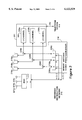
- FIG. 4 is a detailed block diagram of the portion of a Remote Antenna Signal Processor (RASP) which is connected to a Base Transceiver Station (BTS) and transmits telephony signals originating at the telephone system, via a broadband distribution network to a Remote Antenna Driver (RAD) which is located in an area in which tower mounted antenna signal coverage is poor, non-existent, or interfered with, in accordance with the teaching of the present invention;
- RASP Remote Antenna Signal Processor
- BTS Base Transceiver Station
- RAD Remote Antenna Driver
- FIG. 5 is a detailed block diagram of the portion of a Remote Antenna Signal Processor (RASP) which is connected to a Base Transceiver Station (BTS) and receives telephony signals originating at wireless telephones and carried via the broadband distribution network from a Remote Antenna Driver (RAD) which is located in an area in which tower mounted antenna signal coverage is poor, non-existent, or interfered with, in accordance with the teaching of the present invention;
- RASP Remote Antenna Signal Processor
- BTS Base Transceiver Station
- RAD Remote Antenna Driver
- FIG. 6 is a detailed block diagram of the portion of a Remote Antenna Driver (RAD) that transmits telephony signals received via a Broadband Distribution Network from a Base Transceiver Station (BTS) and a RASP to wireless telephones in accordance with the teaching of the present invention; and
- RAD Remote Antenna Driver
- FIG. 7 is a detailed block diagram of the portion of a Remote Antenna Driver (RAD) that receives telephony signals from wireless telephones, and forwards the signals via the broadband distribution network to the RASP and BTS in accordance with the teaching of the present invention.
- RAD Remote Antenna Driver
- circuit elements are assigned three digit reference numbers.
- the first digit of each reference number indicates in which Figure of the drawing an element is shown.
- the second and third digits of each reference number indicate specific circuit elements. If the same circuit element appears in more than one Figure of the drawing, the second and third digits of the reference number for that circuit element remain the same and only the first digit of the reference number changes to indicate the Figure of the drawing in which the circuit element is located.
- RAD 217 in FIG. 2 is the same RAD labeled 117 in FIG. 1.
- reverse direction refers to any signals traveling from a RAD 117 toward Telephone System 114
- forward direction refers to any signals traveling from Telephone System 114 toward a RAD 117.
- downstream In the cable television industry the "forward direction” is referred to as "downstream”
- upstream This is mentioned because the present invention may be implemented into a wireless telephone system as described herein utilizing a cable television distribution cable. Other distribution networks such as fiber optic, wireless, and other types of networks that may exist in the future; and such networks may be dedicated or shared.
- telephony signals includes voice, data, facsimile and any other type of signals that are sent over a telephone network now or the future.
- FIGS. 3 through 7 reference is often made to an element such as RAD 117, RASP 118 and BTS 111 in FIG. 1 to remind the reader what circuits these Figures are part of, although the reference numbers 111, 117 and 118 do not actually appear in the Figure being described.
- Wireless telephony systems commonly utilize a plurality of remote transceivers (Base Transceiver Stations) with associated antenna towers on hilltops to handle wireless telephone traffic in a number of contiguous areas called cells.
- BTSs Base Transceiver Stations
- multiple transceivers (BTSs) being located to provide area coverage, and even overlapping areas of signal coverage, there may still be "blind" areas of signal coverage caused by hills, tunnels, tall structures, etc.
- RAD Remote Antenna Driver
- the RAD is connected via a broadband distribution network, such as cable television cable or dedicated fiber strand/byndle, to a Remote Antenna Signal Processor (RASP) which is co-located with the existing Base Transceiver Station (BTS) with tower mounted antenna.
- RASP Remote Antenna Signal Processor
- An encoded telephony signal being transmitted by a BTS using its hilltop antenna is also carried via a dedicated cable or a broadband distribution cable or dedicated fiber strand/bundle in the blind area to the associated RADs to be simultaneously broadcast ("simulcast") in the blind area.
- Signals being received by the RAD from a wireless telephone are carried by the dedicated cable or broadband distribution cable or fiber and combined with the signal being received by the hilltop antenna.
- using RADs within the coverage area of a hilltop antenna may be shaped, and also used to cover blind spots. This is different than a repeater to and from which signals that are to be repeated are transmitted to and from the BTS over the airwaves, not by a dedicated cable/fiber, and be received in areas where the transmitted signal may cause other spectrally related reception problems.
- FIG. 1 is shown a diagram of a conventional wireless telephony system which utilizes a number of antenna towers 110a-e, typically located on hilltops or other high locations such as tall buildings, to provide wireless telephone signal coverage in assigned cells 112a-e.
- the signal coverage of each cell 112a-e provides complementary and sometimes overlapping coverage with adjacent cells.
- Each antenna tower 110a-e has a Base Transceiver Station (BTS) 111a-e associated therewith as is known in the art.
- BTS 111a-e encodes analog or digital telephony signals received from a telephone system 114 for transmission to wireless telephones.
- the type of decoding that is done depends upon the type of system and includes, but is not limited to, the well-known CDMA and GSM systems.
- BTSs 111a-e are connected via a telephone distribution network 113 to a telephone system 114 in a manner well known in the art.
- Telephone distribution network 113 is often a T1 carrier.
- Telephone distribution network 113 is comprised of wire, coaxial cable, fiber-optic cable, and radio links as is also known in the art. Wire, coaxial cable, and fiber-optic cable are often hung on telephone poles (not shown), but are also buried. Often hung on the same telephone poles is a cable television distribution network 115 which usually comprise coaxial and fiber-optic cable as previously mentioned. For this reason, in FIG. 1 only single, dark lines are shown, designated both 113 and 115 to represent both telephone distribution network 113 and cable television distribution network 115. In FIG. 1 there are three branches, all designated 113 and 115.
- the cable television distribution network is referred to as a broadband distribution network since any broadband network may be utilized.
- an area designated 116 that represents a physical area in which wireless telephone service is not adequately provided due to hills, tunnels and/or tall structures. Utilizing the teaching of the present invention, improved wireless telephone service is provided in blind areas such as area 116.
- wireless communications signals carried between a wireless telephone (not shown) in an area 116 and a BTS 111 are carried over an alternate path, which includes a Remote Antenna Signal Processor (RASP) 118, broadband distribution network 115, and Remote Antenna Drivers (RADs) 117a&b.
- RASP Remote Antenna Signal Processor
- RADs Remote Antenna Drivers
- an encoded telephony signal which originated at Telephone System 114, and destined for a wireless telephone (not shown) located in blind area 116, is being transmitted by BTS 111c and antenna 110c; the same encoded telephony signal is also sent via RASP 118c in a frequency division multiplexing format over broadband distribution network 115 to RAD 117a which simultaneously transmits ("simulcasts") at low power the same telephony signal in area 116.
- other broadband distribution networks other than cable television distribution network 115, may be utilized to connect each RASP 118 and RAD 117.
- a dedicated cable may be provided to interconnect each RASP 118 and RAD 117.
- Telephony signals originating from a wireless telephone (not shown) located in area 116 are received by RAD 117a which adds control signals and sends them in frequency division multiplexed signaling via broadband distribution network 115 and RASP 118c to BTS 111c. If the wireless telephone is in the portion of area 116 closer to cell 112e, its telephony signals are carried by RAD 117b and RASP 118e. More detailed descriptions of the operation of RADs 117 and RASPs 118 are given further in this Detailed Description.
- each of BTSs 111a-e are a plurality of transceiver modules (not shown), as is known in the wireless telephony art, each of which operates at a single channel frequency at a time, and which can handle a predetermined maximum number of telephone calls from wireless telephones.
- these transceiver modules in the base transceiver stations 111 are also referred to as channel card modules and radio modules.
- Each RAD 117a&b has three antennas, as shown, used to transmit signals to and receive signals from remote wireless telephones (not shown) operating in blind area 116.
- One antenna is used to transmit encoded, wireless telephony signals to wireless telephones, while the other two antennas are used to receive wireless encoded, telephony signals from wireless telephones.
- One receive antenna is called the primary antenna, and the other receive antenna is called the diversity antenna.
- the two receive antennas are physically spaced and cooperate to minimize signal fading and thereby provide continuous signal reception from wireless telephones.
- FIG. 2 is shown a block diagram of a prior art BTS 211 with tower mounted antennas 210, and the implementation of the present invention showing how a RASP 218, Broadband Distribution Network 215, and RAD 217 are integrated with a BTS 211.
- BTS 211 is connected via a telephone distribution network 213 to a telephone system 114.
- Each prior art BTS 211 has three channel circuits designated alpha 219a, beta 219b, and gamma 219c. Each of these three channel circuits 219a-c receives analog or digital telephony signals from telephone system 114, and encodes them. The type of encoding that is done depends upon the type of wireless telephone system and includes, but is not limited to, the well-known CDMA and GSM systems.
- the encoded signals are transmitted via a transmit antenna 210 to be received by a wireless telephone (not shown) operating in the cell in which BTS 111 is located. In FIG. 2 three sets of antennas 210 are shown. Antenna 210a is used by channel circuit 219a, antenna 210b is used by channel circuit 219b, and antenna 210c is used by channel circuit 219c.
- each of the three prior art channel circuits 219a-c receives encoded telephony signals via its associated antenna 210a-c from wireless telephones (not shown) operating in the cell in which BTS 211 is located.
- the particular one of channel circuits 219a-c that receives the signals decodes the telephony signal to analog or digital format and sends it via telephone distribution network 213 to telephone system 114.
- a directional coupler 220a-c is connected between each of the channel circuits 219a-c and its associated one of antennas 210a-c. These couplers 220a-c are used to tap off telephony signals being transmitted via antennas 210a-c and, using RASP 218 and Broadband Distribution Network 215, sends the encoded telephony signals to RAD 217 for simultaneous (“simulcast") transmission in blind area 116.
- These directional couplers 220a-c are also used to take telephony signals received by RAD 217 from wireless telephones (not shown) operating in blind area 116 and combine them with signals being received by antennas 210a-c for input to BTS 211 channel circuits 219a-c.
- the coupler can include electronic interfaces as well.
- each RASP 218 has three channel circuits designated alpha channel 218a, beta channel 218b, and gamma channel 218c that correspond to the alpha, beta and gamma channels 219a-c in BTS 211, as shown in FIG. 2.
- the circuitry in channel circuits 218a-c of RASP 218 translates the frequency of encoded telephony signals passing between RAD 217 and BTS 211, as necessary for transmission over the Broadband Distribution Network 215.
- circuitry in channel circuits 218a-c of RASP 218 adds control signals to encoded telephony signals going to RAD 217, and separates control signals generated by RAD 217 from encoded telephony signals received from RAD 217. This operation is described in greater detail further in this Detailed Description.
- RAD 217 has three antennas 221a-221c.
- Antenna 221a is used to transmit telephony signals that originated at telephone system 114 and being sent to a wireless telephone (not shown) in blind area 116.
- Antennas 221b and 221c are both receive antennas, with antenna 221b being called the primary receive antenna, and antenna 221c being called the secondary receive antenna.
- Antennas 221b&c both receive telephony signals originating from a wireless telephone (not shown) in blind area 116 and forwards both signals in frequency multiplexed format to RASP 218.
- Antennas 221b&c are physically spaced and cooperate to minimize signal fading and thereby provide continuous signal reception from wireless telephones operating in blind area 116. The operation of RAD 217 is described in greater detail further in this Detailed Description
- FIG. 3 therein is shown a general block diagram of a typical prior art Base Transceiver Station (BTS) 311 used in a prior art wireless telephony system.
- BTS Base Transceiver Station
- FIG. 3 there are three channel circuits in each BTS. As all three channel circuits are identical, only the alpha channel circuitry 319a is shown in FIG. 3 for the sake of simplicity.
- FIG. 3 are two rows of circuits.
- the upper row of FIG. 3 shows the reverse direction circuitry of alpha channel 319a that carries telephony signals from a wireless telephone (not shown) to telephone system 114.
- the lower row of FIG. 3 shows the forward direction circuitry of alpha channel 319a that carries telephony signals originating at telephone system 114 and carries them toward a wireless telephone (not shown).
- an RF carrier signal modulated with an encoded wireless telephony signal that is received by antenna 210a, or is received via a RAD 117 in blind area 116 via the alpha channel 218a of the associated RASP 218, is input via bidirectional coupler 220a to filter 347 which removes spurious signals at the input of BTS 311.
- the received RF carrier signal is then amplified by amplifier 348 and input to transceiver 349.
- Transceiver 349 is used to translate the frequency of the RF carrier signal, received from either RASP circuit 218a or antenna 210a, via bidirectional coupler 220a, to an IF carrier signal which is input to demodulator 350.
- Demodulator 350 extracts the encoded telephony signal from the IF carrier signal in a manner well-known in the art.
- the decoded signal may either be an analog or digital signal, depending on the type of system.
- the well known GSM system is used wherein the carrier signal is phase shift key modulated.
- the encoded, analog telephony signal is extracted.
- the encoded, analog telephony signal is then input to analog to digital converter 351 which digitizes the encoded analog telephony signal.
- the now digitized and encoded telephony signal is then input to decoder 352 which decodes the signal to obtain the digitized telephony signal which is then sent to Telephone System 114.
- decoder 352 decodes the signal to obtain the digitized telephony signal which is then sent to Telephone System 114.
- the type of decoding that is done depends upon the system, and the types include, but are not limited to, the well-known CDMA and GSM systems.
- digitized telephony signals received from Telephone System 115 are input to encoder 353.
- the type of encoding that is done depends upon the type of system and includes, but is not limited to, the well-known CDMA and GSM systems.
- the encoded digital telephony signal is then input to digital to analog converter 354 which converts the telephony signal into an analog signal.
- the analog, encoded telephony signal is then input to modulator 355 which, in the prior art Base Transceiver Station (BTS) 116 shown in FIG. 6, phase shift key modulates an IF carrier signal in a matter well-known in the art.
- BTS Base Transceiver Station
- the IF carrier signal modulated by the analog, encoded telephony signal, is then input to transceiver 366 which translates the IF carrier signal frequency to an RF carrier signal.
- the modulated RF carrier signal is then amplified by amplifier 367, spurious signals are filtered out by filter 368 and the RF carrier signal is sent to RASP 218.
- RASP 218 receives the RF carrier signal and processes it in the manner described in greater detail further in this Detailed Specification.
- FIG. 4 is shown a detailed block diagram of the portion of the Remote Antenna Signal Processor (RASP) 218 in FIG. 2 that processes telephony signals received from the Base Transceiver Station (BTS) 211 and forwards them via Broadband Distribution Network 215 and RAD 117 to a wireless telephone (not shown) in blind area 116.
- RASP Remote Antenna Signal Processor
- RASP circuit Within the RASP circuit are three parallel circuits 418a-c. These three circuits are referred to as alpha, beta and gamma channels in the RASP and they operate in the same manner except for their frequency of operation. To simplify the description of the RASP circuit, only one of these three circuits, alpha channel 418a, is shown and described in detail. Common circuitry is also described.
- Telephony signals received from BTS 111 on the alpha channel 218a are input to bandpass filter 432 to remove all out of band signals.
- the filtered telephony signals are then input to mixer 433 along with a signal from oscillator OSC5.
- the heterodyning process of mixer 433 produces a number of unwanted signals which are removed by bandpass filter 435 which passes only the desired telephony signals at an IF frequency.
- the filtered telephony signals in alpha channel 418a are then input to a second mixer 436 along with input from oscillator OSC6.
- Oscillator OSC6, and other oscillators in the alpha, beta and gamma channels are each controlled by a microprocessor (not shown) and are set to different frequencies depending on the frequencies that the frequency multiplexed telephony signals in the alpha, beta and gamma channel are to be transmitted over Broadband Distribution Network 115.
- All signals output from mixer 436 are input to combiner 438 which also has similar inputs from the mixers (not shown) in the beta and gamma channels.
- Combiner 438 combines the signals from the alpha, beta and gamma channels 218a-c into a first frequency multiplexed signal which is input to bandpass filter 439 where all unwanted frequencies from the heterodyning process are removed. Only the desired telephony signals on the alpha, beta and gamma channels are passed through filter 439 to mixer 440.
- Mixer 440 is used to shift the frequency of the telephony signals to their assigned frequency on broadband distribution network 115. To accomplish this mixing process there is another input to mixer 440 from oscillator OSC7. The frequency of oscillator OSC7 is set by the microprocessor (not shown).
- bandpass filter 443 only passes the desired frequency multiplexed telephony signals in the alpha, beta and gamma channels.
- the frequency multiplexed telephony signals from all three channels are amplified by amplifier 444 before being input to diplexer 445. There is a second input to diplexer 445 that is now described.
- BTS 111 On lead f from BTS 111 is a reference signal received from BTS 111.
- This reference signal is used by all oscillators in RASP 118, and is also transmitted to and used as a reference oscillator signal for all local oscillators in RADs 117.
- FIG. 5 is shown a block diagram of the reverse direction portion of a Remote Antenna Signal Processor (RASP) 118.
- the reverse direction circuitry processes telephony and control signals received from wireless telephones (not shown) and RADs 117, and received via Broadband Distribution Network 115, and forwards them to BTS 111.
- RASP Remote Antenna Signal Processor
- RASP circuits 511a, 511b and 511c Within the RASP circuit are three parallel channel circuits 511a, 511b and 511c. These three circuits are referred to as alpha, beta and gamma channels and they operate in the same manner except for their frequency of operation to handle telephony signals in different channels. To simplify the description of the reverse direction RASP circuit shown in FIG. 5, only alpha channel circuit 511a is described in detail. There may be more than three such channel circuits in a RASP.
- Telephony signals from a wireless telephone (not shown), and control signals from a RAD 117 that is carrying the telephony signals, are carried over Broadband Distribution Network 115 to bandpass filter 523 at the input of alpha channel 511a. These telephony and control signals are divided for further processing as described further in this detailed description.
- Filter 523 removes out of band signals that are present on Broadband Distribution Network 115 before the telephony and control signals are input to signal divider 524.
- Divider 524 divides and applies the combined telephony and control signals to both divider 526 and signal detector 525.
- Signal detector 525 separates the control signals from the telephony signal and forwards the control signals to a microprocessor (not shown) for processing.
- the microprocessor analyzes the control signals and causes circuit adjustments to be made in RASP 118 and RAD 117.
- Divider 524 also applies the telephony signal to divider 526 which again divides the signal, which telephony signal includes the combined signals from the primary receive antenna and diversity receive antenna of a RAD 117, and applies them to mixers 527a and 527b.
- the telephony signal received by the primary receive antenna and diversity receive antenna from a single RAD 117 are frequency multiplexed together.
- Mixers 527a and 527b are used to separate these two frequency multiplexed telephony signals.
- Mixer 527a has a second input from oscillator OSC1, and mixer 527b has a second input from oscillator OSC2.
- the frequency of oscillators OSC1 and OSC2 are different and the mixing process of mixers 527a and 527b causes the modulated carrier signal output from each of the mixers to have the same intermediate frequency (IF) carrier signal.
- the frequency of oscillators OSC1 and OSC2 are controlled by the microprocessor (not shown) and are set according to the assigned frequency of operation for the alpha channel on Broadband Distribution Network 115.
- mixers 527a and 527b produce a number of unwanted signals which are removed respectively by bandpass filters 529a and 529b, and which respectively pass only the desired telephony signal from the primary receive antenna and the diversity receive antenna.
- mixer 530a Only the primary receive antenna telephony signal is output from filter 529a and is input to mixer 530a where it is mixed with a signal from oscillator OSC3.
- the heterodyning process of mixer 530a is used to translate the intermediate frequency (IF) carrier signal, modulated with the primary receive antenna telephony signal, to a radio frequency (RF) carrier signal that is transmitted via path alpha 1 to BTS 111.
- IF intermediate frequency
- RF radio frequency
- the heterodyning process of mixer 530b is used to translate the IF carrier signal, modulated with the secondary receive antenna telephony signal, to an RF carrier signal that is transmitted via path alpha 2 to BTS 111.
- the heterodyning process of mixer 530b also produces a number of unwanted signals that are removed by bandpass filter 531b.
- FIG. 6 is shown a detailed block diagram of the downstream or forward circuitry of RAD 117 that carries telephony signals to wireless telephones (not shown).
- RAD 117 hangs from and is connected to Broadband Distribution Network 115.
- Transformer 642 is an impedance matching transformer having 75 ohm primary and 50 ohm secondary windings.
- Broadband Distribution Network 115 is coaxial cable
- the primary winding of transformer 642 is wired in series with the center conductor of the coaxial cable.
- Transformer 642 is used to connect frequency multiplexed telephony and control signals carried on Broadband Distribution Network 115 from RASP 118 to the input of this RAD circuit. Only a RAD 117, the receive frequency of which has been tuned to the particular frequency of telephony and control signals on Broadband Distribution Network 115 can actually receive and forward the telephony signals to a wireless telephone (not shown).
- All RADs 117 connected to Broadband Distribution Network 115 receive control signals directed toward any one of the RADs. However, each RAD 117 has a unique address that prefixes each control signal and is used by each RAD 117 to accept only control signals directed specifically to it by RASP 118.
- the frequency multiplexed telephony and control signals received by the RAD circuitry in FIG. 6 from Broadband Distribution Network 115 are input to band pass filter and amplifier 643.
- Filter 643 passes all possible frequency multiplexed telephony and control signals that are carried on Broadband Distribution Network 115, and excludes other unwanted signals carried on Network 115.
- Circuit 643 also amplifies the signals that pass through filter 642.
- the signals output from filter 643 are input to mixer 644 along with a signal from local oscillator 645.
- the frequency of local oscillator 645 is digitally controlled at its input 645a by a microprocessor (not shown) responsive to frequency reference signals received from RASP 118, as briefly described hereinabove.
- mixer 644 results in multiple frequencies being output from the mixer as is known in the art and unwanted frequencies are blocked by band pass filter and amplifier 646 which passes only desired signals.
- the selected set of telephony and control signals are amplified and are input to mixer 647.
- local oscillator 649 is digitally controlled at its control input 649a by the microprocessor (not shown) responsive to reference signals received from RASP 118.
- mixer 647 combines the signals input to it and provides a number of output signals at different frequencies. All these frequencies are input to an attenuator 650 which is used to adjust the gain level of the signals. Attenuator 650 is part of the gain control system and is digitally controlled at its input 650a in 1/2 dB steps by the microprocessor (not shown), responsive to gain control signals received from RASP 118.
- the gain adjusted signal output from attenuator 650 is input to SAW filter and amplifier 651. Due to the sharp filtering operation of SAW filter 651, even spurious signals close to the desired telephony and control signals are removed. Control signals frequency multiplexed with the telephony signal do not pass through SAW filter 651. Instead, the control signals are input to mixer 648 as is described further in this specification.
- the telephony signals passing through SAW filter 651 are input to digitally controlled attenuator 652 to adjust the gain level of the signal before it is input to mixer 653 along with the output of microprocessor controlled local oscillator 654.
- Attenuator 652 is part of the gain control system and is digitally controlled at its control input 652a in 2 dB steps by the microprocessor (not shown), responsive to gain control signals received from RASP 118.
- the amplitude adjusted telephony signal output from attenuator 652 is input to mixer 653 along with a signal from digitally controlled oscillator 654.
- Oscillator 654 is also controlled by the microprocessor, responsive to gain control signals received from RASP 118, in the same manner as local oscillators 645, 649 and 660.
- Mixer 653 combines the two signals in a manner well-known in the art to produce several output signals, one of which is the telephony signal now having the desired RF carrier frequency for transmission of the telephony signal to a remote wireless telephone (not shown).
- the signals output from mixer 653 are input to band pass filter and amplifier 655.
- Band pass filter 655 passes only the desired RF carrier frequency.
- the signal is also amplified before being input to signal divider 656.
- a portion of the telephony signal input to divider 656 is divided and input to bit and power monitor 657, while the remainder of the signal is input to band pass filter and amplifier 658.
- Bandpass filter 658 assures that there are no extraneous signals combined with the desired telephony signal, amplifies same, and applies it to power amplifier 659.
- Power amplifier 659 amplifies the telephony signal and couples it to transmit antenna 621a. The signal is transmitted within the physical area for signal coverage of RAD 117 and is received by a remote wireless telephone (not shown) which is in this area.
- the telephony signal input to bandpass filter 658 is divided by divider 656 and the sample is input to BIT and Power Monitor 657.
- the level of the telephony signal is reported to the microprocessor (not shown) which reports same to RASP 118 as part of the control signals.
- the output of power amplifier 659 is also sampled and input to BIT and Power Monitor 657 which reports the signal level to the microprocessor which in turn reports it to RASP 118.
- This signal level measurement is used in concert with attenuators 650 and 652, as controlled by RASP 118, to adjust the power level of the telephony signal to be applied to the transmit antenna. If the signal level output from power amplifier 659 is too high, and cannot be adjusted within specification by attenuators 650 and 652, microprocessor will shut down this RAD 117.
- the output of mixer 648 is input to reference channel oscillator 662 and forward control channel circuit 661.
- Circuit 661 accepts only control signals sent from RASP 118 and sends them to the microprocessor.
- Control signals have a prefixed RAD address as part of the control signals and each RAD 117 has a unique address. Therefore, the microprocessor in each RAD 117 can recognize and accept only control signals directed to it from RASP 118.
- a RAD 117 When a RAD 117 receives control signals directed to it by RASP 118, the microprocessor responds thereto to perform the action required by RASP 118.
- the control signal may ask for the settings of the local oscillators and attenuators, and this information is returned to RASP 118 using a control signal oscillator as described herein.
- the control signal from RASP 118 may also indicate revised settings for local oscillators and attenuators.
- the microprocessor makes the required changes to the circuits and then sends a confirmation signal back to RASP 118 indicating that the requested changes have been made.
- the control signal from RASP 118 may also request information concerning the outputs from bit and power monitor 657. Responsive to any of these control signals the microprocessor performs the requests.
- Reference channel oscillator 662 processes the output of mixer 648 to obtain the reference oscillator signal sent from RASP 118, and generates a phase lock loop reference signal that is used to provide a master frequency to all local oscillators within RAD 117 to match their frequency of operation with RASP 118.
- FIG. 7 is shown a detailed block diagram of the upstream or reverse circuitry within Remote Antenna Driver (RAD) 117 that carries telephony signals from a wireless telephone (not shown), and via Broadband Distribution Network 115, to RASP 118.
- RAD Remote Antenna Driver
- primary receive antenna 721b is connected to a first portion of the circuitry in FIG. 7, and that circuitry is identical to a second portion of the circuitry that is connected to diversity receive antenna 721c.
- the telephony signals received by both antennas 721b and 721c from a wireless telephone are initially processed in parallel, then the two received signals are both frequency multiplexed together and both are returned via Broadband Distribution Network 115 to remote RASP 118 to be processed.
- Telephony signals from a wireless telephone (not shown in FIG. 7) operating in the blind area 116 assigned to RAD 117b are received by primary receive antenna 721b.
- the signals are input to an isolator 723a which isolates antenna 721b from the downstream RAD circuit shown in FIG. 6.
- the received telephony signal is then input to directional coupler 724a that has a second signal input thereto from power divider 743 and gain tone oscillator 742 which are used for gain control measurement purposes.
- the telephony signal (modulated RF carrier) received from a remote wireless telephone, and the gain tone, are applied via directional coupler 724a to a combined band pass filter and amplifier 725a.
- the signals are amplified and extraneous signals are filtered from the received telephony signal by bandpass filter 725a.
- the operation just described also applies to isolator 723b, coupler 724b and bandpass filter and amplifier 725b.
- the amplified and filtered telephony signal is then input to mixer 726a which is used along with SAW filter 729a to assist in filtering of the spread spectrum, digital telephony signal.
- Mixer 726a also has input thereto a signal from local oscillator 727. This signal from local oscillator 727 is input to divider 728 which applies the signal to both mixers 726a and 726b while providing isolation between these two mixers.
- the frequency of local oscillator 727 is digitally controlled and is determined by a binary control word applied to its control input 727a from a microprocessor (not shown), responsive to control signals received from RASP 118. Similarly, control signals from remote RASP 118 causes the microprocessor to set the frequency of digitally controlled local oscillators 733a and 733b.
- mixer 726a results in multiple frequencies being output from the mixer as is known in the art, but due to the frequency of oscillator 727, most of the signals present at the input of RAD circuit 723a from antenna 721b are shifted far outside the band of frequencies which can pass through SAW filter 729a. Only the desired signals can pass through SAW filter 729a. This frequency shift also helps to prevent leak through of unwanted signals present at the input of circuit 723a because they are blocked by narrow bandpass filter 725a which is passing signals of a frequency far from the signals applied to SAW filter 729a. Due to the sharp filtering action of SAW filter 729a, even spurious signals close to the desired telephony and control tone signals are removed. The same filtering operation applies to mixer 726b and SAW filter 729b.
- step attenuator 730a which is used to adjust the gain level of the signal in one-half dB steps.
- the amount of attenuation provided by step attenuator 730a is controlled by a binary word at its control input 731a from the microprocessor (not shown).
- the control of step attenuators 730a, 730b, and 736 is accomplished responsive to control signals from RASP 118 as part of a gain control operation that assures that the signal level of telephony signals appearing at the input of RASP 118 from RAD 117 is within an acceptable range.
- Attenuator 730b in the parallel channel handling the telephony signals from diversity receive antenna 721c performs the same function.
- the telephony signal that is output from step attenuator 730a is input to mixer 732a along with a fixed frequency signal from local oscillator 733a.
- Mixer 732a is used to shift the frequency of the telephony and gain tone signals to the frequency required to apply the signals to Broadband Distribution Network 115. This same operation applies to the telephony and gain tone signals output from mixer 732b.
- the frequency of oscillators 733a and 733b is determined by binary words applied to their control input 733c.
- a control signal is sent from RASP 118 which causes the microprocessor to set the frequency of local oscillators 733a and 733b.
- the frequency of the telephony signal output from step attenuator 730a is the same as the frequency of the telephony signal output from step attenuator 730b.
- the frequency of local oscillator 733a is different from the frequency of local oscillator 733b.
- the result is that the RF carrier frequency of the telephony and gain tone signals output from mixer 732a is different than the RF carrier frequency of the telephony and gain tone signals output from mixer 732b.
- both primary receive antenna 721b and diversity receive antenna 721c signals are both sent to RASP 118 and BTS 111 in frequency multiplexed form for processing.
- all carrier frequencies are within the frequency band of the assigned wireless telephony channel on Broadband Distribution Network 115.
- the telephony signals received by primary receive antenna 721b and diversity receive antenna 721c are frequency multiplexed together and sent via Broadband Distribution Network 115 to RASP 118.
- combiner 734 is utilized.
- Combiner 734 has the telephony and gain tone signals output from both mixers 732a and 732b input thereto. As described in the previous paragraph these two received telephony signals modulate carriers that are at different frequencies, but both frequencies are in an assigned channel of Broadband Distribution Network 115.
- Combiner 734 combines the two sets of signals so they are frequency multiplexed together.
- the combined signal is input to bandpass filter and amplifier 735 which removes spurious frequencies created by the mixing action in circuits 732a and 732b, and amplifies the signals that pass through the filter.
- the combined and filtered telephony and gain tone signals are input to step attenuator 736 to adjust the gain level of the signals. Similar to the operation of the previously described step attenuators, this digitally controlled attenuator is set responsive to gain control signals received from remote RASP 118 as part of the gain control operation.
- the frequency multiplexed telephony and gain tone signals output from step attenuator 736 are input to mixer 737 which has a second input from control signal oscillator 738.
- the frequency of control signal oscillator 738 is set responsive to a binary signal on its control leads 738a from the microprocessor.
- RASP 118 is the origin of the control signal used to set the frequency of control signal oscillator 738.
- control input 738a Responsive to different control signals received from RASP 118, the microprocessor (not shown) applies signals to control input 738a. These microprocessor signals cause control signal oscillator 738 to produce an information signal.
- the information signal indicates various information about RAD 117, but particularly including the settings of step attenuators 730a, 730b and 736, to RASP 118 as part of the gain control operation. RASP 118 uses this information to keep an updated status regarding RAD 117.
- the output from mixer 737 now has five signals frequency multiplexed together to be returned via Broadband Distribution Network 115 to RASP 118.
- the signals are the telephony signal received by primary receive antenna 721b, the telephony signal received by diversity receive antenna 721c, the gain tone signal output from gain tone oscillator 742 as applied to both primary receive and diversity receive paths, and the system information signal output from control signal oscillator 738.
- This frequency multiplexed signal output from combiner 737 is input to band pass filter and amplifier 739 to remove any extraneous signals and amplify the desired signals before they are input to Broadband Distribution Network 115 and sent to RASP 118.
- Transformer and coupler 740 is used to couple the frequency multiplexed signals described in the previous paragraphs to Broadband Distribution Network 115.
- the transformer 740 is an impedance matching transformer having 50 ohm primary and 75 ohm secondary windings.
- Broadband Distribution Network 115 uses coaxial cable
- the secondary winding of transformer 740 is wired in series with the center conductor of the coaxial
- the invention in accordance with claim I wherein cable.
- RAD 117 hangs from the coaxial cabling of the Broadband Distribution Network 115 to which it is connected. In other applications, such as with fiber optic cable, other well known frequency conversion and signal coupling techniques are used.
- a small portion of the frequency multiplexed signals passing through transformer and coupler 740 is coupled to Built In Test (BIT) and power monitor 741.
- Monitor 741 samples the signal level of the combined signals that are being input to Broadband Distribution Network 115 and reports this information to RASP 118 via control signal oscillator 738 which has been previously described. If the output signal level is too high and the level cannot be corrected, the microprocessor will shut down RAD 117 and report this to RASP 118.
- BIT Built In Test
Abstract
Description
Claims (14)
Priority Applications (5)
| Application Number | Priority Date | Filing Date | Title |
|---|---|---|---|
| US09/042,950 US6122529A (en) | 1998-03-17 | 1998-03-17 | Simulcast with hierarchical cell structure overlay |
| AU30090/99A AU3009099A (en) | 1998-03-17 | 1999-03-17 | Simulcast with hierarchical cell structure overlay |
| PCT/US1999/005844 WO1999048309A1 (en) | 1998-03-17 | 1999-03-17 | Simulcast with hierarchical cell structure overlay |
| CA002324231A CA2324231C (en) | 1998-03-17 | 1999-03-17 | Simulcast with hierarchical cell structure overlay |
| EP99911451A EP1064796A4 (en) | 1998-03-17 | 1999-03-17 | Simulcast with hierarchical cell structure overlay |
Applications Claiming Priority (1)
| Application Number | Priority Date | Filing Date | Title |
|---|---|---|---|
| US09/042,950 US6122529A (en) | 1998-03-17 | 1998-03-17 | Simulcast with hierarchical cell structure overlay |
Publications (1)
| Publication Number | Publication Date |
|---|---|
| US6122529A true US6122529A (en) | 2000-09-19 |
Family
ID=21924625
Family Applications (1)
| Application Number | Title | Priority Date | Filing Date |
|---|---|---|---|
| US09/042,950 Expired - Lifetime US6122529A (en) | 1998-03-17 | 1998-03-17 | Simulcast with hierarchical cell structure overlay |
Country Status (5)
| Country | Link |
|---|---|
| US (1) | US6122529A (en) |
| EP (1) | EP1064796A4 (en) |
| AU (1) | AU3009099A (en) |
| CA (1) | CA2324231C (en) |
| WO (1) | WO1999048309A1 (en) |
Cited By (83)
| Publication number | Priority date | Publication date | Assignee | Title |
|---|---|---|---|---|
| US20010044292A1 (en) * | 1999-12-22 | 2001-11-22 | Hyundai Electronics Industries Co., Ltd. | RF block of mobile communication base station |
| US6336042B1 (en) * | 1998-06-05 | 2002-01-01 | Transcept, Inc. | Reverse link antenna diversity in a wireless telephony system |
| US6349200B1 (en) * | 1997-12-24 | 2002-02-19 | Transcept, Inc. | Monitoring and command system for transceivers used to inter-connect wireless telephones to a broadband network |
| US6374119B1 (en) * | 1999-05-27 | 2002-04-16 | Hansol Pcs Co. Ltd. | System and method for in-building mobile communications |
| US6374124B1 (en) * | 1997-12-24 | 2002-04-16 | Transcept, Inc. | Dynamic reallocation of transceivers used to interconnect wireless telephones to a broadband network |
| WO2002075945A1 (en) * | 2001-03-19 | 2002-09-26 | Superconductor Technologies, Inc. | Apparatus and methods for improved tower mountable systems for cellular communications |
| US6513163B1 (en) * | 1999-05-20 | 2003-01-28 | Transcept, Inc. | Embedded forward reference and control |
| US6594473B1 (en) * | 1999-05-28 | 2003-07-15 | Texas Instruments Incorporated | Wireless system with transmitter having multiple transmit antennas and combining open loop and closed loop transmit diversities |
| US20040057393A1 (en) * | 1999-04-21 | 2004-03-25 | Opencell Corporation | Architecture for signal distribution in wireless data networks |
| US20040089828A1 (en) * | 2002-10-18 | 2004-05-13 | Werth Albert A. | Conduit clamp |
| US20040106387A1 (en) * | 2002-12-03 | 2004-06-03 | Adc Telecommunications, Inc. | Small signal threshold and proportional gain distributed digital communications |
| US20040106435A1 (en) * | 2002-12-03 | 2004-06-03 | Adc Telecommunications, Inc. | Distributed digital antenna system |
| US20040198451A1 (en) * | 2002-06-11 | 2004-10-07 | Andrew Corporation | Tower top antenna structure with fiber optic communications link |
| US20040203339A1 (en) * | 2002-12-03 | 2004-10-14 | Bauman Donald R. | Distributed signal summation and gain control |
| US20050018655A1 (en) * | 1999-04-21 | 2005-01-27 | Opencell, Inc. | Architecture for signal and power distribution in wireless data network |
| US20050018630A1 (en) * | 1999-04-21 | 2005-01-27 | Opencell Corp. | Architecture for signal distribution in wireless data network |
| US20050026588A1 (en) * | 2001-03-19 | 2005-02-03 | Superconductor Technologies, Inc. | Communication systems incorporating HTS filters and non-linear modulators such as RF-light modulators |
| US20060062194A1 (en) * | 1998-06-01 | 2006-03-23 | Fiut Brian D | Integration of remote microcell with CDMA infrastructure |
| US7599711B2 (en) | 2006-04-12 | 2009-10-06 | Adc Telecommunications, Inc. | Systems and methods for analog transport of RF voice/data communications |
| US20100202356A1 (en) * | 2009-02-12 | 2010-08-12 | Adc Telecommunications, Inc. | Backfire distributed antenna system (das) with delayed transport |
| US7962111B2 (en) | 2002-02-25 | 2011-06-14 | ADC Wireless, Inc. | Distributed automatic gain control system |
| US20130070772A1 (en) * | 2011-09-16 | 2013-03-21 | Rogers Communications Inc. | Coaxial cable distribution of catv and wireless signals |
| US8532492B2 (en) | 2009-02-03 | 2013-09-10 | Corning Cable Systems Llc | Optical fiber-based distributed antenna systems, components, and related methods for calibration thereof |
| US8639121B2 (en) | 2009-11-13 | 2014-01-28 | Corning Cable Systems Llc | Radio-over-fiber (RoF) system for protocol-independent wired and/or wireless communication |
| US8644844B2 (en) | 2007-12-20 | 2014-02-04 | Corning Mobileaccess Ltd. | Extending outdoor location based services and applications into enclosed areas |
| US8718478B2 (en) | 2007-10-12 | 2014-05-06 | Corning Cable Systems Llc | Hybrid wireless/wired RoF transponder and hybrid RoF communication system using same |
| US8831428B2 (en) | 2010-02-15 | 2014-09-09 | Corning Optical Communications LLC | Dynamic cell bonding (DCB) for radio-over-fiber (RoF)-based networks and communication systems and related methods |
| US8867919B2 (en) | 2007-07-24 | 2014-10-21 | Corning Cable Systems Llc | Multi-port accumulator for radio-over-fiber (RoF) wireless picocellular systems |
| US8873585B2 (en) | 2006-12-19 | 2014-10-28 | Corning Optical Communications Wireless Ltd | Distributed antenna system for MIMO technologies |
| US8983301B2 (en) | 2010-03-31 | 2015-03-17 | Corning Optical Communications LLC | Localization services in optical fiber-based distributed communications components and systems, and related methods |
| US9001811B2 (en) | 2009-05-19 | 2015-04-07 | Adc Telecommunications, Inc. | Method of inserting CDMA beacon pilots in output of distributed remote antenna nodes |
| US9083440B2 (en) | 2010-02-26 | 2015-07-14 | E-Blink | Method and device for sending/receiving electromagnetic signals received/sent on one or more first frequency bands |
| US9158864B2 (en) | 2012-12-21 | 2015-10-13 | Corning Optical Communications Wireless Ltd | Systems, methods, and devices for documenting a location of installed equipment |
| US9178635B2 (en) | 2014-01-03 | 2015-11-03 | Corning Optical Communications Wireless Ltd | Separation of communication signal sub-bands in distributed antenna systems (DASs) to reduce interference |
| US9184843B2 (en) | 2011-04-29 | 2015-11-10 | Corning Optical Communications LLC | Determining propagation delay of communications in distributed antenna systems, and related components, systems, and methods |
| US9185674B2 (en) | 2010-08-09 | 2015-11-10 | Corning Cable Systems Llc | Apparatuses, systems, and methods for determining location of a mobile device(s) in a distributed antenna system(s) |
| US9240835B2 (en) | 2011-04-29 | 2016-01-19 | Corning Optical Communications LLC | Systems, methods, and devices for increasing radio frequency (RF) power in distributed antenna systems |
| US9247543B2 (en) | 2013-07-23 | 2016-01-26 | Corning Optical Communications Wireless Ltd | Monitoring non-supported wireless spectrum within coverage areas of distributed antenna systems (DASs) |
| US9258052B2 (en) | 2012-03-30 | 2016-02-09 | Corning Optical Communications LLC | Reducing location-dependent interference in distributed antenna systems operating in multiple-input, multiple-output (MIMO) configuration, and related components, systems, and methods |
| US9357551B2 (en) | 2014-05-30 | 2016-05-31 | Corning Optical Communications Wireless Ltd | Systems and methods for simultaneous sampling of serial digital data streams from multiple analog-to-digital converters (ADCS), including in distributed antenna systems |
| US9385810B2 (en) | 2013-09-30 | 2016-07-05 | Corning Optical Communications Wireless Ltd | Connection mapping in distributed communication systems |
| US9420542B2 (en) | 2014-09-25 | 2016-08-16 | Corning Optical Communications Wireless Ltd | System-wide uplink band gain control in a distributed antenna system (DAS), based on per band gain control of remote uplink paths in remote units |
| US9419712B2 (en) | 2010-10-13 | 2016-08-16 | Ccs Technology, Inc. | Power management for remote antenna units in distributed antenna systems |
| US9455784B2 (en) | 2012-10-31 | 2016-09-27 | Corning Optical Communications Wireless Ltd | Deployable wireless infrastructures and methods of deploying wireless infrastructures |
| US9497706B2 (en) | 2013-02-20 | 2016-11-15 | Corning Optical Communications Wireless Ltd | Power management in distributed antenna systems (DASs), and related components, systems, and methods |
| US9509133B2 (en) | 2014-06-27 | 2016-11-29 | Corning Optical Communications Wireless Ltd | Protection of distributed antenna systems |
| US9525472B2 (en) | 2014-07-30 | 2016-12-20 | Corning Incorporated | Reducing location-dependent destructive interference in distributed antenna systems (DASS) operating in multiple-input, multiple-output (MIMO) configuration, and related components, systems, and methods |
| US9531452B2 (en) | 2012-11-29 | 2016-12-27 | Corning Optical Communications LLC | Hybrid intra-cell / inter-cell remote unit antenna bonding in multiple-input, multiple-output (MIMO) distributed antenna systems (DASs) |
| US9577922B2 (en) | 2014-02-18 | 2017-02-21 | Commscope Technologies Llc | Selectively combining uplink signals in distributed antenna systems |
| US9590733B2 (en) | 2009-07-24 | 2017-03-07 | Corning Optical Communications LLC | Location tracking using fiber optic array cables and related systems and methods |
| US9602210B2 (en) | 2014-09-24 | 2017-03-21 | Corning Optical Communications Wireless Ltd | Flexible head-end chassis supporting automatic identification and interconnection of radio interface modules and optical interface modules in an optical fiber-based distributed antenna system (DAS) |
| US9621293B2 (en) | 2012-08-07 | 2017-04-11 | Corning Optical Communications Wireless Ltd | Distribution of time-division multiplexed (TDM) management services in a distributed antenna system, and related components, systems, and methods |
| US9647758B2 (en) | 2012-11-30 | 2017-05-09 | Corning Optical Communications Wireless Ltd | Cabling connectivity monitoring and verification |
| US9648580B1 (en) | 2016-03-23 | 2017-05-09 | Corning Optical Communications Wireless Ltd | Identifying remote units in a wireless distribution system (WDS) based on assigned unique temporal delay patterns |
| US9653861B2 (en) | 2014-09-17 | 2017-05-16 | Corning Optical Communications Wireless Ltd | Interconnection of hardware components |
| US9661781B2 (en) | 2013-07-31 | 2017-05-23 | Corning Optical Communications Wireless Ltd | Remote units for distributed communication systems and related installation methods and apparatuses |
| US9673904B2 (en) | 2009-02-03 | 2017-06-06 | Corning Optical Communications LLC | Optical fiber-based distributed antenna systems, components, and related methods for calibration thereof |
| US9681313B2 (en) | 2015-04-15 | 2017-06-13 | Corning Optical Communications Wireless Ltd | Optimizing remote antenna unit performance using an alternative data channel |
| US9685782B2 (en) | 2010-11-24 | 2017-06-20 | Corning Optical Communications LLC | Power distribution module(s) capable of hot connection and/or disconnection for distributed antenna systems, and related power units, components, and methods |
| US9699723B2 (en) | 2010-10-13 | 2017-07-04 | Ccs Technology, Inc. | Local power management for remote antenna units in distributed antenna systems |
| US9715157B2 (en) | 2013-06-12 | 2017-07-25 | Corning Optical Communications Wireless Ltd | Voltage controlled optical directional coupler |
| US9729267B2 (en) | 2014-12-11 | 2017-08-08 | Corning Optical Communications Wireless Ltd | Multiplexing two separate optical links with the same wavelength using asymmetric combining and splitting |
| US9729251B2 (en) | 2012-07-31 | 2017-08-08 | Corning Optical Communications LLC | Cooling system control in distributed antenna systems |
| US9730228B2 (en) | 2014-08-29 | 2017-08-08 | Corning Optical Communications Wireless Ltd | Individualized gain control of remote uplink band paths in a remote unit in a distributed antenna system (DAS), based on combined uplink power level in the remote unit |
| US9775123B2 (en) | 2014-03-28 | 2017-09-26 | Corning Optical Communications Wireless Ltd. | Individualized gain control of uplink paths in remote units in a distributed antenna system (DAS) based on individual remote unit contribution to combined uplink power |
| US9781553B2 (en) | 2012-04-24 | 2017-10-03 | Corning Optical Communications LLC | Location based services in a distributed communication system, and related components and methods |
| US9785175B2 (en) | 2015-03-27 | 2017-10-10 | Corning Optical Communications Wireless, Ltd. | Combining power from electrically isolated power paths for powering remote units in a distributed antenna system(s) (DASs) |
| US9807700B2 (en) | 2015-02-19 | 2017-10-31 | Corning Optical Communications Wireless Ltd | Offsetting unwanted downlink interference signals in an uplink path in a distributed antenna system (DAS) |
| US9948349B2 (en) | 2015-07-17 | 2018-04-17 | Corning Optical Communications Wireless Ltd | IOT automation and data collection system |
| US9974074B2 (en) | 2013-06-12 | 2018-05-15 | Corning Optical Communications Wireless Ltd | Time-division duplexing (TDD) in distributed communications systems, including distributed antenna systems (DASs) |
| US10009790B2 (en) | 2012-05-04 | 2018-06-26 | EBlink NV | Wide area transport networks for mobile radio access networks and methods of use |
| US10128951B2 (en) | 2009-02-03 | 2018-11-13 | Corning Optical Communications LLC | Optical fiber-based distributed antenna systems, components, and related methods for monitoring and configuring thereof |
| US10136200B2 (en) | 2012-04-25 | 2018-11-20 | Corning Optical Communications LLC | Distributed antenna system architectures |
| US10236924B2 (en) | 2016-03-31 | 2019-03-19 | Corning Optical Communications Wireless Ltd | Reducing out-of-channel noise in a wireless distribution system (WDS) |
| US10257056B2 (en) | 2012-11-28 | 2019-04-09 | Corning Optical Communications LLC | Power management for distributed communication systems, and related components, systems, and methods |
| US10455497B2 (en) | 2013-11-26 | 2019-10-22 | Corning Optical Communications LLC | Selective activation of communications services on power-up of a remote unit(s) in a wireless communication system (WCS) based on power consumption |
| US10499269B2 (en) | 2015-11-12 | 2019-12-03 | Commscope Technologies Llc | Systems and methods for assigning controlled nodes to channel interfaces of a controller |
| US10498434B2 (en) | 2000-07-19 | 2019-12-03 | CommScope Technolgies LLC | Point-to-multipoint digital radio frequency transport |
| US10560214B2 (en) | 2015-09-28 | 2020-02-11 | Corning Optical Communications LLC | Downlink and uplink communication path switching in a time-division duplex (TDD) distributed antenna system (DAS) |
| US10785827B2 (en) | 2009-11-12 | 2020-09-22 | Andrew Wireless Systems Gmbh | Master unit, remote unit and multiband transmission system |
| US10986165B2 (en) | 2004-01-13 | 2021-04-20 | May Patents Ltd. | Information device |
| US10992484B2 (en) | 2013-08-28 | 2021-04-27 | Corning Optical Communications LLC | Power management for distributed communication systems, and related components, systems, and methods |
| US11296504B2 (en) | 2010-11-24 | 2022-04-05 | Corning Optical Communications LLC | Power distribution module(s) capable of hot connection and/or disconnection for wireless communication systems, and related power units, components, and methods |
Families Citing this family (1)
| Publication number | Priority date | Publication date | Assignee | Title |
|---|---|---|---|---|
| AU5148100A (en) * | 1999-05-20 | 2000-12-12 | Transcept, Inc. | Improved reverse path autogain control |
Citations (29)
| Publication number | Priority date | Publication date | Assignee | Title |
|---|---|---|---|---|
| US4144411A (en) * | 1976-09-22 | 1979-03-13 | Bell Telephone Laboratories, Incorporated | Cellular radiotelephone system structured for flexible use of different cell sizes |
| US4392245A (en) * | 1980-01-10 | 1983-07-05 | Nippon Electric Co., Ltd. | Radio transmitter having an output power control circuit |
| US4882765A (en) * | 1987-05-22 | 1989-11-21 | Maxwell Ray F | Data transmission system |
| US4914715A (en) * | 1987-12-18 | 1990-04-03 | Nec Corporation | FM receiving circuit |
| US5067173A (en) * | 1990-12-20 | 1991-11-19 | At&T Bell Laboratories | Microcellular communications system using space diversity reception |
| US5129098A (en) * | 1990-09-24 | 1992-07-07 | Novatel Communication Ltd. | Radio telephone using received signal strength in controlling transmission power |
| GB2253770A (en) * | 1991-01-15 | 1992-09-16 | Rogers Communications Inc | Multichannel radiotelephony system using bidirectional cable T.V. network |
| US5193223A (en) * | 1990-12-20 | 1993-03-09 | Motorola, Inc. | Power control circuitry for a TDMA radio frequency transmitter |
| US5303287A (en) * | 1992-08-13 | 1994-04-12 | Hughes Aircraft Company | Integrated personal/cellular communications system architecture |
| US5321736A (en) * | 1992-01-03 | 1994-06-14 | Pcs Microcell International Inc. | Distributed RF repeater arrangement for cordless telephones |
| US5327144A (en) * | 1993-05-07 | 1994-07-05 | Associated Rt, Inc. | Cellular telephone location system |
| US5343493A (en) * | 1993-03-16 | 1994-08-30 | Hughes Aircraft Company | Personal assistance system and method for use with a cellular communication system |
| US5381459A (en) * | 1991-07-29 | 1995-01-10 | Cable Television Laboratories, Inc. | System for distributing radio telephone signals over a cable television network |
| US5396484A (en) * | 1991-07-18 | 1995-03-07 | Iwatsu Electric Co., Ltd. | Diversity communication method of time-division, time-compressed multiplexing telephone signal for mobile communication system |
| US5416802A (en) * | 1992-05-20 | 1995-05-16 | Nec Corporation | Receiver circuit for digital and analog modulated signal |
| US5452473A (en) * | 1994-02-28 | 1995-09-19 | Qualcomm Incorporated | Reverse link, transmit power correction and limitation in a radiotelephone system |
| US5513176A (en) * | 1990-12-07 | 1996-04-30 | Qualcomm Incorporated | Dual distributed antenna system |
| US5590173A (en) * | 1992-08-05 | 1996-12-31 | Beasley; Andrew S. | Delay insensitive base station-to-handset interface for radio telephone systems |
| US5732353A (en) * | 1995-04-07 | 1998-03-24 | Ericsson Inc. | Automatic control channel planning in adaptive channel allocation systems |
| US5768279A (en) * | 1994-01-25 | 1998-06-16 | Ibm Corporation | Broad band transmission system |
| US5774808A (en) * | 1994-08-03 | 1998-06-30 | Nokia Telecommunications Oy | Method for channel allocation in a cellular communication system |
| US5781859A (en) * | 1992-01-03 | 1998-07-14 | Pcs Solutions, Llc | RF repeater arrangement with improved frequency reuse for wireless telephones |
| US5781541A (en) * | 1995-05-03 | 1998-07-14 | Bell Atlantic Network Services, Inc. | CDMA system having time-distributed transmission paths for multipath reception |
| US5802173A (en) * | 1991-01-15 | 1998-09-01 | Rogers Cable Systems Limited | Radiotelephony system |
| US5805983A (en) * | 1996-07-18 | 1998-09-08 | Ericsson Inc. | System and method for equalizing the delay time for transmission paths in a distributed antenna network |
| US5809395A (en) * | 1991-01-15 | 1998-09-15 | Rogers Cable Systems Limited | Remote antenna driver for a radio telephony system |
| US5822324A (en) * | 1995-03-16 | 1998-10-13 | Bell Atlantic Network Services, Inc. | Simulcasting digital video programs for broadcast and interactive services |
| US5825762A (en) * | 1996-09-24 | 1998-10-20 | Motorola, Inc. | Apparatus and methods for providing wireless communication to a sectorized coverage area |
| US5831976A (en) * | 1996-05-03 | 1998-11-03 | Motorola, Inc. | Method and apparatus for time sharing a radio communication channel |
-
1998
- 1998-03-17 US US09/042,950 patent/US6122529A/en not_active Expired - Lifetime
-
1999
- 1999-03-17 CA CA002324231A patent/CA2324231C/en not_active Expired - Fee Related
- 1999-03-17 WO PCT/US1999/005844 patent/WO1999048309A1/en not_active Application Discontinuation
- 1999-03-17 AU AU30090/99A patent/AU3009099A/en not_active Abandoned
- 1999-03-17 EP EP99911451A patent/EP1064796A4/en not_active Withdrawn
Patent Citations (30)
| Publication number | Priority date | Publication date | Assignee | Title |
|---|---|---|---|---|
| US4144411A (en) * | 1976-09-22 | 1979-03-13 | Bell Telephone Laboratories, Incorporated | Cellular radiotelephone system structured for flexible use of different cell sizes |
| US4392245A (en) * | 1980-01-10 | 1983-07-05 | Nippon Electric Co., Ltd. | Radio transmitter having an output power control circuit |
| US4882765A (en) * | 1987-05-22 | 1989-11-21 | Maxwell Ray F | Data transmission system |
| US4914715A (en) * | 1987-12-18 | 1990-04-03 | Nec Corporation | FM receiving circuit |
| US5129098A (en) * | 1990-09-24 | 1992-07-07 | Novatel Communication Ltd. | Radio telephone using received signal strength in controlling transmission power |
| US5513176A (en) * | 1990-12-07 | 1996-04-30 | Qualcomm Incorporated | Dual distributed antenna system |
| US5067173A (en) * | 1990-12-20 | 1991-11-19 | At&T Bell Laboratories | Microcellular communications system using space diversity reception |
| US5193223A (en) * | 1990-12-20 | 1993-03-09 | Motorola, Inc. | Power control circuitry for a TDMA radio frequency transmitter |
| US5809395A (en) * | 1991-01-15 | 1998-09-15 | Rogers Cable Systems Limited | Remote antenna driver for a radio telephony system |
| US5802173A (en) * | 1991-01-15 | 1998-09-01 | Rogers Cable Systems Limited | Radiotelephony system |
| GB2289198A (en) * | 1991-01-15 | 1995-11-08 | Rogers Cantel Inc | Radiotelephony Interface |
| GB2253770A (en) * | 1991-01-15 | 1992-09-16 | Rogers Communications Inc | Multichannel radiotelephony system using bidirectional cable T.V. network |
| US5396484A (en) * | 1991-07-18 | 1995-03-07 | Iwatsu Electric Co., Ltd. | Diversity communication method of time-division, time-compressed multiplexing telephone signal for mobile communication system |
| US5381459A (en) * | 1991-07-29 | 1995-01-10 | Cable Television Laboratories, Inc. | System for distributing radio telephone signals over a cable television network |
| US5321736A (en) * | 1992-01-03 | 1994-06-14 | Pcs Microcell International Inc. | Distributed RF repeater arrangement for cordless telephones |
| US5781859A (en) * | 1992-01-03 | 1998-07-14 | Pcs Solutions, Llc | RF repeater arrangement with improved frequency reuse for wireless telephones |
| US5416802A (en) * | 1992-05-20 | 1995-05-16 | Nec Corporation | Receiver circuit for digital and analog modulated signal |
| US5590173A (en) * | 1992-08-05 | 1996-12-31 | Beasley; Andrew S. | Delay insensitive base station-to-handset interface for radio telephone systems |
| US5303287A (en) * | 1992-08-13 | 1994-04-12 | Hughes Aircraft Company | Integrated personal/cellular communications system architecture |
| US5343493A (en) * | 1993-03-16 | 1994-08-30 | Hughes Aircraft Company | Personal assistance system and method for use with a cellular communication system |
| US5327144A (en) * | 1993-05-07 | 1994-07-05 | Associated Rt, Inc. | Cellular telephone location system |
| US5768279A (en) * | 1994-01-25 | 1998-06-16 | Ibm Corporation | Broad band transmission system |
| US5452473A (en) * | 1994-02-28 | 1995-09-19 | Qualcomm Incorporated | Reverse link, transmit power correction and limitation in a radiotelephone system |
| US5774808A (en) * | 1994-08-03 | 1998-06-30 | Nokia Telecommunications Oy | Method for channel allocation in a cellular communication system |
| US5822324A (en) * | 1995-03-16 | 1998-10-13 | Bell Atlantic Network Services, Inc. | Simulcasting digital video programs for broadcast and interactive services |
| US5732353A (en) * | 1995-04-07 | 1998-03-24 | Ericsson Inc. | Automatic control channel planning in adaptive channel allocation systems |
| US5781541A (en) * | 1995-05-03 | 1998-07-14 | Bell Atlantic Network Services, Inc. | CDMA system having time-distributed transmission paths for multipath reception |
| US5831976A (en) * | 1996-05-03 | 1998-11-03 | Motorola, Inc. | Method and apparatus for time sharing a radio communication channel |
| US5805983A (en) * | 1996-07-18 | 1998-09-08 | Ericsson Inc. | System and method for equalizing the delay time for transmission paths in a distributed antenna network |
| US5825762A (en) * | 1996-09-24 | 1998-10-20 | Motorola, Inc. | Apparatus and methods for providing wireless communication to a sectorized coverage area |
Cited By (162)
| Publication number | Priority date | Publication date | Assignee | Title |
|---|---|---|---|---|
| US6349200B1 (en) * | 1997-12-24 | 2002-02-19 | Transcept, Inc. | Monitoring and command system for transceivers used to inter-connect wireless telephones to a broadband network |
| US6374124B1 (en) * | 1997-12-24 | 2002-04-16 | Transcept, Inc. | Dynamic reallocation of transceivers used to interconnect wireless telephones to a broadband network |
| US8014306B2 (en) | 1998-06-01 | 2011-09-06 | At&T Intellectual Property I, L.P. | Integration of remote microcell with CDMA infrastructure |
| US20060062194A1 (en) * | 1998-06-01 | 2006-03-23 | Fiut Brian D | Integration of remote microcell with CDMA infrastructure |
| US6336042B1 (en) * | 1998-06-05 | 2002-01-01 | Transcept, Inc. | Reverse link antenna diversity in a wireless telephony system |
| US7359392B2 (en) | 1999-04-21 | 2008-04-15 | Adc Wireless Solutions, Llc | Architecture for signal distribution in wireless data networks |
| US7969965B2 (en) | 1999-04-21 | 2011-06-28 | Lgc Wireless, Inc. | Architecture for signal and power distribution in wireless data network |
| US20050018630A1 (en) * | 1999-04-21 | 2005-01-27 | Opencell Corp. | Architecture for signal distribution in wireless data network |
| US20040057393A1 (en) * | 1999-04-21 | 2004-03-25 | Opencell Corporation | Architecture for signal distribution in wireless data networks |
| US20110216751A1 (en) * | 1999-04-21 | 2011-09-08 | Lgc Wireless, Inc. | Architecture for signal and power distribution in wireless data network |
| US8379569B2 (en) | 1999-04-21 | 2013-02-19 | Adc Telecommunications, Inc. | Architecture for signal distribution in wireless data network |
| US8824457B2 (en) | 1999-04-21 | 2014-09-02 | Adc Telecommunications, Inc. | Architecture for signal and power distribution in wireless data network |
| US9674678B2 (en) | 1999-04-21 | 2017-06-06 | Commscope Technologies Llc | Architecture for signal and power distribution in wireless data network |
| US10142813B2 (en) | 1999-04-21 | 2018-11-27 | Commscope Technologies Llc | Architecture for signal and power distribution in wireless data network |
| US20050018655A1 (en) * | 1999-04-21 | 2005-01-27 | Opencell, Inc. | Architecture for signal and power distribution in wireless data network |
| US6513163B1 (en) * | 1999-05-20 | 2003-01-28 | Transcept, Inc. | Embedded forward reference and control |
| US6374119B1 (en) * | 1999-05-27 | 2002-04-16 | Hansol Pcs Co. Ltd. | System and method for in-building mobile communications |
| US6594473B1 (en) * | 1999-05-28 | 2003-07-15 | Texas Instruments Incorporated | Wireless system with transmitter having multiple transmit antennas and combining open loop and closed loop transmit diversities |
| USRE42681E1 (en) * | 1999-05-28 | 2011-09-06 | Texas Instruments Incorporated | Wireless system with transmitter having multiple transmit antennas and combining open loop and closed loop transmit diversities |
| US20010044292A1 (en) * | 1999-12-22 | 2001-11-22 | Hyundai Electronics Industries Co., Ltd. | RF block of mobile communication base station |
| US6671519B2 (en) * | 1999-12-22 | 2003-12-30 | Hyundai Electronics Industries Co., Ltd. | RF block of mobile communication base station |
| US10498434B2 (en) | 2000-07-19 | 2019-12-03 | CommScope Technolgies LLC | Point-to-multipoint digital radio frequency transport |
| US10505635B2 (en) | 2000-07-19 | 2019-12-10 | Commscope Technologies Llc | Point-to-multipoint digital radio frequency transport |
| US20050026588A1 (en) * | 2001-03-19 | 2005-02-03 | Superconductor Technologies, Inc. | Communication systems incorporating HTS filters and non-linear modulators such as RF-light modulators |
| WO2002075945A1 (en) * | 2001-03-19 | 2002-09-26 | Superconductor Technologies, Inc. | Apparatus and methods for improved tower mountable systems for cellular communications |
| US7962111B2 (en) | 2002-02-25 | 2011-06-14 | ADC Wireless, Inc. | Distributed automatic gain control system |
| US20040198451A1 (en) * | 2002-06-11 | 2004-10-07 | Andrew Corporation | Tower top antenna structure with fiber optic communications link |
| US20040089828A1 (en) * | 2002-10-18 | 2004-05-13 | Werth Albert A. | Conduit clamp |
| US20090238573A1 (en) * | 2002-12-03 | 2009-09-24 | Adc Telecommunications, Inc. | Communication system and method with gain control for signals from distributed antennas |
| US20040203339A1 (en) * | 2002-12-03 | 2004-10-14 | Bauman Donald R. | Distributed signal summation and gain control |
| US20040106387A1 (en) * | 2002-12-03 | 2004-06-03 | Adc Telecommunications, Inc. | Small signal threshold and proportional gain distributed digital communications |
| US7917177B2 (en) * | 2002-12-03 | 2011-03-29 | Adc Telecommunications, Inc. | Communication system and method with gain control for signals from distributed antennas |
| USRE49377E1 (en) | 2002-12-03 | 2023-01-17 | Commscope Technologies Llc | Distributed digital antenna system |
| US7546138B2 (en) | 2002-12-03 | 2009-06-09 | Adc Telecommunications, Inc. | Communication system and method with gain control for signals from distributed antennas |
| US7539509B2 (en) | 2002-12-03 | 2009-05-26 | Adc Telecommunications, Inc. | Small signal threshold and proportional gain distributed digital communications |
| CN100417241C (en) * | 2002-12-03 | 2008-09-03 | Adc长途电讯有限公司 | Distributed signal summation and gain control |
| US20070117592A1 (en) * | 2002-12-03 | 2007-05-24 | Adc Telecommunications, Inc. | Communication system and method with gain control for signals from distributed antennas |
| US20070064506A1 (en) * | 2002-12-03 | 2007-03-22 | Adc Telecommunications, Inc. | Small signal threshold and proportional gain distributed digital communications |
| US20040106435A1 (en) * | 2002-12-03 | 2004-06-03 | Adc Telecommunications, Inc. | Distributed digital antenna system |
| US8958789B2 (en) | 2002-12-03 | 2015-02-17 | Adc Telecommunications, Inc. | Distributed digital antenna system |
| WO2004051873A3 (en) * | 2002-12-03 | 2005-01-13 | Adc Telecommunications Inc | Distributed signal summation and gain control |
| US7103377B2 (en) | 2002-12-03 | 2006-09-05 | Adc Telecommunications, Inc. | Small signal threshold and proportional gain distributed digital communications |
| US7171244B2 (en) * | 2002-12-03 | 2007-01-30 | Adc Telecommunications, Inc. | Communication system and method with gain control for signals from distributed antennas |
| US10986165B2 (en) | 2004-01-13 | 2021-04-20 | May Patents Ltd. | Information device |
| US7599711B2 (en) | 2006-04-12 | 2009-10-06 | Adc Telecommunications, Inc. | Systems and methods for analog transport of RF voice/data communications |
| US9130613B2 (en) | 2006-12-19 | 2015-09-08 | Corning Optical Communications Wireless Ltd | Distributed antenna system for MIMO technologies |
| US8873585B2 (en) | 2006-12-19 | 2014-10-28 | Corning Optical Communications Wireless Ltd | Distributed antenna system for MIMO technologies |
| US8867919B2 (en) | 2007-07-24 | 2014-10-21 | Corning Cable Systems Llc | Multi-port accumulator for radio-over-fiber (RoF) wireless picocellular systems |
| US8718478B2 (en) | 2007-10-12 | 2014-05-06 | Corning Cable Systems Llc | Hybrid wireless/wired RoF transponder and hybrid RoF communication system using same |
| US8644844B2 (en) | 2007-12-20 | 2014-02-04 | Corning Mobileaccess Ltd. | Extending outdoor location based services and applications into enclosed areas |
| US8532492B2 (en) | 2009-02-03 | 2013-09-10 | Corning Cable Systems Llc | Optical fiber-based distributed antenna systems, components, and related methods for calibration thereof |
| US9673904B2 (en) | 2009-02-03 | 2017-06-06 | Corning Optical Communications LLC | Optical fiber-based distributed antenna systems, components, and related methods for calibration thereof |
| US10153841B2 (en) | 2009-02-03 | 2018-12-11 | Corning Optical Communications LLC | Optical fiber-based distributed antenna systems, components, and related methods for calibration thereof |
| US9112611B2 (en) | 2009-02-03 | 2015-08-18 | Corning Optical Communications LLC | Optical fiber-based distributed antenna systems, components, and related methods for calibration thereof |
| US10128951B2 (en) | 2009-02-03 | 2018-11-13 | Corning Optical Communications LLC | Optical fiber-based distributed antenna systems, components, and related methods for monitoring and configuring thereof |
| US9900097B2 (en) | 2009-02-03 | 2018-02-20 | Corning Optical Communications LLC | Optical fiber-based distributed antenna systems, components, and related methods for calibration thereof |
| US20100202356A1 (en) * | 2009-02-12 | 2010-08-12 | Adc Telecommunications, Inc. | Backfire distributed antenna system (das) with delayed transport |
| US8676214B2 (en) | 2009-02-12 | 2014-03-18 | Adc Telecommunications, Inc. | Backfire distributed antenna system (DAS) with delayed transport |
| US9001811B2 (en) | 2009-05-19 | 2015-04-07 | Adc Telecommunications, Inc. | Method of inserting CDMA beacon pilots in output of distributed remote antenna nodes |
| US9590733B2 (en) | 2009-07-24 | 2017-03-07 | Corning Optical Communications LLC | Location tracking using fiber optic array cables and related systems and methods |
| US10070258B2 (en) | 2009-07-24 | 2018-09-04 | Corning Optical Communications LLC | Location tracking using fiber optic array cables and related systems and methods |
| US10785827B2 (en) | 2009-11-12 | 2020-09-22 | Andrew Wireless Systems Gmbh | Master unit, remote unit and multiband transmission system |
| US8639121B2 (en) | 2009-11-13 | 2014-01-28 | Corning Cable Systems Llc | Radio-over-fiber (RoF) system for protocol-independent wired and/or wireless communication |
| US9485022B2 (en) | 2009-11-13 | 2016-11-01 | Corning Optical Communications LLC | Radio-over-fiber (ROF) system for protocol-independent wired and/or wireless communication |
| US9219879B2 (en) | 2009-11-13 | 2015-12-22 | Corning Optical Communications LLC | Radio-over-fiber (ROF) system for protocol-independent wired and/or wireless communication |
| US9729238B2 (en) | 2009-11-13 | 2017-08-08 | Corning Optical Communications LLC | Radio-over-fiber (ROF) system for protocol-independent wired and/or wireless communication |
| US9319138B2 (en) | 2010-02-15 | 2016-04-19 | Corning Optical Communications LLC | Dynamic cell bonding (DCB) for radio-over-fiber (RoF)-based networks and communication systems and related methods |
| US8831428B2 (en) | 2010-02-15 | 2014-09-09 | Corning Optical Communications LLC | Dynamic cell bonding (DCB) for radio-over-fiber (RoF)-based networks and communication systems and related methods |
| US9320040B2 (en) | 2010-02-26 | 2016-04-19 | E-Blink | Method and device for sending/receiving electromagnetic signals received/sent on one or more first frequency bands |
| US9083440B2 (en) | 2010-02-26 | 2015-07-14 | E-Blink | Method and device for sending/receiving electromagnetic signals received/sent on one or more first frequency bands |
| US8983301B2 (en) | 2010-03-31 | 2015-03-17 | Corning Optical Communications LLC | Localization services in optical fiber-based distributed communications components and systems, and related methods |
| US9967032B2 (en) | 2010-03-31 | 2018-05-08 | Corning Optical Communications LLC | Localization services in optical fiber-based distributed communications components and systems, and related methods |
| US10448205B2 (en) | 2010-08-09 | 2019-10-15 | Corning Optical Communications LLC | Apparatuses, systems, and methods for determining location of a mobile device(s) in a distributed antenna system(s) |
| US11653175B2 (en) | 2010-08-09 | 2023-05-16 | Corning Optical Communications LLC | Apparatuses, systems, and methods for determining location of a mobile device(s) in a distributed antenna system(s) |
| US9913094B2 (en) | 2010-08-09 | 2018-03-06 | Corning Optical Communications LLC | Apparatuses, systems, and methods for determining location of a mobile device(s) in a distributed antenna system(s) |
| US10959047B2 (en) | 2010-08-09 | 2021-03-23 | Corning Optical Communications LLC | Apparatuses, systems, and methods for determining location of a mobile device(s) in a distributed antenna system(s) |
| US9185674B2 (en) | 2010-08-09 | 2015-11-10 | Corning Cable Systems Llc | Apparatuses, systems, and methods for determining location of a mobile device(s) in a distributed antenna system(s) |
| US9419712B2 (en) | 2010-10-13 | 2016-08-16 | Ccs Technology, Inc. | Power management for remote antenna units in distributed antenna systems |
| US10045288B2 (en) | 2010-10-13 | 2018-08-07 | Corning Optical Communications LLC | Power management for remote antenna units in distributed antenna systems |
| US9699723B2 (en) | 2010-10-13 | 2017-07-04 | Ccs Technology, Inc. | Local power management for remote antenna units in distributed antenna systems |
| US11671914B2 (en) | 2010-10-13 | 2023-06-06 | Corning Optical Communications LLC | Power management for remote antenna units in distributed antenna systems |
| US11212745B2 (en) | 2010-10-13 | 2021-12-28 | Corning Optical Communications LLC | Power management for remote antenna units in distributed antenna systems |
| US10425891B2 (en) | 2010-10-13 | 2019-09-24 | Corning Optical Communications LLC | Power management for remote antenna units in distributed antenna systems |
| US10420025B2 (en) | 2010-10-13 | 2019-09-17 | Corning Optical Communications LLC | Local power management for remote antenna units in distributed antenna systems |
| US11224014B2 (en) | 2010-10-13 | 2022-01-11 | Corning Optical Communications LLC | Power management for remote antenna units in distributed antenna systems |
| US10104610B2 (en) | 2010-10-13 | 2018-10-16 | Corning Optical Communications LLC | Local power management for remote antenna units in distributed antenna systems |
| US11178609B2 (en) | 2010-10-13 | 2021-11-16 | Corning Optical Communications LLC | Power management for remote antenna units in distributed antenna systems |
| US10454270B2 (en) | 2010-11-24 | 2019-10-22 | Corning Optical Communicatons LLC | Power distribution module(s) capable of hot connection and/or disconnection for wireless communication systems, and related power units, components, and methods |
| US9685782B2 (en) | 2010-11-24 | 2017-06-20 | Corning Optical Communications LLC | Power distribution module(s) capable of hot connection and/or disconnection for distributed antenna systems, and related power units, components, and methods |
| US11296504B2 (en) | 2010-11-24 | 2022-04-05 | Corning Optical Communications LLC | Power distribution module(s) capable of hot connection and/or disconnection for wireless communication systems, and related power units, components, and methods |
| US11114852B2 (en) | 2010-11-24 | 2021-09-07 | Corning Optical Communications LLC | Power distribution module(s) capable of hot connection and/or disconnection for wireless communication systems, and related power units, components, and methods |
| US11715949B2 (en) | 2010-11-24 | 2023-08-01 | Corning Optical Communications LLC | Power distribution module(s) capable of hot connection and/or disconnection for wireless communication systems, and related power units, components, and methods |
| US9240835B2 (en) | 2011-04-29 | 2016-01-19 | Corning Optical Communications LLC | Systems, methods, and devices for increasing radio frequency (RF) power in distributed antenna systems |
| US9369222B2 (en) | 2011-04-29 | 2016-06-14 | Corning Optical Communications LLC | Determining propagation delay of communications in distributed antenna systems, and related components, systems, and methods |
| US9807722B2 (en) | 2011-04-29 | 2017-10-31 | Corning Optical Communications LLC | Determining propagation delay of communications in distributed antenna systems, and related components, systems, and methods |
| US9806797B2 (en) | 2011-04-29 | 2017-10-31 | Corning Optical Communications LLC | Systems, methods, and devices for increasing radio frequency (RF) power in distributed antenna systems |
| US10148347B2 (en) | 2011-04-29 | 2018-12-04 | Corning Optical Communications LLC | Systems, methods, and devices for increasing radio frequency (RF) power in distributed antenna systems |
| US9184843B2 (en) | 2011-04-29 | 2015-11-10 | Corning Optical Communications LLC | Determining propagation delay of communications in distributed antenna systems, and related components, systems, and methods |
| US8787223B2 (en) * | 2011-09-16 | 2014-07-22 | Rogers Communications Inc. | Coaxial cable distribution of CATV and wireless signals |
| US20130070772A1 (en) * | 2011-09-16 | 2013-03-21 | Rogers Communications Inc. | Coaxial cable distribution of catv and wireless signals |
| US9258052B2 (en) | 2012-03-30 | 2016-02-09 | Corning Optical Communications LLC | Reducing location-dependent interference in distributed antenna systems operating in multiple-input, multiple-output (MIMO) configuration, and related components, systems, and methods |
| US9813127B2 (en) | 2012-03-30 | 2017-11-07 | Corning Optical Communications LLC | Reducing location-dependent interference in distributed antenna systems operating in multiple-input, multiple-output (MIMO) configuration, and related components, systems, and methods |
| US9781553B2 (en) | 2012-04-24 | 2017-10-03 | Corning Optical Communications LLC | Location based services in a distributed communication system, and related components and methods |
| US10136200B2 (en) | 2012-04-25 | 2018-11-20 | Corning Optical Communications LLC | Distributed antenna system architectures |
| US10349156B2 (en) | 2012-04-25 | 2019-07-09 | Corning Optical Communications LLC | Distributed antenna system architectures |
| US10009790B2 (en) | 2012-05-04 | 2018-06-26 | EBlink NV | Wide area transport networks for mobile radio access networks and methods of use |
| US9729251B2 (en) | 2012-07-31 | 2017-08-08 | Corning Optical Communications LLC | Cooling system control in distributed antenna systems |
| US9621293B2 (en) | 2012-08-07 | 2017-04-11 | Corning Optical Communications Wireless Ltd | Distribution of time-division multiplexed (TDM) management services in a distributed antenna system, and related components, systems, and methods |
| US9973968B2 (en) | 2012-08-07 | 2018-05-15 | Corning Optical Communications Wireless Ltd | Distribution of time-division multiplexed (TDM) management services in a distributed antenna system, and related components, systems, and methods |
| US9455784B2 (en) | 2012-10-31 | 2016-09-27 | Corning Optical Communications Wireless Ltd | Deployable wireless infrastructures and methods of deploying wireless infrastructures |
| US11665069B2 (en) | 2012-11-28 | 2023-05-30 | Corning Optical Communications LLC | Power management for distributed communication systems, and related components, systems, and methods |
| US10257056B2 (en) | 2012-11-28 | 2019-04-09 | Corning Optical Communications LLC | Power management for distributed communication systems, and related components, systems, and methods |
| US10530670B2 (en) | 2012-11-28 | 2020-01-07 | Corning Optical Communications LLC | Power management for distributed communication systems, and related components, systems, and methods |
| US10999166B2 (en) | 2012-11-28 | 2021-05-04 | Corning Optical Communications LLC | Power management for distributed communication systems, and related components, systems, and methods |
| US9531452B2 (en) | 2012-11-29 | 2016-12-27 | Corning Optical Communications LLC | Hybrid intra-cell / inter-cell remote unit antenna bonding in multiple-input, multiple-output (MIMO) distributed antenna systems (DASs) |
| US9647758B2 (en) | 2012-11-30 | 2017-05-09 | Corning Optical Communications Wireless Ltd | Cabling connectivity monitoring and verification |
| US10361782B2 (en) | 2012-11-30 | 2019-07-23 | Corning Optical Communications LLC | Cabling connectivity monitoring and verification |
| US9414192B2 (en) | 2012-12-21 | 2016-08-09 | Corning Optical Communications Wireless Ltd | Systems, methods, and devices for documenting a location of installed equipment |
| US9158864B2 (en) | 2012-12-21 | 2015-10-13 | Corning Optical Communications Wireless Ltd | Systems, methods, and devices for documenting a location of installed equipment |
| US9497706B2 (en) | 2013-02-20 | 2016-11-15 | Corning Optical Communications Wireless Ltd | Power management in distributed antenna systems (DASs), and related components, systems, and methods |
| US9715157B2 (en) | 2013-06-12 | 2017-07-25 | Corning Optical Communications Wireless Ltd | Voltage controlled optical directional coupler |
| US9974074B2 (en) | 2013-06-12 | 2018-05-15 | Corning Optical Communications Wireless Ltd | Time-division duplexing (TDD) in distributed communications systems, including distributed antenna systems (DASs) |
| US11291001B2 (en) | 2013-06-12 | 2022-03-29 | Corning Optical Communications LLC | Time-division duplexing (TDD) in distributed communications systems, including distributed antenna systems (DASs) |
| US11792776B2 (en) | 2013-06-12 | 2023-10-17 | Corning Optical Communications LLC | Time-division duplexing (TDD) in distributed communications systems, including distributed antenna systems (DASs) |
| US9526020B2 (en) | 2013-07-23 | 2016-12-20 | Corning Optical Communications Wireless Ltd | Monitoring non-supported wireless spectrum within coverage areas of distributed antenna systems (DASs) |
| US9967754B2 (en) | 2013-07-23 | 2018-05-08 | Corning Optical Communications Wireless Ltd | Monitoring non-supported wireless spectrum within coverage areas of distributed antenna systems (DASs) |
| US9247543B2 (en) | 2013-07-23 | 2016-01-26 | Corning Optical Communications Wireless Ltd | Monitoring non-supported wireless spectrum within coverage areas of distributed antenna systems (DASs) |
| US10292056B2 (en) | 2013-07-23 | 2019-05-14 | Corning Optical Communications LLC | Monitoring non-supported wireless spectrum within coverage areas of distributed antenna systems (DASs) |
| US9661781B2 (en) | 2013-07-31 | 2017-05-23 | Corning Optical Communications Wireless Ltd | Remote units for distributed communication systems and related installation methods and apparatuses |
| US10992484B2 (en) | 2013-08-28 | 2021-04-27 | Corning Optical Communications LLC | Power management for distributed communication systems, and related components, systems, and methods |
| US11516030B2 (en) | 2013-08-28 | 2022-11-29 | Corning Optical Communications LLC | Power management for distributed communication systems, and related components, systems, and methods |
| US9385810B2 (en) | 2013-09-30 | 2016-07-05 | Corning Optical Communications Wireless Ltd | Connection mapping in distributed communication systems |
| US10455497B2 (en) | 2013-11-26 | 2019-10-22 | Corning Optical Communications LLC | Selective activation of communications services on power-up of a remote unit(s) in a wireless communication system (WCS) based on power consumption |
| US9178635B2 (en) | 2014-01-03 | 2015-11-03 | Corning Optical Communications Wireless Ltd | Separation of communication signal sub-bands in distributed antenna systems (DASs) to reduce interference |
| US9577922B2 (en) | 2014-02-18 | 2017-02-21 | Commscope Technologies Llc | Selectively combining uplink signals in distributed antenna systems |
| US10291295B2 (en) | 2014-02-18 | 2019-05-14 | Commscope Technologies Llc | Selectively combining uplink signals in distributed antenna systems |
| US9775123B2 (en) | 2014-03-28 | 2017-09-26 | Corning Optical Communications Wireless Ltd. | Individualized gain control of uplink paths in remote units in a distributed antenna system (DAS) based on individual remote unit contribution to combined uplink power |
| US9807772B2 (en) | 2014-05-30 | 2017-10-31 | Corning Optical Communications Wireless Ltd. | Systems and methods for simultaneous sampling of serial digital data streams from multiple analog-to-digital converters (ADCs), including in distributed antenna systems |
| US9357551B2 (en) | 2014-05-30 | 2016-05-31 | Corning Optical Communications Wireless Ltd | Systems and methods for simultaneous sampling of serial digital data streams from multiple analog-to-digital converters (ADCS), including in distributed antenna systems |
| US9509133B2 (en) | 2014-06-27 | 2016-11-29 | Corning Optical Communications Wireless Ltd | Protection of distributed antenna systems |
| US10256879B2 (en) | 2014-07-30 | 2019-04-09 | Corning Incorporated | Reducing location-dependent destructive interference in distributed antenna systems (DASS) operating in multiple-input, multiple-output (MIMO) configuration, and related components, systems, and methods |
| US9525472B2 (en) | 2014-07-30 | 2016-12-20 | Corning Incorporated | Reducing location-dependent destructive interference in distributed antenna systems (DASS) operating in multiple-input, multiple-output (MIMO) configuration, and related components, systems, and methods |
| US9929786B2 (en) | 2014-07-30 | 2018-03-27 | Corning Incorporated | Reducing location-dependent destructive interference in distributed antenna systems (DASS) operating in multiple-input, multiple-output (MIMO) configuration, and related components, systems, and methods |
| US9730228B2 (en) | 2014-08-29 | 2017-08-08 | Corning Optical Communications Wireless Ltd | Individualized gain control of remote uplink band paths in a remote unit in a distributed antenna system (DAS), based on combined uplink power level in the remote unit |
| US10397929B2 (en) | 2014-08-29 | 2019-08-27 | Corning Optical Communications LLC | Individualized gain control of remote uplink band paths in a remote unit in a distributed antenna system (DAS), based on combined uplink power level in the remote unit |
| US9653861B2 (en) | 2014-09-17 | 2017-05-16 | Corning Optical Communications Wireless Ltd | Interconnection of hardware components |
| US9929810B2 (en) | 2014-09-24 | 2018-03-27 | Corning Optical Communications Wireless Ltd | Flexible head-end chassis supporting automatic identification and interconnection of radio interface modules and optical interface modules in an optical fiber-based distributed antenna system (DAS) |
| US9602210B2 (en) | 2014-09-24 | 2017-03-21 | Corning Optical Communications Wireless Ltd | Flexible head-end chassis supporting automatic identification and interconnection of radio interface modules and optical interface modules in an optical fiber-based distributed antenna system (DAS) |
| US9420542B2 (en) | 2014-09-25 | 2016-08-16 | Corning Optical Communications Wireless Ltd | System-wide uplink band gain control in a distributed antenna system (DAS), based on per band gain control of remote uplink paths in remote units |
| US9788279B2 (en) | 2014-09-25 | 2017-10-10 | Corning Optical Communications Wireless Ltd | System-wide uplink band gain control in a distributed antenna system (DAS), based on per-band gain control of remote uplink paths in remote units |
| US10135561B2 (en) | 2014-12-11 | 2018-11-20 | Corning Optical Communications Wireless Ltd | Multiplexing two separate optical links with the same wavelength using asymmetric combining and splitting |
| US9729267B2 (en) | 2014-12-11 | 2017-08-08 | Corning Optical Communications Wireless Ltd | Multiplexing two separate optical links with the same wavelength using asymmetric combining and splitting |
| US10292114B2 (en) | 2015-02-19 | 2019-05-14 | Corning Optical Communications LLC | Offsetting unwanted downlink interference signals in an uplink path in a distributed antenna system (DAS) |
| US9807700B2 (en) | 2015-02-19 | 2017-10-31 | Corning Optical Communications Wireless Ltd | Offsetting unwanted downlink interference signals in an uplink path in a distributed antenna system (DAS) |
| US9785175B2 (en) | 2015-03-27 | 2017-10-10 | Corning Optical Communications Wireless, Ltd. | Combining power from electrically isolated power paths for powering remote units in a distributed antenna system(s) (DASs) |
| US9681313B2 (en) | 2015-04-15 | 2017-06-13 | Corning Optical Communications Wireless Ltd | Optimizing remote antenna unit performance using an alternative data channel |
| US10009094B2 (en) | 2015-04-15 | 2018-06-26 | Corning Optical Communications Wireless Ltd | Optimizing remote antenna unit performance using an alternative data channel |
| US9948349B2 (en) | 2015-07-17 | 2018-04-17 | Corning Optical Communications Wireless Ltd | IOT automation and data collection system |
| US10560214B2 (en) | 2015-09-28 | 2020-02-11 | Corning Optical Communications LLC | Downlink and uplink communication path switching in a time-division duplex (TDD) distributed antenna system (DAS) |
| US10499269B2 (en) | 2015-11-12 | 2019-12-03 | Commscope Technologies Llc | Systems and methods for assigning controlled nodes to channel interfaces of a controller |
| US9648580B1 (en) | 2016-03-23 | 2017-05-09 | Corning Optical Communications Wireless Ltd | Identifying remote units in a wireless distribution system (WDS) based on assigned unique temporal delay patterns |
| US10236924B2 (en) | 2016-03-31 | 2019-03-19 | Corning Optical Communications Wireless Ltd | Reducing out-of-channel noise in a wireless distribution system (WDS) |
Also Published As
| Publication number | Publication date |
|---|---|
| AU3009099A (en) | 1999-10-11 |
| EP1064796A1 (en) | 2001-01-03 |
| CA2324231A1 (en) | 1999-09-23 |
| WO1999048309A1 (en) | 1999-09-23 |
| EP1064796A4 (en) | 2003-06-18 |
| CA2324231C (en) | 2005-05-24 |
Similar Documents
| Publication | Publication Date | Title |
|---|---|---|
| US6122529A (en) | Simulcast with hierarchical cell structure overlay | |
| US6336042B1 (en) | Reverse link antenna diversity in a wireless telephony system | |
| US6301240B1 (en) | Centrally located equipment for wireless telephone system | |
| US6374124B1 (en) | Dynamic reallocation of transceivers used to interconnect wireless telephones to a broadband network | |
| US6223021B1 (en) | Signal filtering in a transceiver for a wireless telephone system | |
| US6480702B1 (en) | Apparatus and method for distributing wireless communications signals to remote cellular antennas | |
| US6192216B1 (en) | Remotely controlled gain control of transceiver used to inter-connect wireless telephones to a broadband network | |
| US10177890B2 (en) | Spectrum allocation system and method for multi-band wireless RF data communications | |
| EP1037411A2 (en) | Gain equalization for optical fiber distribution network | |
| US6895218B2 (en) | Method for in-building distribution using wireless access technology | |
| US7263293B2 (en) | Indoor wireless voice and data distribution system | |
| JPH05122135A (en) | Micro base station, center base station and mobile communication equipment | |
| EP0468688B1 (en) | Method and apparatus for providing wireless communications between remote locations | |
| US6513163B1 (en) | Embedded forward reference and control | |
| US6253094B1 (en) | Sectorized cell having non-redundant broadband processing unit | |
| WO2000064060A2 (en) | Low noise in-building distribution network for wireless signals | |
| US20030003917A1 (en) | Wireless communication system, apparatus and method for providing wireless communication within a building structure | |
| AU9352898A (en) | Method of adjusting frequency of cellular radio repeater | |
| US20020016170A1 (en) | Using simulcast to improve wireless system functionality along corridors | |
| KR19980081358A (en) | Method and system for signal distribution | |
| EP0762670A2 (en) | TDMA communication method for a base station communicating with a plurality of zones using different radio frequencies and receiver therefor | |
| JPH09139705A (en) | Radio repeater | |
| EP1501216B1 (en) | Access method and umts repeater system with spectral exchange between umts wave frequencies | |
| KR20010060268A (en) | Transmitting/receiving apparatus for electromagnetic signals | |
| JPH05102894A (en) | Diversity transmitting/receiving system |
Legal Events
| Date | Code | Title | Description |
|---|---|---|---|
| AS | Assignment |
Owner name: LOCKHEED MARTIN CORPORATION, NEW HAMPSHIRE Free format text: ASSIGNMENT OF ASSIGNORS INTEREST;ASSIGNORS:SABAT, JOHN, JR;GREENWOOD, KENNETH C.;JOHNSON, THOMAS J.;REEL/FRAME:009072/0410 Effective date: 19980317 |
|
| AS | Assignment |
Owner name: TRANSCEPT, INC., NEW HAMPSHIRE Free format text: ASSIGNMENT OF ASSIGNORS INTEREST;ASSIGNOR:LOCKHEED MARTIN CORPORATION;REEL/FRAME:010144/0399 Effective date: 19990719 |
|
| STCF | Information on status: patent grant |
Free format text: PATENTED CASE |
|
| AS | Assignment |
Owner name: CROWN CASTLE TRANS OC CORP., TEXAS Free format text: ASSIGNMENT OF ASSIGNORS INTEREST;ASSIGNOR:TRANSCEPT, INC.;REEL/FRAME:013288/0344 Effective date: 20020831 |
|
| AS | Assignment |
Owner name: CROWN CASTLE TRANS OC CORP., TEXAS Free format text: ASSIGNMENT OF ASSIGNORS INTEREST;ASSIGNOR:TRANSCEPT, INC.;REEL/FRAME:014090/0759 Effective date: 20020828 Owner name: OPENCELL CORP., NEW HAMPSHIRE Free format text: CHANGE OF NAME;ASSIGNOR:CROWN CASTLE TRANS OC CORP.;REEL/FRAME:014090/0764 Effective date: 20020813 |
|
| AS | Assignment |
Owner name: CROWN CASTLE TRANS OC CORP., NEW HAMPSHIRE Free format text: ASSIGNMENT OF ASSIGNORS INTEREST;ASSIGNOR:TRANSCEPT, INC.;REEL/FRAME:014128/0324 Effective date: 20020828 Owner name: OPENCELL CORP., NEW HAMPSHIRE Free format text: CHANGE OF NAME;ASSIGNOR:CROWN CASTLE TRANS OC CORP.;REEL/FRAME:014128/0166 Effective date: 20020830 |
|
| FEPP | Fee payment procedure |
Free format text: PAYOR NUMBER ASSIGNED (ORIGINAL EVENT CODE: ASPN); ENTITY STATUS OF PATENT OWNER: LARGE ENTITY |
|
| FPAY | Fee payment |
Year of fee payment: 4 |
|
| AS | Assignment |
Owner name: ADC WIRELESS SOLUTIONS LLC, MINNESOTA Free format text: ASSIGNMENT OF ASSIGNORS INTEREST;ASSIGNOR:OPENCELL CORPORATION;REEL/FRAME:017136/0752 Effective date: 20051222 |
|
| FPAY | Fee payment |
Year of fee payment: 8 |
|
| AS | Assignment |
Owner name: LGC WIRELESS, INC., CALIFORNIA Free format text: MERGER;ASSIGNOR:ADC WIRELESS SOLUTIONS LLC;REEL/FRAME:025440/0889 Effective date: 20090925 |
|
| FPAY | Fee payment |
Year of fee payment: 12 |
|
| AS | Assignment |
Owner name: LGC WIRELESS, LLC, CALIFORNIA Free format text: CHANGE OF NAME;ASSIGNOR:LGC WIRELESS, INC.;REEL/FRAME:028756/0251 Effective date: 20101208 Owner name: ADC TELECOMMUNICATIONS, INC., MINNESOTA Free format text: MERGER;ASSIGNOR:LGC WIRELESS, LLC;REEL/FRAME:028756/0734 Effective date: 20110926 |
|
| AS | Assignment |
Owner name: TYCO ELECTRONICS SERVICES GMBH, SWITZERLAND Free format text: ASSIGNMENT OF ASSIGNORS INTEREST;ASSIGNOR:ADC TELECOMMUNICATIONS, INC.;REEL/FRAME:036060/0174 Effective date: 20110930 |
|
| AS | Assignment |
Owner name: COMMSCOPE EMEA LIMITED, IRELAND Free format text: ASSIGNMENT OF ASSIGNORS INTEREST;ASSIGNOR:TYCO ELECTRONICS SERVICES GMBH;REEL/FRAME:036956/0001 Effective date: 20150828 |
|
| AS | Assignment |
Owner name: COMMSCOPE TECHNOLOGIES LLC, NORTH CAROLINA Free format text: ASSIGNMENT OF ASSIGNORS INTEREST;ASSIGNOR:COMMSCOPE EMEA LIMITED;REEL/FRAME:037012/0001 Effective date: 20150828 |
|
| AS | Assignment |
Owner name: JPMORGAN CHASE BANK, N.A., AS COLLATERAL AGENT, ILLINOIS Free format text: PATENT SECURITY AGREEMENT (TERM);ASSIGNOR:COMMSCOPE TECHNOLOGIES LLC;REEL/FRAME:037513/0709 Effective date: 20151220 Owner name: JPMORGAN CHASE BANK, N.A., AS COLLATERAL AGENT, ILLINOIS Free format text: PATENT SECURITY AGREEMENT (ABL);ASSIGNOR:COMMSCOPE TECHNOLOGIES LLC;REEL/FRAME:037514/0196 Effective date: 20151220 Owner name: JPMORGAN CHASE BANK, N.A., AS COLLATERAL AGENT, IL Free format text: PATENT SECURITY AGREEMENT (ABL);ASSIGNOR:COMMSCOPE TECHNOLOGIES LLC;REEL/FRAME:037514/0196 Effective date: 20151220 Owner name: JPMORGAN CHASE BANK, N.A., AS COLLATERAL AGENT, IL Free format text: PATENT SECURITY AGREEMENT (TERM);ASSIGNOR:COMMSCOPE TECHNOLOGIES LLC;REEL/FRAME:037513/0709 Effective date: 20151220 |
|
| AS | Assignment |
Owner name: COMMSCOPE, INC. OF NORTH CAROLINA, NORTH CAROLINA Free format text: RELEASE BY SECURED PARTY;ASSIGNOR:JPMORGAN CHASE BANK, N.A.;REEL/FRAME:048840/0001 Effective date: 20190404 Owner name: ANDREW LLC, NORTH CAROLINA Free format text: RELEASE BY SECURED PARTY;ASSIGNOR:JPMORGAN CHASE BANK, N.A.;REEL/FRAME:048840/0001 Effective date: 20190404 Owner name: COMMSCOPE TECHNOLOGIES LLC, NORTH CAROLINA Free format text: RELEASE BY SECURED PARTY;ASSIGNOR:JPMORGAN CHASE BANK, N.A.;REEL/FRAME:048840/0001 Effective date: 20190404 Owner name: ALLEN TELECOM LLC, ILLINOIS Free format text: RELEASE BY SECURED PARTY;ASSIGNOR:JPMORGAN CHASE BANK, N.A.;REEL/FRAME:048840/0001 Effective date: 20190404 Owner name: REDWOOD SYSTEMS, INC., NORTH CAROLINA Free format text: RELEASE BY SECURED PARTY;ASSIGNOR:JPMORGAN CHASE BANK, N.A.;REEL/FRAME:048840/0001 Effective date: 20190404 Owner name: COMMSCOPE TECHNOLOGIES LLC, NORTH CAROLINA Free format text: RELEASE BY SECURED PARTY;ASSIGNOR:JPMORGAN CHASE BANK, N.A.;REEL/FRAME:049260/0001 Effective date: 20190404 Owner name: REDWOOD SYSTEMS, INC., NORTH CAROLINA Free format text: RELEASE BY SECURED PARTY;ASSIGNOR:JPMORGAN CHASE BANK, N.A.;REEL/FRAME:049260/0001 Effective date: 20190404 Owner name: ALLEN TELECOM LLC, ILLINOIS Free format text: RELEASE BY SECURED PARTY;ASSIGNOR:JPMORGAN CHASE BANK, N.A.;REEL/FRAME:049260/0001 Effective date: 20190404 Owner name: ANDREW LLC, NORTH CAROLINA Free format text: RELEASE BY SECURED PARTY;ASSIGNOR:JPMORGAN CHASE BANK, N.A.;REEL/FRAME:049260/0001 Effective date: 20190404 Owner name: COMMSCOPE, INC. OF NORTH CAROLINA, NORTH CAROLINA Free format text: RELEASE BY SECURED PARTY;ASSIGNOR:JPMORGAN CHASE BANK, N.A.;REEL/FRAME:049260/0001 Effective date: 20190404 |