US6113444A - Steering mechanism for an outboard motor - Google Patents
Steering mechanism for an outboard motor Download PDFInfo
- Publication number
- US6113444A US6113444A US09/327,280 US32728099A US6113444A US 6113444 A US6113444 A US 6113444A US 32728099 A US32728099 A US 32728099A US 6113444 A US6113444 A US 6113444A
- Authority
- US
- United States
- Prior art keywords
- attached
- hydraulic
- outboard motor
- bracket
- rotary actuator
- Prior art date
- Legal status (The legal status is an assumption and is not a legal conclusion. Google has not performed a legal analysis and makes no representation as to the accuracy of the status listed.)
- Expired - Lifetime
Links
Images


Classifications
-
- B—PERFORMING OPERATIONS; TRANSPORTING
- B63—SHIPS OR OTHER WATERBORNE VESSELS; RELATED EQUIPMENT
- B63H—MARINE PROPULSION OR STEERING
- B63H25/00—Steering; Slowing-down otherwise than by use of propulsive elements; Dynamic anchoring, i.e. positioning vessels by means of main or auxiliary propulsive elements
- B63H25/06—Steering by rudders
- B63H25/08—Steering gear
- B63H25/12—Steering gear with fluid transmission
-
- B—PERFORMING OPERATIONS; TRANSPORTING
- B63—SHIPS OR OTHER WATERBORNE VESSELS; RELATED EQUIPMENT
- B63H—MARINE PROPULSION OR STEERING
- B63H20/00—Outboard propulsion units, e.g. outboard motors or Z-drives; Arrangements thereof on vessels
- B63H20/08—Means enabling movement of the position of the propulsion element, e.g. for trim, tilt or steering; Control of trim or tilt
- B63H20/12—Means enabling steering
-
- B—PERFORMING OPERATIONS; TRANSPORTING
- B63—SHIPS OR OTHER WATERBORNE VESSELS; RELATED EQUIPMENT
- B63H—MARINE PROPULSION OR STEERING
- B63H25/00—Steering; Slowing-down otherwise than by use of propulsive elements; Dynamic anchoring, i.e. positioning vessels by means of main or auxiliary propulsive elements
- B63H25/06—Steering by rudders
- B63H25/08—Steering gear
- B63H25/14—Steering gear power assisted; power driven, i.e. using steering engine
- B63H25/18—Transmitting of movement of initiating means to steering engine
- B63H25/24—Transmitting of movement of initiating means to steering engine by electrical means
-
- F—MECHANICAL ENGINEERING; LIGHTING; HEATING; WEAPONS; BLASTING
- F02—COMBUSTION ENGINES; HOT-GAS OR COMBUSTION-PRODUCT ENGINE PLANTS
- F02B—INTERNAL-COMBUSTION PISTON ENGINES; COMBUSTION ENGINES IN GENERAL
- F02B61/00—Adaptations of engines for driving vehicles or for driving propellers; Combinations of engines with gearing
- F02B61/04—Adaptations of engines for driving vehicles or for driving propellers; Combinations of engines with gearing for driving propellers
- F02B61/045—Adaptations of engines for driving vehicles or for driving propellers; Combinations of engines with gearing for driving propellers for outboard marine engines
Definitions
- the present invention is generally related to steering mechanisms for an outboard motor and, more particularly, to a steering mechanism that utilizes a rotary actuator disposed around the steering axis of an outboard motor.
- the helically splined hydraulic actuator is provided with hydraulic cushioning and rapid initiation of movement.
- the actuator is provided with an elongated cylindrical bearing integral with the shaft of the actuator for increasing radial and movement load-carrying capacity of the actuator without increasing its length.
- the actuator has a permanent magnet ring with a plurality of radially magnetized poles rotatably positioned between a pair of toothed pole pieces with interdigitated teeth, an electromagnetic coil and pole elements coupling the coil flux to the pole pieces.
- the pole pieces may themselves be rotatable or stationary.
- the permanent magnet circuit attempts to move the magnet ring to a first position relative to the pole pieces, and the electromagnetic circuit, depending on the direction of current in the coil, torques the magnet in one direction or another toward stable positions on either side of the first position.
- the device is used as a two or three position actuator or as an actuator operating against an external force and seeking a position as a function of current.
- U.S. Pat. No. 3,426,652 which issued to Blake on Feb. 11, 1969, describes a rotary hydraulic actuator with locking means.
- a rotary fluid actuator in which a rotor is mounted coaxially with a pressure cylinder with an annular pressure chamber extending around the rotor and divided into subchambers by vanes rigidly mounted on the rotor and cylinder.
- a fail-safe locking means carried by the rotor automatically locks the rotor against rotation within the cylinder upon the absence of fluid pressure within the annular pressure chamber. Application of fluid pressure tending to rotate the rotor releases the locking means.
- U.S. Pat. No. 3,587,511 which issued to Buddrus on Jun. 28, 1971, describes a hydraulic marine propulsion system.
- the hydraulic propulsion system features an inboard power plant and fluid pressure-generating system and an outboard fluid driving system.
- the inboard pressure-generating system consists of a reversible variable displacement axial piston pump, a lever-operated servosystem, a speed control, a charge pump, and valve manifold units.
- the outboard fluid-driving system consists of a fixed displacement axial piston fluid motor and propeller.
- U.S. Pat. No. 3,847,107 which issued to Buddrus on Nov. 12, 1974, describes a hydraulic marine propulsion and guidance system.
- the propulsion and guidance system consists of a fluid pressure generating system and a helm pressure generating unit located within the vessel.
- It also comprises a tilting fluid actuator mounted to the transom of the vessel, a lift clevis operatively connected to the shaft of the tilting actuator, a rotary fluid actuator mounted within the lift clevis, a steering clevis operatively connected to the shaft of the rotary fluid actuator, a fluid motor-propeller assembly secured to the steering clevis, an additional fluid pump located within the vessel and fluid conduit operatively connecting it to the tilting actuator such that as the pump is operated the shaft of the tiled actuator rotates the lift clevis in turn tilting the fluid motor-propeller assembly.
- the fluid conduit includes single passage oscillating swivels mounted to the transom along a common axis defining the center of rotation of the lift clevis.
- the system further comprises fluid conduit which connects the fluid pressure generating system and the fluid motor including a multiple passage oscillating swivel operatively mounted to the steering clevis and aligned with respect to the axis of rotation of the steering clevis.
- the swivels permit the use of rigid fluid connections throughout the system.
- U.S. Pat. No. 3,673,978 which issued to Jeffery et al on Jul. 4, 1972, discloses an outboard drive unit for boats.
- An outboard propulsion drive unit for a boat with an inboard engine utilizes a hydraulic pump on the engine hydraulically connected with a universal swivel mounting which receives an outboard propulsion unit to provide steering about a generally vertical axis and up-tilt motion about a transverse horizontal axis.
- the swivel mounting has a pair of hydraulic conduits extending through the bearing journals of both axes.
- the propulsion unit has a hydraulic motor geared to drive the propeller.
- a reservoir and a charging pump are mounted in the propulsion unit, the latter being driven by the hydraulic motor.
- the steering and tilting systems feature hydraulic actuators.
- the steering system comprises two self-contained units including a first helm pressure generating assembly positioned as desired within the vessel and a second hydraulic rotary actuator assembly suitably mounted to the vessel guidance system.
- the tilting system also comprises two self-contained units including a first motor driven hydraulic pump positioned as desired within the vessel and a second hydraulic actuator assembly suitably mounted to the underwater propulsion system.
- rotary actuators Many different types are known to those skilled in the art.
- the Helac Corporation provides a series of hydraulic rotary actuators. These hydraulic rotary actuators can be of the helical rotary actuator type or the planetary hydraulic rotary actuator type.
- Various types of helical shaft actuators, helical pivot actuators, ball bearing actuators, and planetary actuators are available in commercial quantities.
- a steering system for an outboard motor comprises a first bracket attached to an outboard motor and a second bracket attached to a transom of a boat.
- the outboard motor as that term is used in the following description, means a marine propulsion unit that is separable from a boat and attachable to the transom of a boat, but which does not extend through openings formed in the transom in a way similar to a stem drive propulsion unit.
- the outboard motor as is known to those skilled in the art, is typically attached to a transom through the use of clamps or bolts extending through the transom.
- the outboard motor is generally attached in a way that allows it to be rotated about a generally vertical steering axis and moved in a tilting or trimming position about a generally horizontal axis that extends in a generally parallel relation with the transom of the boat.
- a preferred embodiment of the present invention further comprises a rotary actuator that, in turn, comprises a stator portion and a rotor portion.
- the stator portion is shaped to receive the rotor portion in rotatable association therein.
- the stator portion is attached to a preselected one of the first and second brackets and the rotor portion is attached to the other one of the first and second brackets.
- the stator portion can be attached to the first bracket which is attached to the outboard motor or, alternatively, the stator portion can be attached to the second bracket which is attached to the transom of the boat.
- the rotor portion is attached to the other bracket to which the stator portion is not attached.
- stator portion When the stator portion is attached to the first bracket, it rotates with the outboard motor while the rotor portion is stationary because of its attachment to the second bracket which is attached to the transom of the boat. Alternatively, when the rotor portion is attached to the first bracket, it rotates with the outboard motor and the stator portion remains stationary because of its attachment to the second bracket which is attached to the transom of the boat.
- the rotary actuator is a hydraulic rotary actuator.
- the steering system then further comprises a hydraulic pump and a valve connected in fluid communication with the pump.
- the valve selectively connects the pump in fluid communication with the first or second ports of the hydraulic actuator in order to determine a rotational direction of the rotor portion relative to the stator portion.
- the steering system of the present invention can further comprise a steering wheel that is connected in electrical or hydraulic communication with the valve to cause the valve to selectively connect the pump in fluid communication with said first or second ports of the hydraulic actuator to determine a rotational direction and speed of the rotor portion relative to the stator portion.
- FIG. 1 is a schematic illustration of a steering system incorporating the principles of the present invention
- FIG. 2 is one embodiment of the present invention.
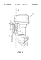
- FIG. 3 is an alternative embodiment of the present invention.
- FIG. 1 is a simplified schematic representation of a steering system made in accordance with the present invention.
- a rotary actuator 10 comprises a stator portion 12 and a rotor portion 14.
- the rotor portion 14 is rotatable relative to the stator portion 12 and the stator portion 12 is shaped to receive the rotor portion 14 in rotatable association therein.
- the rotary actuator 10 in FIG. 1 is illustrated as a hydraulic rotatable actuator. Hydraulic pressure is provided by a pump 18 with an oil reservoir 20.
- the valve 24 directs pressurized fluid from the pump 18 to either a first port 31 or second port 32.
- the reservoir 20 is connected, through valve 24, to either the first or second ports, 31 or 32, depending on the internal position of the valve components.
- valve 24 Many different types are known to those skilled in the art.
- the only limitation of the valve 24 used in conjunction with the present invention is that it must be able to take pressurized fluid from the pump 18 and direct it selectively to either the first or second ports, 31 or 32.
- the valve 24 directs pressurized fluid into the first port 31, it causes relative rotational movement between the rotor 14 and stator 12 in a first direction.
- the valve 24 causes the pressurized fluid to flow into the second port 32, the relative motion between the stator 12 and rotor 14 is reversed.
- the pump 18 draws fluid from the reservoir 20.
- valve 24 is controlled by signals received from a steering mechanism 46 of a steering wheel 48.
- Signals on lines 41 and 42 respond to the rotational position of the steering wheel 48 and determine the internal configuration of the valve 24. In turn, these signals determine whether the pressurized fluid from the pump 18 is directed to the first port 31 or the second port 32.
- the rotational position of the stator 12 with respect to the rotor 14 is determined by the rotational position of the steering wheel 48.
- FIG. 1 represents a use of a hydraulic rotary actuator 10. It should be understood that other types of rotary actuators 10 can be used in conjunction with the present invention.
- FIG. 2 shows an outboard motor 50 attached to a transom 52 of a boat.
- a first bracket 61 is attached to the outboard motor 50 and a second bracket 62 is attached to the transom 52.
- a stator portion 12 of the rotary actuator is attached to the first bracket 61 and a rotor portion 14 is attached to the second bracket 62.
- the stator portion 12 and the rotor portion 14 are rotatable relative to each other.
- FIG. 2 comprises a hydraulic rotary actuator 10 that has a first port 31 and a second port 32.
- Hoses, 71 and 72 are shown connected to the first and second ports, 31 and 32, respectively.
- the hoses, 71 and 72 are connected to a valve 24 which, in turn, is connected to a pump 18 as described above in conjunction with FIG. 1.
- the pressure can be provided to the hydraulic rotary actuator 10 through either its first or second port, 31 or 32, to selectively cause the first bracket 61 to rotate relative to the second bracket 62.
- This causes the outboard motor 50 to rotate about a generally vertical steering axis 80.
- the steering axis 80 is not precisely vertical. Since the present invention is not directly related to the tilting or trimming capabilities of the outboard motor 10, the trim system is not illustrated in FIG. 2. However, as is well known to those skilled in the art, the outboard motor 50 is generally made trimable about a trim axis that is generally horizontal and generally parallel to the surface of the transom 52. That trim axis is perpendicular to the drawing in FIG. 2.
- FIG. 3 shows an alternative embodiment of the present invention.
- the embodiment of FIG. 3 is generally similar to that of FIG. 2 except with respect to the basic connections of the rotor 14 and stator 12 portions of the hydraulic rotary actuator to the first and second brackets, 61 and 62.
- the rotor portion 14 is attached to the first bracket 61 and the stator portion 12 is attached to the second bracket 62.
- This connects the outboard motor 50 to the rotor portion 14, which is rotatable about steering axis 80 while the stator portion 12 is stationary and attached to the second bracket 62.
- the basic operation is the same as the embodiment in FIG. 2.
- the hydraulic rotary actuator 10 causes the rotor 14 to rotate relative to the stator portion 12. Steering is accomplished by a system such as that described in conjunction with FIG. 1.
- FIGS. 1, 2 and 3 illustrate two of many possible embodiments of the present invention.
- the use of a rotary actuator 10 allows the outboard motor 50 to be rotated for purposes of steering without the necessity of a plurality of hydraulic cylinders and linkages to accomplish this purpose.
- the rotary actuator can be hydraulic, as illustrated in the Figures, or can be an electrical rotary actuator as described above in conjunction with the prior art.
Abstract
Description
Claims (3)
Priority Applications (1)
| Application Number | Priority Date | Filing Date | Title |
|---|---|---|---|
| US09/327,280 US6113444A (en) | 1999-06-04 | 1999-06-04 | Steering mechanism for an outboard motor |
Applications Claiming Priority (1)
| Application Number | Priority Date | Filing Date | Title |
|---|---|---|---|
| US09/327,280 US6113444A (en) | 1999-06-04 | 1999-06-04 | Steering mechanism for an outboard motor |
Publications (1)
| Publication Number | Publication Date |
|---|---|
| US6113444A true US6113444A (en) | 2000-09-05 |
Family
ID=23275905
Family Applications (1)
| Application Number | Title | Priority Date | Filing Date |
|---|---|---|---|
| US09/327,280 Expired - Lifetime US6113444A (en) | 1999-06-04 | 1999-06-04 | Steering mechanism for an outboard motor |
Country Status (1)
| Country | Link |
|---|---|
| US (1) | US6113444A (en) |
Cited By (16)
| Publication number | Priority date | Publication date | Assignee | Title |
|---|---|---|---|---|
| US6524147B1 (en) | 2001-09-28 | 2003-02-25 | Mark X Steering Systems, Llc | Power assist marine steering system |
| US6561859B1 (en) * | 2000-07-21 | 2003-05-13 | Bombardier Motor Corporation Of America | Marine engine steering arm yoke and trunnion assembly |
| US6598553B1 (en) | 2002-02-13 | 2003-07-29 | Mark X Steering Systems, Llc | Power assist marine steering system |
| US8840439B1 (en) | 2011-05-31 | 2014-09-23 | Brp Us Inc. | Marine outboard engine having a tilt/trim and steering bracket assembly |
| US8851944B1 (en) | 2012-12-20 | 2014-10-07 | Brp Us Inc. | Marine engine hydraulic system |
| WO2015023534A1 (en) * | 2013-08-15 | 2015-02-19 | Blue Sky Marine, LLC | A hull mounted, steerable marine drive with trim actuation |
| CN104943843A (en) * | 2015-05-22 | 2015-09-30 | 武汉海王机电工程技术公司 | Mechanical full-rotating controlling handle used for ships |
| WO2016004532A1 (en) * | 2014-07-08 | 2016-01-14 | Marine Canada Acquisition Inc. | Electric actuator for a marine steering system |
| US9809289B2 (en) | 2013-08-15 | 2017-11-07 | Blue Sky Marine, LLC | Hull mounted, steerable marine drive with trim actuation |
| US9849957B1 (en) | 2015-03-31 | 2017-12-26 | Brunswick Corporation | Systems and steering actuators for steering outboard marine engines |
| US20180281915A1 (en) * | 2017-03-31 | 2018-10-04 | Steering Solutions Ip Holding Corporation | Marine power steering system |
| US10472038B1 (en) * | 2018-12-18 | 2019-11-12 | Brunswick Corporation | Hydraulic fluid reservoirs for steering actuators on outboard motors |
| US10518858B1 (en) | 2017-07-12 | 2019-12-31 | Brunswick Corporation | Systems and steering actuators for steering outboard marine engines |
| US10683073B2 (en) | 2017-08-25 | 2020-06-16 | Marine Canada Acquisition Inc. | Electric actuator for a marine steering system |
| US11173995B1 (en) | 2019-12-13 | 2021-11-16 | Brunswick Corporation | Systems and methods for preventing aeration in power steering systems for marine propulsion devices |
| US11247762B1 (en) | 2019-12-19 | 2022-02-15 | Brunswick Corporation | Systems and methods for preserving electrical power in a marine vessel having a marine propulsion device |
Citations (9)
| Publication number | Priority date | Publication date | Assignee | Title |
|---|---|---|---|---|
| US3426652A (en) * | 1965-02-02 | 1969-02-11 | William Blake & Co Inc | Rotary hydraulic actuator with locking means |
| US3587511A (en) * | 1969-04-24 | 1971-06-28 | Curt Buddrus | Hydraulic marine propulsion system |
| US3596626A (en) * | 1969-05-22 | 1971-08-03 | Curt Buddrus | Steering and tilting systems for marine vessels |
| US3673978A (en) * | 1970-08-12 | 1972-07-04 | Sperry Rand Corp | Outboard drive unit for boats |
| US3847107A (en) * | 1973-02-16 | 1974-11-12 | C Buddrus | Hydraulic marine propulsion and guidance system |
| US3915111A (en) * | 1974-10-04 | 1975-10-28 | Curt Buddrus | Hydraulic marine propulsion and guidance system |
| US4422366A (en) * | 1981-10-16 | 1983-12-27 | Weyer Paul P | Rotary helical actuator |
| US5038066A (en) * | 1990-09-12 | 1991-08-06 | General Motors Corporation | Claw pole rotary actuator with limited angular movement |
| US5702275A (en) * | 1995-09-01 | 1997-12-30 | Hundertmark; James M. | Steering mechanism |
-
1999
- 1999-06-04 US US09/327,280 patent/US6113444A/en not_active Expired - Lifetime
Patent Citations (9)
| Publication number | Priority date | Publication date | Assignee | Title |
|---|---|---|---|---|
| US3426652A (en) * | 1965-02-02 | 1969-02-11 | William Blake & Co Inc | Rotary hydraulic actuator with locking means |
| US3587511A (en) * | 1969-04-24 | 1971-06-28 | Curt Buddrus | Hydraulic marine propulsion system |
| US3596626A (en) * | 1969-05-22 | 1971-08-03 | Curt Buddrus | Steering and tilting systems for marine vessels |
| US3673978A (en) * | 1970-08-12 | 1972-07-04 | Sperry Rand Corp | Outboard drive unit for boats |
| US3847107A (en) * | 1973-02-16 | 1974-11-12 | C Buddrus | Hydraulic marine propulsion and guidance system |
| US3915111A (en) * | 1974-10-04 | 1975-10-28 | Curt Buddrus | Hydraulic marine propulsion and guidance system |
| US4422366A (en) * | 1981-10-16 | 1983-12-27 | Weyer Paul P | Rotary helical actuator |
| US5038066A (en) * | 1990-09-12 | 1991-08-06 | General Motors Corporation | Claw pole rotary actuator with limited angular movement |
| US5702275A (en) * | 1995-09-01 | 1997-12-30 | Hundertmark; James M. | Steering mechanism |
Non-Patent Citations (1)
| Title |
|---|
| Brochure of the Helac Corporation. * |
Cited By (22)
| Publication number | Priority date | Publication date | Assignee | Title |
|---|---|---|---|---|
| US6561859B1 (en) * | 2000-07-21 | 2003-05-13 | Bombardier Motor Corporation Of America | Marine engine steering arm yoke and trunnion assembly |
| US6524147B1 (en) | 2001-09-28 | 2003-02-25 | Mark X Steering Systems, Llc | Power assist marine steering system |
| US20040040485A1 (en) * | 2001-09-28 | 2004-03-04 | Mark X Steering Systems, Llc | Power assist marine steering system |
| US6598553B1 (en) | 2002-02-13 | 2003-07-29 | Mark X Steering Systems, Llc | Power assist marine steering system |
| US8840439B1 (en) | 2011-05-31 | 2014-09-23 | Brp Us Inc. | Marine outboard engine having a tilt/trim and steering bracket assembly |
| US8851944B1 (en) | 2012-12-20 | 2014-10-07 | Brp Us Inc. | Marine engine hydraulic system |
| AU2014306895B2 (en) * | 2013-08-15 | 2017-08-10 | Blue Sky Marine, LLC | A hull mounted, steerable marine drive with trim actuation |
| WO2015023534A1 (en) * | 2013-08-15 | 2015-02-19 | Blue Sky Marine, LLC | A hull mounted, steerable marine drive with trim actuation |
| US9809289B2 (en) | 2013-08-15 | 2017-11-07 | Blue Sky Marine, LLC | Hull mounted, steerable marine drive with trim actuation |
| US9266593B2 (en) | 2013-08-15 | 2016-02-23 | Blue Sky Marine, LLC | Hull mounted, steerable marine drive with trim actuation |
| US9944377B2 (en) | 2014-07-08 | 2018-04-17 | Marine Canada Acquisition Inc. | Electric actuator for a marine steering system |
| WO2016004532A1 (en) * | 2014-07-08 | 2016-01-14 | Marine Canada Acquisition Inc. | Electric actuator for a marine steering system |
| US9849957B1 (en) | 2015-03-31 | 2017-12-26 | Brunswick Corporation | Systems and steering actuators for steering outboard marine engines |
| CN104943843A (en) * | 2015-05-22 | 2015-09-30 | 武汉海王机电工程技术公司 | Mechanical full-rotating controlling handle used for ships |
| US20180281915A1 (en) * | 2017-03-31 | 2018-10-04 | Steering Solutions Ip Holding Corporation | Marine power steering system |
| US10899424B2 (en) * | 2017-03-31 | 2021-01-26 | Steering Solutions Ip Holding Corporation | Marine power steering system |
| US10518858B1 (en) | 2017-07-12 | 2019-12-31 | Brunswick Corporation | Systems and steering actuators for steering outboard marine engines |
| US10683073B2 (en) | 2017-08-25 | 2020-06-16 | Marine Canada Acquisition Inc. | Electric actuator for a marine steering system |
| US10472038B1 (en) * | 2018-12-18 | 2019-11-12 | Brunswick Corporation | Hydraulic fluid reservoirs for steering actuators on outboard motors |
| US11173995B1 (en) | 2019-12-13 | 2021-11-16 | Brunswick Corporation | Systems and methods for preventing aeration in power steering systems for marine propulsion devices |
| US11247762B1 (en) | 2019-12-19 | 2022-02-15 | Brunswick Corporation | Systems and methods for preserving electrical power in a marine vessel having a marine propulsion device |
| US11794871B1 (en) | 2019-12-19 | 2023-10-24 | Brunswick Corporation | Systems and methods for preserving electrical power in a marine vessel having a marine propulsion device |
Similar Documents
| Publication | Publication Date | Title |
|---|---|---|
| US6113444A (en) | Steering mechanism for an outboard motor | |
| FI108119B (en) | Turning a propulsion unit | |
| US7267588B1 (en) | Selectively lockable marine propulsion devices | |
| US5016553A (en) | Vector steering control system | |
| US7485018B2 (en) | Marine drive system | |
| US7131385B1 (en) | Method for braking a vessel with two marine propulsion devices | |
| FI107042B (en) | Turning a propulsion unit | |
| US7255616B1 (en) | Steering system for a marine propulsion device | |
| US7699674B1 (en) | Actuator for a marine steering system | |
| US3847107A (en) | Hydraulic marine propulsion and guidance system | |
| US4744777A (en) | Power steering system for marine propulsion device | |
| US3901177A (en) | Marine propulsion apparatus | |
| US6454620B1 (en) | Integrated external hydraulic trimming and steering system for an extended sterndrive transom assembly | |
| US4576581A (en) | Reversible Magnus propeller | |
| US3596626A (en) | Steering and tilting systems for marine vessels | |
| JPH08324495A (en) | Power steering assisting device | |
| US5167548A (en) | Trimming system for boat propulsion system | |
| US3874321A (en) | Boat steering and reversing system | |
| US5249992A (en) | Marine propulsion unit with controlled cyclic and collective blade pitch | |
| US4919630A (en) | Inboard drive system for a marine craft | |
| EP0102579A2 (en) | Electro-hydraulic steering gear for watercraft | |
| KR0185190B1 (en) | Steering mechanism in a boat propulsion system | |
| US7104853B1 (en) | Marine gimbal outdrive assembly | |
| US4641599A (en) | Speed maneuvering water craft and controls | |
| US10479469B2 (en) | Steering system for an outboard motor |
Legal Events
| Date | Code | Title | Description |
|---|---|---|---|
| AS | Assignment |
Owner name: BRUNSWICK CORPORATION, ILLINOIS Free format text: ASSIGNMENT OF ASSIGNORS INTEREST;ASSIGNOR:RITGER, BERNARD E.;REEL/FRAME:010030/0841 Effective date: 19990603 |
|
| STCF | Information on status: patent grant |
Free format text: PATENTED CASE |
|
| FPAY | Fee payment |
Year of fee payment: 4 |
|
| FPAY | Fee payment |
Year of fee payment: 8 |
|
| AS | Assignment |
Owner name: JPMORGAN CHASE BANK, N.A., TEXAS Free format text: SECURITY AGREEMENT;ASSIGNORS:BRUNSWICK CORPORATION;TRITON BOAT COMPANY, L.P.;ATTWOOD CORPORATION;AND OTHERS;REEL/FRAME:022092/0365 Effective date: 20081219 Owner name: JPMORGAN CHASE BANK, N.A.,TEXAS Free format text: SECURITY AGREEMENT;ASSIGNORS:BRUNSWICK CORPORATION;TRITON BOAT COMPANY, L.P.;ATTWOOD CORPORATION;AND OTHERS;REEL/FRAME:022092/0365 Effective date: 20081219 |
|
| AS | Assignment |
Owner name: THE BANK OF NEW YORK MELLON TRUST COMPANY, N.A., I Free format text: SECURITY AGREEMENT;ASSIGNORS:BRUNSWICK CORPORATION;ATTWOOD CORPORATION;BOSTON WHALER, INC.;AND OTHERS;REEL/FRAME:023180/0493 Effective date: 20090814 Owner name: THE BANK OF NEW YORK MELLON TRUST COMPANY, N.A.,IL Free format text: SECURITY AGREEMENT;ASSIGNORS:BRUNSWICK CORPORATION;ATTWOOD CORPORATION;BOSTON WHALER, INC.;AND OTHERS;REEL/FRAME:023180/0493 Effective date: 20090814 |
|
| AS | Assignment |
Owner name: LAND 'N' SEA DISTRIBUTING, INC., FLORIDA Free format text: RELEASE BY SECURED PARTY;ASSIGNOR:JPMORGAN CHASE BANK, N.A., AS ADMINISTRATIVE AGENT;REEL/FRAME:026026/0001 Effective date: 20110321 Owner name: BRUNSWICK COMMERICAL & GOVERNMENT PRODUCTS, INC., Free format text: RELEASE BY SECURED PARTY;ASSIGNOR:JPMORGAN CHASE BANK, N.A., AS ADMINISTRATIVE AGENT;REEL/FRAME:026026/0001 Effective date: 20110321 Owner name: BRUNSWICK BOWLING & BILLIARDS CORPORATION, ILLINOI Free format text: RELEASE BY SECURED PARTY;ASSIGNOR:JPMORGAN CHASE BANK, N.A., AS ADMINISTRATIVE AGENT;REEL/FRAME:026026/0001 Effective date: 20110321 Owner name: BRUNSWICK FAMILY BOAT CO. INC., WASHINGTON Free format text: RELEASE BY SECURED PARTY;ASSIGNOR:JPMORGAN CHASE BANK, N.A., AS ADMINISTRATIVE AGENT;REEL/FRAME:026026/0001 Effective date: 20110321 Owner name: BOSTON WHALER, INC., FLORIDA Free format text: RELEASE BY SECURED PARTY;ASSIGNOR:JPMORGAN CHASE BANK, N.A., AS ADMINISTRATIVE AGENT;REEL/FRAME:026026/0001 Effective date: 20110321 Owner name: BRUNSWICK CORPORATION, ILLINOIS Free format text: RELEASE BY SECURED PARTY;ASSIGNOR:JPMORGAN CHASE BANK, N.A., AS ADMINISTRATIVE AGENT;REEL/FRAME:026026/0001 Effective date: 20110321 Owner name: ATTWOOD CORPORATION, MICHIGAN Free format text: RELEASE BY SECURED PARTY;ASSIGNOR:JPMORGAN CHASE BANK, N.A., AS ADMINISTRATIVE AGENT;REEL/FRAME:026026/0001 Effective date: 20110321 Owner name: BRUNSWICK LEISURE BOAT COMPANY, LLC, INDIANA Free format text: RELEASE BY SECURED PARTY;ASSIGNOR:JPMORGAN CHASE BANK, N.A., AS ADMINISTRATIVE AGENT;REEL/FRAME:026026/0001 Effective date: 20110321 Owner name: TRITON BOAT COMPANY, L.P., TENNESSEE Free format text: RELEASE BY SECURED PARTY;ASSIGNOR:JPMORGAN CHASE BANK, N.A., AS ADMINISTRATIVE AGENT;REEL/FRAME:026026/0001 Effective date: 20110321 Owner name: LUND BOAT COMPANY, MINNESOTA Free format text: RELEASE BY SECURED PARTY;ASSIGNOR:JPMORGAN CHASE BANK, N.A., AS ADMINISTRATIVE AGENT;REEL/FRAME:026026/0001 Effective date: 20110321 |
|
| AS | Assignment |
Owner name: JPMORGAN CHASE BANK, N.A., AS ADMINISTRATIVE AGENT Free format text: SECURITY AGREEMENT;ASSIGNORS:BRUNSWICK CORPORATION;ATTWOOD CORPORATION;BOSTON WHALER, INC.;AND OTHERS;REEL/FRAME:026072/0239 Effective date: 20110321 |
|
| FPAY | Fee payment |
Year of fee payment: 12 |
|
| AS | Assignment |
Owner name: BRUNSWICK CORPORATION, ILLINOIS Free format text: RELEASE BY SECURED PARTY;ASSIGNOR:THE BANK OF NEW YORK MELLON;REEL/FRAME:031973/0242 Effective date: 20130717 |
|
| AS | Assignment |
Owner name: LAND 'N' SEA DISTRIBUTING, INC., ILLINOIS Free format text: RELEASE BY SECURED PARTY;ASSIGNOR:JPMORGAN CHASE BANK, N.A.;REEL/FRAME:034794/0300 Effective date: 20141226 Owner name: LUND BOAT COMPANY, ILLINOIS Free format text: RELEASE BY SECURED PARTY;ASSIGNOR:JPMORGAN CHASE BANK, N.A.;REEL/FRAME:034794/0300 Effective date: 20141226 Owner name: BOSTON WHALER, INC., ILLINOIS Free format text: RELEASE BY SECURED PARTY;ASSIGNOR:JPMORGAN CHASE BANK, N.A.;REEL/FRAME:034794/0300 Effective date: 20141226 Owner name: BRUNSWICK COMMERCIAL & GOVERNMENT PRODUCTS, INC., Free format text: RELEASE BY SECURED PARTY;ASSIGNOR:JPMORGAN CHASE BANK, N.A.;REEL/FRAME:034794/0300 Effective date: 20141226 Owner name: BRUNSWICK BOWLING & BILLIARDS CORPORATION, ILLINOI Free format text: RELEASE BY SECURED PARTY;ASSIGNOR:JPMORGAN CHASE BANK, N.A.;REEL/FRAME:034794/0300 Effective date: 20141226 Owner name: BRUNSWICK CORPORATION, ILLINOIS Free format text: RELEASE BY SECURED PARTY;ASSIGNOR:JPMORGAN CHASE BANK, N.A.;REEL/FRAME:034794/0300 Effective date: 20141226 Owner name: ATTWOOD CORPORATION, ILLINOIS Free format text: RELEASE BY SECURED PARTY;ASSIGNOR:JPMORGAN CHASE BANK, N.A.;REEL/FRAME:034794/0300 Effective date: 20141226 Owner name: BRUNSWICK LEISURE BOAT COMPANY, LLC, ILLINOIS Free format text: RELEASE BY SECURED PARTY;ASSIGNOR:JPMORGAN CHASE BANK, N.A.;REEL/FRAME:034794/0300 Effective date: 20141226 Owner name: BRUNSWICK FAMILY BOAT CO. INC., ILLINOIS Free format text: RELEASE BY SECURED PARTY;ASSIGNOR:JPMORGAN CHASE BANK, N.A.;REEL/FRAME:034794/0300 Effective date: 20141226 |