US6098459A - Method of producing a sensor subassembly, and sensor subassembly - Google Patents

Method of producing a sensor subassembly, and sensor subassembly Download PDF

Info

Publication number
US6098459A
US6098459A US09/426,419 US42641999A US6098459A US 6098459 A US6098459 A US 6098459A US 42641999 A US42641999 A US 42641999A US 6098459 A US6098459 A US 6098459A
Authority
US
United States
Prior art keywords
sensor
base part
circuit board
printed circuit
plastic base
Prior art date
Legal status (The legal status is an assumption and is not a legal conclusion. Google has not performed a legal analysis and makes no representation as to the accuracy of the status listed.)
Expired - Fee Related
Application number
US09/426,419
Inventor
Hans-Peter Bauer
Current Assignee (The listed assignees may be inaccurate. Google has not performed a legal analysis and makes no representation or warranty as to the accuracy of the list.)
Siemens AG
Original Assignee
Siemens AG
Priority date (The priority date is an assumption and is not a legal conclusion. Google has not performed a legal analysis and makes no representation as to the accuracy of the date listed.)
Filing date
Publication date
Application filed by Siemens AG filed Critical Siemens AG
Assigned to SIEMENS AKTIENGESELLSCHAFT reassignment SIEMENS AKTIENGESELLSCHAFT ASSIGNMENT OF ASSIGNORS INTEREST (SEE DOCUMENT FOR DETAILS). Assignors: BAUER, HANS-PETER
Application granted granted Critical
Publication of US6098459A publication Critical patent/US6098459A/en
Anticipated expiration legal-status Critical
Expired - Fee Related legal-status Critical Current

Links

Images

Classifications

    • BPERFORMING OPERATIONS; TRANSPORTING
    • B60VEHICLES IN GENERAL
    • B60RVEHICLES, VEHICLE FITTINGS, OR VEHICLE PARTS, NOT OTHERWISE PROVIDED FOR
    • B60R16/00Electric or fluid circuits specially adapted for vehicles and not otherwise provided for; Arrangement of elements of electric or fluid circuits specially adapted for vehicles and not otherwise provided for
    • B60R16/02Electric or fluid circuits specially adapted for vehicles and not otherwise provided for; Arrangement of elements of electric or fluid circuits specially adapted for vehicles and not otherwise provided for electric constitutive elements
    • B60R16/023Electric or fluid circuits specially adapted for vehicles and not otherwise provided for; Arrangement of elements of electric or fluid circuits specially adapted for vehicles and not otherwise provided for electric constitutive elements for transmission of signals between vehicle parts or subsystems
    • B60R16/0239Electronic boxes
    • GPHYSICS
    • G01MEASURING; TESTING
    • G01PMEASURING LINEAR OR ANGULAR SPEED, ACCELERATION, DECELERATION, OR SHOCK; INDICATING PRESENCE, ABSENCE, OR DIRECTION, OF MOVEMENT
    • G01P1/00Details of instruments
    • G01P1/02Housings
    • G01P1/023Housings for acceleration measuring devices
    • HELECTRICITY
    • H05ELECTRIC TECHNIQUES NOT OTHERWISE PROVIDED FOR
    • H05KPRINTED CIRCUITS; CASINGS OR CONSTRUCTIONAL DETAILS OF ELECTRIC APPARATUS; MANUFACTURE OF ASSEMBLAGES OF ELECTRICAL COMPONENTS
    • H05K5/00Casings, cabinets or drawers for electric apparatus
    • H05K5/0026Casings, cabinets or drawers for electric apparatus provided with connectors and printed circuit boards [PCB], e.g. automotive electronic control units
    • H05K5/0078Casings, cabinets or drawers for electric apparatus provided with connectors and printed circuit boards [PCB], e.g. automotive electronic control units specially adapted for acceleration sensors, e.g. crash sensors, airbag sensors

Definitions

  • the invention relates to a sensor subassembly and to a method of producing the sensor subassembly.
  • Such sensor subassemblies are used, in particular, in occupant protection systems of motor vehicles.
  • Sensor subassemblies containing sensors should be capable of cost-effective production and should supply precise, reliable output signals for the circuits connected downstream of the controller. Simple mounting of the sensor or of the sensor subassembly provided with the sensor is a further important requirement.
  • sensor subassemblies When such sensor subassemblies are used in occupant protection systems of motor vehicles, it is usually the acceleration of an inertial mass contained in the sensor element which is measured or, in particular in side impact protection devices, a pressure wave is registered which, for example, originates from sudden deformation of an outer panel of a door.
  • the sensor subassembly has a base part made of plastic, which is injection-molded around a punched grid. Sensor connections of a punched grid end within a sensor holding region formed by a hole in the base part. Towards one end, the base part is configured as a plug, from which ends of the punched grid project as plug connections.
  • a sensor element is fastened to a supporting part that consists of plastic, which can be inserted into the hole-like sensor holding region and is electrically connected to the sensor connections, for example by use of a bonding.
  • a further component, which engages over the sensor is subsequently clipped to the base part.
  • the invention is further based on the object of providing a sensor subassembly that can be produced cost-effectively in large numbers, can be adapted to the different requirements and has a high reliability.
  • a method of producing a sensor subassembly which includes producing a plastic base part having a sensor holding region and a connection region; fastening a printed circuit board to the plastic base part; fitting a sensor element to the plastic base part and providing sensor connections for producing an electrical connection between the sensor element and the printed circuit board; and placing plug connections that extend from the connection region to the printed circuit board for providing an electrical connection between the printed circuit board and the plug connections.
  • a significant feature of the method according to the invention is based on the fact that a printed circuit board is fastened to the finished base part. It being possible for the printed circuit board to be equipped to correspond to the respective requirements, so that, in spite of different sensor elements and printed circuit boards with different equipment or different configurations, the same base part can be used in large numbers for the different configurations.
  • the tolerances on the sensor subassembly are reduced to a minimum by the prefabricated base part having the sensor holding region and the connection region.
  • the finished, equipped printed circuit board is fastened to the base part, so that the sensor subassembly can be used as a satellite in a complex circuit.
  • the plug connections are advantageously cast into the base part during production of the latter. It goes without saying that pressing or any other suitable fastening is also possible.
  • the simple fitting of the sensor element and its electrical connection are provided by the configuration of the base part.
  • the sensor subassembly which is compact and, if appropriate, hermetically sealed, and in which only the plug connections and, if necessary, a channel to the sensor element, are free to the outside, it being possible for the channel to be provided, for example, when the sensor element is a pressure-sensitive sensor element.
  • a diaphragm can additionally be provided directly over the sensor element.
  • the printed circuit board can contain the entire drive and/or evaluation circuit for the sensor element provides a cost-effective and, at the same time, functionally reliable sensor subassembly, which reduces the requirements on the further circuit environment.
  • the invention In addition to the ability of the sensor subassembly to be produced simply and with accurate tolerances, numerous further advantages are achieved by the invention. For example, if the sensor element is sensitive to acceleration, precise transmission of movement from a component, to which the base part is fastened, to the sensor element itself, is achieved. The transmission of movement includes only the interfaces between the component whose acceleration is to be measured and the base part (and, if appropriate, its covering), and between the base part and the sensor element. This leads to a very good and well-defined measuring sensitivity.
  • FIG. 1 is a diagrammatic, exploded, perspective view of components of a sensor subassembly
  • FIGS. 2 to 4 are perspective views of various stages in the production of the sensor subassembly.
  • FIG. 5 is a perspective view of the finished, encapsulated sensor subassembly.
  • FIG. 1 there is shown a base part 2 which consists of plastic and forms a frame for an entire sensor subassembly and, for example, is injection-molded.
  • a base part 2 which consists of plastic and forms a frame for an entire sensor subassembly and, for example, is injection-molded.
  • connection region 6 which forms a sleeve for the insertion of a plug
  • sensor holding region 8 which is formed with a recess 10.
  • the base part 2 also has recesses 11 to hold a printed circuit board 18 which is described later.
  • a non-illustrated rear wall of the connection region 6 also has holes.
  • the subassembly also includes connecting pins 13 and 14 which, in order to be handled more easily, are initially supplied as a punched grid structure.
  • a sensor element 16 which can be formed as a chip having electrical contacts that are exposed to the outside but not visible, is further provided.
  • the sensor element 16 can respond, for example, to pressure changes or to accelerations.
  • an acceleration sensor 16 it contains for example a seismic, inertial mass, whose deflections are registered.
  • a pressure sensor 16 it contains for example a pressure-sensitive element, such as a piezo-electric element, a diaphragm and so on.
  • the printed circuit board 18 that, on its rear side, is equipped with electronic components that form a drive circuit 30 and/or an evaluation circuit 35 for the sensor element 16.
  • the printed circuit board 18 is provided with holes 20, into which the connecting pins 13, 14 can be introduced and where they can be connected electrically, for example by soldering.
  • the connecting pins 13 and 14 are pressed into the holes provided for this in the base part 2.
  • the connecting pins 13 can also be introduced directly into the mold during the injection molding of the base part 2, so that they are integrated into the base part 2 directly during the injection molding of the latter.
  • Those regions of the connecting pins 13 which project into the recess 10 form sensor connections for making electrical contact with the sensor element 16.
  • Those regions of the connecting pins 14 that project into the connection region 6 can form the plug connections directly.
  • the sensor element 16 is introduced into the recess 10 and, for example, adhesively bonded to a bottom of the recess 10.
  • the configuration of the sensor element 16 in the recess 10 is carried out in a geometrically well-defined manner, by the bottom of the recess 10 being provided with an appropriate cutout or by non-illustrated webs which position the sensor element 16 being formed within the recess 10.
  • the non-illustrated electrical contacts of the sensor element 16 are then soldered directly to the connecting pins 13 or bonded by wires.
  • the printed circuit board 18 is introduced from below into the base part 2.
  • the base part 2 and the printed circuit board 18 can be provided with latching devices for mutual latching.
  • the sensor element 16 is then connected to the printed circuit board 18 via the connecting pins 13.
  • the printed circuit board 18 is connected via the connecting pins 14 to the plug connections (formed, for example, by the free ends of the connecting pins 14) which project into the interior of the connection region 6 but are not visible in FIG. 5.
  • the entire subassembly is provided with a covering 22 (shown by dashed lines) in an injection-molding or casting operation, access to the connection region 6 and advantageously also the fastening eyes 4 remaining free.
  • a channel 24 to a pressure-sensitive region of the sensor element 16 or to the entire sensor element 16 remains free, in order to apply to the latter the pressure to be measured.
  • the entire subassembly is hermetically sealed off from the outside by the covering 22 and is intrinsically extremely rugged.
  • the entire sensor subassembly can be screwed directly onto a component whose acceleration or whose vibration behavior, for example, is to be measured.
  • the measurement is very precise, since the vibrations have to pass only through the interface between the component to be measured (not illustrated) and the base part 2 and the interface between the base part 2 and the sensor element 16.
  • the senor element 16 can be fastened merely by being soldered to the connecting pins 13.
  • the printed circuit board 18 can additionally be adhesively bonded to the base part 2.
  • the recess can be free of the covering 22 in the region of the sensor element 16 and can be closed by a cover, so that the sensor element 16 is accessible, for example for replacement.
  • the printed circuit board can be configured as a punched grid (lead frame).

Abstract

A sensor subassembly contains a base part that is formed of plastic and has a sensor holding region with sensor connections provided therein and a connection region with plug connections provided therein. A sensor element with electrical contacts is electrically conductively connected to the sensor connections. Fastened to the base part is a printed circuit board, via which an electrical connection between the sensor element and the plug connections is made.

Description

CROSS-REFERENCE TO RELATED APPLICATION
This application is a continuation of copending International Application PCT/DE98/01130, filed Apr. 22, 1998, which designated the United States.
BACKGROUND OF THE INVENTION Field of the Invention
The invention relates to a sensor subassembly and to a method of producing the sensor subassembly. Such sensor subassemblies are used, in particular, in occupant protection systems of motor vehicles.
With the increasing use of electronic controllers and regulators, increasing importance is attached to the sensors. Sensor subassemblies containing sensors should be capable of cost-effective production and should supply precise, reliable output signals for the circuits connected downstream of the controller. Simple mounting of the sensor or of the sensor subassembly provided with the sensor is a further important requirement. When such sensor subassemblies are used in occupant protection systems of motor vehicles, it is usually the acceleration of an inertial mass contained in the sensor element which is measured or, in particular in side impact protection devices, a pressure wave is registered which, for example, originates from sudden deformation of an outer panel of a door.
Published, European Patent Application EP 0 297 961 A2 shows a sensor subassembly of the generic type whose sensor element responds to pressure. The sensor subassembly has a base part made of plastic, which is injection-molded around a punched grid. Sensor connections of a punched grid end within a sensor holding region formed by a hole in the base part. Towards one end, the base part is configured as a plug, from which ends of the punched grid project as plug connections. A sensor element is fastened to a supporting part that consists of plastic, which can be inserted into the hole-like sensor holding region and is electrically connected to the sensor connections, for example by use of a bonding. A further component, which engages over the sensor, is subsequently clipped to the base part. Overall the sensor subassembly is of relatively complicated construction. Before the evaluation of output signals from the sensor element which are picked off via the plug connections, a further device is needed for processing the signals in an EDP-suitable form, since signal processing directly on the sensor subassembly is not provided. Published, European Patent Application EP 0 566 758 A1 discloses a sensor subassembly whose sensor element is sensitive to acceleration. The sensor element is soldered to a printed circuit board by connecting legs and is additionally held on holding arms that are connected to the printed circuit board. The printed circuit board is disposed within a housing having insulating material which protects the sensor element from extremely hard impacts being disposed between the printed circuit board and the housing, and between the sensor element and the housing. The construction of this known sensor unit is also relatively complicated.
SUMMARY OF THE INVENTION
It is accordingly an object of the invention to provide a method of producing a sensor subassembly, and a sensor subassembly which overcome the above-mentioned disadvantages the prior art methods and devices of this general type, in particular a sensor subassembly which can be used in occupant protection systems of motor vehicles, which, with the capability of simple implementation, permits the costeffective production of sensor subassemblies which can be adapted to different requirements and operate reliably.
The invention is further based on the object of providing a sensor subassembly that can be produced cost-effectively in large numbers, can be adapted to the different requirements and has a high reliability.
With the foregoing and other objects in view there is provided, in accordance with the invention, a method of producing a sensor subassembly, which includes producing a plastic base part having a sensor holding region and a connection region; fastening a printed circuit board to the plastic base part; fitting a sensor element to the plastic base part and providing sensor connections for producing an electrical connection between the sensor element and the printed circuit board; and placing plug connections that extend from the connection region to the printed circuit board for providing an electrical connection between the printed circuit board and the plug connections.
A significant feature of the method according to the invention is based on the fact that a printed circuit board is fastened to the finished base part. It being possible for the printed circuit board to be equipped to correspond to the respective requirements, so that, in spite of different sensor elements and printed circuit boards with different equipment or different configurations, the same base part can be used in large numbers for the different configurations. The tolerances on the sensor subassembly are reduced to a minimum by the prefabricated base part having the sensor holding region and the connection region.
According to another embodiment of the invention, the finished, equipped printed circuit board is fastened to the base part, so that the sensor subassembly can be used as a satellite in a complex circuit.
According to a further embodiment of the invention, the plug connections are advantageously cast into the base part during production of the latter. It goes without saying that pressing or any other suitable fastening is also possible.
According to an additional embodiment of the invention, the simple fitting of the sensor element and its electrical connection are provided by the configuration of the base part.
According to yet another embodiment of the invention, the advantage that accelerations which act on the base part are transmitted directly to the sensor element, since the latter is virtually formed in one piece with the base part as a result of the adhesive bonding, is achieved.
According to yet a further embodiment, it is advantageous for recesses that fix the printed circuit board geometrically to be provided on the base part.
According to an added feature of the invention, the sensor subassembly which is compact and, if appropriate, hermetically sealed, and in which only the plug connections and, if necessary, a channel to the sensor element, are free to the outside, it being possible for the channel to be provided, for example, when the sensor element is a pressure-sensitive sensor element. It goes without saying that a diaphragm can additionally be provided directly over the sensor element. The fact that the geometric configuration between the plug connections and the sensor element is defined directly by the base part results in that the injection mold, in which a channel to the sensor element and the access to the plug connections has to remain free, can be produced with very accurate tolerances. In this way, a satisfactory quality of the completely ready-to-mount and sealed sensor subassembly is obtained.
The fact that the printed circuit board can contain the entire drive and/or evaluation circuit for the sensor element provides a cost-effective and, at the same time, functionally reliable sensor subassembly, which reduces the requirements on the further circuit environment.
In addition to the ability of the sensor subassembly to be produced simply and with accurate tolerances, numerous further advantages are achieved by the invention. For example, if the sensor element is sensitive to acceleration, precise transmission of movement from a component, to which the base part is fastened, to the sensor element itself, is achieved. The transmission of movement includes only the interfaces between the component whose acceleration is to be measured and the base part (and, if appropriate, its covering), and between the base part and the sensor element. This leads to a very good and well-defined measuring sensitivity.
Other features which are considered as characteristic for the invention are set forth in the appended claims.
Although the invention is illustrated and described herein as embodied in a method of producing a sensor subassembly, and a sensor subassembly, it is nevertheless not intended to be limited to the details shown, since various modifications and structural changes may be made therein without departing from the spirit of the invention and within the scope and range of equivalents of the claims.
The construction and method of operation of the invention, however, together with additional objects and advantages thereof will be best understood from the following description of specific embodiments when read in connection with the accompanying drawings.
BRIEF DESCRIPTION OF THE DRAWINGS
FIG. 1 is a diagrammatic, exploded, perspective view of components of a sensor subassembly;
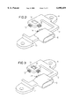
FIGS. 2 to 4 are perspective views of various stages in the production of the sensor subassembly; and
FIG. 5 is a perspective view of the finished, encapsulated sensor subassembly.
DESCRIPTION OF THE PREFERRED EMBODIMENTS
In all the figures of the drawing, sub-features and integral parts that correspond to one another bear the same reference symbol in each case. Referring now to the figures of the drawing in detail and first, particularly, to FIG. 1 thereof, there is shown a base part 2 which consists of plastic and forms a frame for an entire sensor subassembly and, for example, is injection-molded. Provided on the base part 2 are fastening eyes 4, as well as a connection region 6, which forms a sleeve for the insertion of a plug, and a sensor holding region 8 which is formed with a recess 10. The base part 2 also has recesses 11 to hold a printed circuit board 18 which is described later.
Provided on the sensor holding region 8 are holes 12. A non-illustrated rear wall of the connection region 6 also has holes.
The subassembly also includes connecting pins 13 and 14 which, in order to be handled more easily, are initially supplied as a punched grid structure. A sensor element 16, which can be formed as a chip having electrical contacts that are exposed to the outside but not visible, is further provided. The sensor element 16 can respond, for example, to pressure changes or to accelerations. As an acceleration sensor 16, it contains for example a seismic, inertial mass, whose deflections are registered. As a pressure sensor 16, it contains for example a pressure-sensitive element, such as a piezo-electric element, a diaphragm and so on.
Also provided is the printed circuit board 18 that, on its rear side, is equipped with electronic components that form a drive circuit 30 and/or an evaluation circuit 35 for the sensor element 16. The printed circuit board 18 is provided with holes 20, into which the connecting pins 13, 14 can be introduced and where they can be connected electrically, for example by soldering.
The assembly of the components illustrated in FIG. 1 takes place as described now below.
According to FIG. 2, in a first method step the connecting pins 13 and 14 are pressed into the holes provided for this in the base part 2. Alternatively, the connecting pins 13 can also be introduced directly into the mold during the injection molding of the base part 2, so that they are integrated into the base part 2 directly during the injection molding of the latter. Those regions of the connecting pins 13 which project into the recess 10 form sensor connections for making electrical contact with the sensor element 16. Those regions of the connecting pins 14 that project into the connection region 6 can form the plug connections directly.
In a subsequent method step (FIG. 3), the sensor element 16 is introduced into the recess 10 and, for example, adhesively bonded to a bottom of the recess 10. It goes without saying that the configuration of the sensor element 16 in the recess 10 is carried out in a geometrically well-defined manner, by the bottom of the recess 10 being provided with an appropriate cutout or by non-illustrated webs which position the sensor element 16 being formed within the recess 10. The non-illustrated electrical contacts of the sensor element 16 are then soldered directly to the connecting pins 13 or bonded by wires.
In a next method step (FIG. 4), the printed circuit board 18 is introduced from below into the base part 2. The underside (not visible) of the base part 2 with the appropriate recesses 11 forming guide and supporting surfaces which ensure that the free ends of the connecting pins 13.project into holes 20 in the printed circuit board 18 and can be soldered from the rear to conductor tracks of the printed circuit board 18 or pressed into the latter. It goes without saying that the base part 2 and the printed circuit board 18 can be provided with latching devices for mutual latching.
The sensor element 16 is then connected to the printed circuit board 18 via the connecting pins 13. The printed circuit board 18 is connected via the connecting pins 14 to the plug connections (formed, for example, by the free ends of the connecting pins 14) which project into the interior of the connection region 6 but are not visible in FIG. 5. In a final method step (FIG. 5), the entire subassembly is provided with a covering 22 (shown by dashed lines) in an injection-molding or casting operation, access to the connection region 6 and advantageously also the fastening eyes 4 remaining free. If the sensor element 16 is pressure-sensitive, a channel 24 to a pressure-sensitive region of the sensor element 16 or to the entire sensor element 16 remains free, in order to apply to the latter the pressure to be measured.
Otherwise, the entire subassembly is hermetically sealed off from the outside by the covering 22 and is intrinsically extremely rugged.
During the injection molding or the encapsulation, there is a unique correspondence between the channel 24, if present, and that region of the connection region 6 which remains free, since the geometry is exclusively determined by the base part 2. This ensures a satisfactory quality of the sensor subassembly. Furthermore, the subassembly is provided with all the necessary electronics, so that a plug that can be inserted into the connection region 6 is used only for the power supply and for the connection of already processed output signals to an electronic controller, for example.
Via the fastening eyes 4, the entire sensor subassembly can be screwed directly onto a component whose acceleration or whose vibration behavior, for example, is to be measured. The measurement is very precise, since the vibrations have to pass only through the interface between the component to be measured (not illustrated) and the base part 2 and the interface between the base part 2 and the sensor element 16.
It goes without saying that numerous modifications are possible. For instance, the sensor element 16 can be fastened merely by being soldered to the connecting pins 13.
Furthermore, the printed circuit board 18 can additionally be adhesively bonded to the base part 2. The recess can be free of the covering 22 in the region of the sensor element 16 and can be closed by a cover, so that the sensor element 16 is accessible, for example for replacement. The printed circuit board can be configured as a punched grid (lead frame).

Claims (14)

I claim:
1. A method of producing a sensor subassembly, which comprises:
producing a plastic base part having a sensor holding region and a connection region;
fastening a printed circuit board to the plastic base part;
fitting a sensor element to the plastic base part and providing sensor connections for producing an electrical connection between the sensor element and the printed circuit board; and
placing plug connections that extend from the connection region to the printed circuit board for providing an electrical connection between the printed circuit board and the plug connections.
2. The method according to claim 1, which comprises equipping the printed circuit board with at least one of a drive circuit and an evaluation circuit for controlling and evaluating the sensor element before the printed circuit board is fitted to the plastic base part.
3. The method according to claim 1, which comprises casting the plug connections into the plastic base part during the step of producing the plastic base part.
4. The method according to claim 1, which comprises fitting the sensor connections to the plastic base part and producing an electrical connection between the sensor element and the sensor connections and between the sensor connections and the printed circuit board.
5. The method according to claim 4, which comprises casting the sensor connections into the plastic base part during the step of producing the plastic base part.
6. The method according to claim 1, which comprises using an adhesive bonding for fastening the sensor element to the plastic base part.
7. The method according to claim 1, which comprises inserting the printed circuit board into recesses provided on the plastic base part.
8. The method according to claim 1, which comprises encapsulating the plastic base part, the printed circuit board and the sensor element with a plastic applied by injection molding but leaving free the plug connections within the connection region.
9. The method according to claim 1, which comprises encapsulating the plastic base part, the printed circuit board and the sensor element with a plastic applied by injection molding but leaving free the plug connections within the connection region and a channel to the sensor element.
10. A sensor subassembly, comprising:
a plastic base part having a sensor holding region and a connection region;
sensor connections disposed and held in said plastic base part in said sensor holding region;
plug connections disposed and held in said plastic base part in said connection region;
a sensor element with electrical contacts electrically conductively connected to said sensor connections; and
a printed circuit board fastened to said plastic base part and making an electrical connection between said sensor element and said plug connections.
11. The sensor subassembly according to claim 10, wherein said sensor element contains an acceleration sensor and is fastened directly to said plastic base part.
12. The sensor subassembly according to claim 10, wherein said printed circuit board contains at least one of a drive circuit and an evaluation circuit for driving and evaluating said sensor element.
13. The sensor subassembly according to claim 10, including a covering formed by encapsulating said plastic base part, said printed circuit board and said sensor element with plastic applied by injection molding, said covering not enclosing said plug connections within said connection region.
14. The sensor subassembly according to claim 10, including a covering formed by encapsulating said plastic base part, said printed circuit board and said sensor element with plastic applied by injection molding, said covering not enclosing said plug connections within said connection region and a channel formed therein to said sensor element.
US09/426,419 1997-04-24 1999-10-25 Method of producing a sensor subassembly, and sensor subassembly Expired - Fee Related US6098459A (en)

Applications Claiming Priority (3)

Application Number Priority Date Filing Date Title
DE19717348A DE19717348A1 (en) 1997-04-24 1997-04-24 Method of manufacturing a sensor assembly and sensor assembly
DE19717348 1997-04-24
PCT/DE1998/001130 WO1998048257A1 (en) 1997-04-24 1998-04-22 Method for producing a sensor module, and corresponding sensor module

Related Parent Applications (1)

Application Number Title Priority Date Filing Date
PCT/DE1998/001130 Continuation WO1998048257A1 (en) 1997-04-24 1998-04-22 Method for producing a sensor module, and corresponding sensor module

Publications (1)

Publication Number Publication Date
US6098459A true US6098459A (en) 2000-08-08

Family

ID=7827637

Family Applications (1)

Application Number Title Priority Date Filing Date
US09/426,419 Expired - Fee Related US6098459A (en) 1997-04-24 1999-10-25 Method of producing a sensor subassembly, and sensor subassembly

Country Status (4)

Country Link
US (1) US6098459A (en)
EP (1) EP0977979B1 (en)
DE (2) DE19717348A1 (en)
WO (1) WO1998048257A1 (en)

Cited By (5)

* Cited by examiner, † Cited by third party
Publication number Priority date Publication date Assignee Title
US20060166519A1 (en) * 2005-01-25 2006-07-27 Borgwarner Inc. Control and interconnection system for an apparatus
US20080030973A1 (en) * 2006-08-07 2008-02-07 Trw Automotive Gmbh Method for the production of a sensor and sensor
CN104204758A (en) * 2012-03-27 2014-12-10 罗伯特·博世有限公司 Support unit for a circuit board in a sensor unit and corresponding sensor unit
US10089454B2 (en) 2012-06-22 2018-10-02 Microsoft Technology Licensing, Llc Enhanced accuracy of user presence status determination
US10928241B2 (en) 2016-03-30 2021-02-23 Vitesco Technologies GmbH Ultrasound sensor

Families Citing this family (13)

* Cited by examiner, † Cited by third party
Publication number Priority date Publication date Assignee Title
DE19955603C1 (en) * 1999-11-18 2001-02-15 Siemens Ag Integrated control device for motor vehicle especially for automatic transmission
DE10000350A1 (en) * 2000-01-07 2001-07-12 Kostal Leopold Gmbh & Co Kg Sensor module for electric plug housing, includes sensor element and carrier element for holding sensor element, and contact for electrical connection to sensor
JP4297637B2 (en) * 2001-10-01 2009-07-15 株式会社デンソー Electronic shock detection sensor
DE10228689B4 (en) * 2002-06-27 2016-03-17 Conti Temic Microelectronic Gmbh Method for producing an assembly
DE10352854B4 (en) * 2003-05-12 2020-02-13 Continental Teves Ag & Co. Ohg Fastening device for a sensor or a sensor housing
WO2004099722A2 (en) * 2003-05-12 2004-11-18 Continental Teves Ag & Co. Ohg Fixing means for a sensor or sensor housing
DE102004004792A1 (en) * 2004-01-30 2005-08-18 Siemens Ag Sensor head for recording rotation speed, angle of rotation and temperatures in vehicles has supporting part for sensor and protective housing and plastic is injected around supporting part and housing
DE102006024163A1 (en) * 2006-05-22 2007-11-29 Conti Temic Microelectronic Gmbh Electrical assembly for a vehicle comprises a rigid connecting part arranged in/on a mounting flange in a housing, fixed to a support and connected in a mechanically rigid manner to a structure-borne noise/acceleration sensor
DE102007038546A1 (en) * 2007-08-16 2009-02-19 Robert Bosch Gmbh Module and method for making a module
DE102007056284A1 (en) * 2007-11-22 2009-05-28 Continental Automotive Gmbh pressure sensor
DE102011086906B4 (en) * 2011-11-23 2019-08-08 Continental Automotive Gmbh Control device for a motor vehicle
DE102014215920A1 (en) * 2014-08-12 2016-02-18 Continental Automotive Gmbh Sensor assembly with a circuit carrier and a sensor electronics and method for their preparation
DE102016224799A1 (en) 2016-12-13 2018-06-14 Robert Bosch Gmbh Transmission control device and method for attaching a signal input element to a circuit board element of a transmission control device

Citations (10)

* Cited by examiner, † Cited by third party
Publication number Priority date Publication date Assignee Title
US4295117A (en) * 1980-09-11 1981-10-13 General Motors Corporation Pressure sensor assembly
JPS57131031A (en) * 1981-02-06 1982-08-13 Hitachi Ltd Pressure sensor
US4772217A (en) * 1987-06-30 1988-09-20 Augat Inc. Pressure sensor connector system
US4866989A (en) * 1988-11-07 1989-09-19 Chrysler Motors Corporation Pressure transducer with a sealed sensor
US5233873A (en) * 1991-07-03 1993-08-10 Texas Instruments Incorporated Accelerometer
EP0566758A1 (en) * 1992-04-22 1993-10-27 Siemens Aktiengesellschaft Detector unit for controlling a passenger protection system of a vehicle
EP0678730A1 (en) * 1994-04-21 1995-10-25 Matsushita Electric Industrial Co., Ltd. Angular velocity sensor device
EP0704701A2 (en) * 1994-09-19 1996-04-03 Matsushita Electric Industrial Co., Ltd. Acceleration sensor
DE4436523A1 (en) * 1994-10-13 1996-04-18 Vdo Schindling Method for manufacturing sealed electronic revolution counter
US5767404A (en) * 1993-12-17 1998-06-16 Robert Bosch Gmbh Rotation rate sensor with a flexible printed circuit board

Patent Citations (13)

* Cited by examiner, † Cited by third party
Publication number Priority date Publication date Assignee Title
US4295117A (en) * 1980-09-11 1981-10-13 General Motors Corporation Pressure sensor assembly
JPS57131031A (en) * 1981-02-06 1982-08-13 Hitachi Ltd Pressure sensor
US4772217A (en) * 1987-06-30 1988-09-20 Augat Inc. Pressure sensor connector system
EP0297961A2 (en) * 1987-06-30 1989-01-04 Augat Inc. Pressure sensor connector system
US4866989A (en) * 1988-11-07 1989-09-19 Chrysler Motors Corporation Pressure transducer with a sealed sensor
US5233873A (en) * 1991-07-03 1993-08-10 Texas Instruments Incorporated Accelerometer
EP0566758A1 (en) * 1992-04-22 1993-10-27 Siemens Aktiengesellschaft Detector unit for controlling a passenger protection system of a vehicle
US5767404A (en) * 1993-12-17 1998-06-16 Robert Bosch Gmbh Rotation rate sensor with a flexible printed circuit board
EP0678730A1 (en) * 1994-04-21 1995-10-25 Matsushita Electric Industrial Co., Ltd. Angular velocity sensor device
US5581032A (en) * 1994-04-21 1996-12-03 Matsushita Electric Industrial Co., Ltd. Angular velocity sensor device
EP0704701A2 (en) * 1994-09-19 1996-04-03 Matsushita Electric Industrial Co., Ltd. Acceleration sensor
US5650567A (en) * 1994-09-19 1997-07-22 Matsushita Electric Industrial Co., Ltd. Acceleration sensor with opposed amplifier and detection sections
DE4436523A1 (en) * 1994-10-13 1996-04-18 Vdo Schindling Method for manufacturing sealed electronic revolution counter

Cited By (6)

* Cited by examiner, † Cited by third party
Publication number Priority date Publication date Assignee Title
US20060166519A1 (en) * 2005-01-25 2006-07-27 Borgwarner Inc. Control and interconnection system for an apparatus
US8074622B2 (en) 2005-01-25 2011-12-13 Borgwarner, Inc. Control and interconnection system for an apparatus
US20080030973A1 (en) * 2006-08-07 2008-02-07 Trw Automotive Gmbh Method for the production of a sensor and sensor
CN104204758A (en) * 2012-03-27 2014-12-10 罗伯特·博世有限公司 Support unit for a circuit board in a sensor unit and corresponding sensor unit
US10089454B2 (en) 2012-06-22 2018-10-02 Microsoft Technology Licensing, Llc Enhanced accuracy of user presence status determination
US10928241B2 (en) 2016-03-30 2021-02-23 Vitesco Technologies GmbH Ultrasound sensor

Also Published As

Publication number Publication date
EP0977979B1 (en) 2005-12-07
WO1998048257A1 (en) 1998-10-29
DE19717348A1 (en) 1998-10-29
EP0977979A1 (en) 2000-02-09
DE59813263D1 (en) 2006-01-12

Similar Documents

Publication Publication Date Title
US6098459A (en) Method of producing a sensor subassembly, and sensor subassembly
US4700973A (en) Trigger system for a vehicular passenger restraint system
US7155975B2 (en) Composite sensor for detecting angular velocity and acceleration
JP3020426B2 (en) Transducer assembly, transducer device for mounting to circuit board, and method of mounting transducer to circuit board
JP5511936B2 (en) Pressure measurement module
KR101026556B1 (en) Sensor module
KR100952905B1 (en) Capacitive switch module
KR100225330B1 (en) Semiconductor sensor
US6427316B1 (en) Manufacturing method of a rotation sensor
US20050260788A1 (en) Motion detector and method of producing the same
JP2002357455A (en) Rotation detector
US7490520B2 (en) Pressure sensor having improved arrangement of sensor chip for minimizing influence of external vibrations
JP2003533056A (en) Electronic equipment
EP1975572B1 (en) Sensor apparatus
US5706181A (en) Sensor unit for controlling an occupant protection system of a motor vehicle
US6897647B2 (en) Revolution detecting sensor with recessed guide
US6962081B2 (en) Semiconductor physical quantity sensor with improved noise resistance
US6058020A (en) Component housing for surface mounting of a semiconductor component
US5644081A (en) Microaccelerometer package with integral support braces
US8174834B2 (en) Molded housing used in force fit method
US20050103105A1 (en) Acceleration sensor system
US5817941A (en) Method and apparatus for supporting a sensor in a vehicle
CN111373226B (en) Flow meter
KR20190021177A (en) Connection device for a sensor
EP0675363A2 (en) Accelerometer assembly

Legal Events

Date Code Title Description
AS Assignment

Owner name: SIEMENS AKTIENGESELLSCHAFT, GERMANY

Free format text: ASSIGNMENT OF ASSIGNORS INTEREST;ASSIGNOR:BAUER, HANS-PETER;REEL/FRAME:010934/0857

Effective date: 19991027

FPAY Fee payment

Year of fee payment: 4

REMI Maintenance fee reminder mailed
FP Lapsed due to failure to pay maintenance fee

Effective date: 20040808

FEPP Fee payment procedure

Free format text: PAYOR NUMBER ASSIGNED (ORIGINAL EVENT CODE: ASPN); ENTITY STATUS OF PATENT OWNER: LARGE ENTITY

FEPP Fee payment procedure

Free format text: PAYER NUMBER DE-ASSIGNED (ORIGINAL EVENT CODE: RMPN); ENTITY STATUS OF PATENT OWNER: LARGE ENTITY

FPAY Fee payment

Year of fee payment: 8

ERR Erratum

Free format text: IN THE NOTICE OF "PATENTS WHICH EXPIRED ON 20040808 DUE TO FAILURE TO PAY MAINTENANCE FEES" APPEARING IN THE OFFICIAL GAZETTE OF 20041005, ALL REFERENCE TO PATENT NO. 6098459 WHICH ISSUED FROM APPLICATION NO. 09/426419 SHOULD BE DELETED SINCE THE RELEVANT MAINTENANCE FEE WAS TIMELY PAID IN THAT PATENT.

REMI Maintenance fee reminder mailed
LAPS Lapse for failure to pay maintenance fees
STCH Information on status: patent discontinuation

Free format text: PATENT EXPIRED DUE TO NONPAYMENT OF MAINTENANCE FEES UNDER 37 CFR 1.362

FP Lapsed due to failure to pay maintenance fee

Effective date: 20120808