EP0704701A2 - Acceleration sensor - Google Patents
Acceleration sensor Download PDFInfo
- Publication number
- EP0704701A2 EP0704701A2 EP95114644A EP95114644A EP0704701A2 EP 0704701 A2 EP0704701 A2 EP 0704701A2 EP 95114644 A EP95114644 A EP 95114644A EP 95114644 A EP95114644 A EP 95114644A EP 0704701 A2 EP0704701 A2 EP 0704701A2
- Authority
- EP
- European Patent Office
- Prior art keywords
- case
- acceleration sensor
- detection section
- circuit board
- pair
- Prior art date
- Legal status (The legal status is an assumption and is not a legal conclusion. Google has not performed a legal analysis and makes no representation as to the accuracy of the status listed.)
- Granted
Links
Images


Classifications
-
- G—PHYSICS
- G01—MEASURING; TESTING
- G01P—MEASURING LINEAR OR ANGULAR SPEED, ACCELERATION, DECELERATION, OR SHOCK; INDICATING PRESENCE, ABSENCE, OR DIRECTION, OF MOVEMENT
- G01P1/00—Details of instruments
- G01P1/02—Housings
- G01P1/023—Housings for acceleration measuring devices
-
- G—PHYSICS
- G01—MEASURING; TESTING
- G01P—MEASURING LINEAR OR ANGULAR SPEED, ACCELERATION, DECELERATION, OR SHOCK; INDICATING PRESENCE, ABSENCE, OR DIRECTION, OF MOVEMENT
- G01P15/00—Measuring acceleration; Measuring deceleration; Measuring shock, i.e. sudden change of acceleration
- G01P15/02—Measuring acceleration; Measuring deceleration; Measuring shock, i.e. sudden change of acceleration by making use of inertia forces using solid seismic masses
- G01P15/08—Measuring acceleration; Measuring deceleration; Measuring shock, i.e. sudden change of acceleration by making use of inertia forces using solid seismic masses with conversion into electric or magnetic values
- G01P15/12—Measuring acceleration; Measuring deceleration; Measuring shock, i.e. sudden change of acceleration by making use of inertia forces using solid seismic masses with conversion into electric or magnetic values by alteration of electrical resistance
- G01P15/122—Measuring acceleration; Measuring deceleration; Measuring shock, i.e. sudden change of acceleration by making use of inertia forces using solid seismic masses with conversion into electric or magnetic values by alteration of electrical resistance by metal resistance strain gauges, e.g. wire resistance strain gauges
-
- G—PHYSICS
- G01—MEASURING; TESTING
- G01P—MEASURING LINEAR OR ANGULAR SPEED, ACCELERATION, DECELERATION, OR SHOCK; INDICATING PRESENCE, ABSENCE, OR DIRECTION, OF MOVEMENT
- G01P15/00—Measuring acceleration; Measuring deceleration; Measuring shock, i.e. sudden change of acceleration
- G01P15/02—Measuring acceleration; Measuring deceleration; Measuring shock, i.e. sudden change of acceleration by making use of inertia forces using solid seismic masses
- G01P15/08—Measuring acceleration; Measuring deceleration; Measuring shock, i.e. sudden change of acceleration by making use of inertia forces using solid seismic masses with conversion into electric or magnetic values
- G01P2015/0805—Measuring acceleration; Measuring deceleration; Measuring shock, i.e. sudden change of acceleration by making use of inertia forces using solid seismic masses with conversion into electric or magnetic values being provided with a particular type of spring-mass-system for defining the displacement of a seismic mass due to an external acceleration
- G01P2015/0822—Measuring acceleration; Measuring deceleration; Measuring shock, i.e. sudden change of acceleration by making use of inertia forces using solid seismic masses with conversion into electric or magnetic values being provided with a particular type of spring-mass-system for defining the displacement of a seismic mass due to an external acceleration for defining out-of-plane movement of the mass
- G01P2015/0825—Measuring acceleration; Measuring deceleration; Measuring shock, i.e. sudden change of acceleration by making use of inertia forces using solid seismic masses with conversion into electric or magnetic values being provided with a particular type of spring-mass-system for defining the displacement of a seismic mass due to an external acceleration for defining out-of-plane movement of the mass for one single degree of freedom of movement of the mass
- G01P2015/0828—Measuring acceleration; Measuring deceleration; Measuring shock, i.e. sudden change of acceleration by making use of inertia forces using solid seismic masses with conversion into electric or magnetic values being provided with a particular type of spring-mass-system for defining the displacement of a seismic mass due to an external acceleration for defining out-of-plane movement of the mass for one single degree of freedom of movement of the mass the mass being of the paddle type being suspended at one of its longitudinal ends
Definitions
- the present invention relates to an acceleration sensor used in, for example, an air bag system of an automobile for detecting an acceleration caused by, for example, impact.
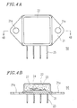
- FIG. 4A is a top view of an acceleration sensor 50
- Figure 4B is a cross sectional view of the acceleration sensor 50 along lines 4B-4B in Figure 4A .
- the acceleration sensor 50 includes a base 21 , a circuit board 23 bonded on a surface of the base 21 , a detection section 24 bonded on a surface of the circuit board 23 for detecting an acceleration to be sensed, and a cover 22 fixed to the base 21 by welding or the like for creating a sealed inner space 27 in which the circuit board 23 and the detection section 24 are located.
- the cover 22 prevents foreign substances from entering the inner space 27 .
- the detection section 24 on the circuit board 23 is connected to terminals 25 fixed to the base 21 in the state of being electrically insulated from the base 21 , and is connected to an external circuit via the terminals 25 .
- the base 21 has holes 21a in the vicinity of two ends thereof for attaching the acceleration sensor 50 to a prescribed position of an object for which an acceleration is to be sensed, for example, an automobile.
- the acceleration sensor 50 is used in the state of being connected to an electric circuit for controlling the operation of, for example, an air bag system of an automobile.
- the acceleration sensor 50 is attached to a prescribed position of an automobile by inserting screws through the holes 21a , and the terminals 25 are electrically connected to a circuit board (not shown) on which the electric circuit for controlling the operation of the air bag system is located.
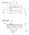
- Figure 5A is a top view of the detection section 24
- Figure 5B is a cross sectional view of the detection section 24 along lines 5B-5B in Figure 5A .
- the detection section 24 includes a fixed portion 24b and a movable cantilever beam 24a extended from the fixed portion 24b .
- the detection section 24 includes a space 24e below the cantilever beam 24a for allowing the cantilever beam 24a to move.
- the cantilever beam 24a includes a base portion 24c and a weight portion 24d extending out from the base portion 24c .
- the weight portion 24d is thicker than the base portion 24c .
- a strain detector 26 is located on the base portion 24c of the cantilever beam 24a .
- the conventional acceleration sensor 50 operates in the following manner.
- the acceleration sensor 50 is attached to, for example, an automobile by screws or the like. Movement of the automobile is transmitted to the base 21 . Then, the movement is transmitted to the fixed portion 24b via the circuit board 23 , and further to the cantilever beam 24a . Thus, the cantilever beam 24a is moved by the force of inertia of the weight portion 24d . By such movement of the cantilever beam 24a , the base portion 24c is bent in proportion to the acceleration caused by the movement. By appropriately setting the thickness of the base portion 24c and the weight portion 24d , the amount of bending is detected as a change in the resistance of the strain detector 26 . A signal indicating the amount of bending detected by the strain detector 26 is amplified by an amplifier (not shown) provided on the circuit board 23 and is output from the terminals 25 to the circuit board in the automobile as a signal indicating the amount of detected acceleration.
- the amplifier and the detection section 24 are provided on the circuit board 23 .
- the entire structure of the acceleration sensor 50 is enlarged, which enlarges the air bag system provided with the acceleration sensor 50 .
- the conventional acceleration sensor 50 is attached to the object for which an acceleration is to be sensed by inserting screws through the holes 21a , the liberty in attachment is restricted and the attachment process is complicated.
- An acceleration sensor includes a case having a bottom part, a pair of opposed walls substantially perpendicular to the bottom part, and a pair of first projections located on the bottom part; a detection section attached to the case via the pair of first projections for detecting an acceleration and outputting a signal indicating the acceleration; a spacer located on the bottom part of the case; an amplifier circuit board attached to the case in the state of being opposed to the detection section with the spacer interposed therebetween and having an amplifier on a substrate thereof for amplifying the signal output by the detection section; relay terminals for electrically connecting the detection section and the amplifier circuit board; and output terminals electrically connected to the amplifier circuit board for supplying the amplified signal to an external circuit.
- the amplifier circuit board has a pair of lands, the pair of walls of the case each have a tongue in contact with the lands respectively in the state of being bent, and each of the lands and the respective tongue are bonded to each other by soldering.
- the spacer has a frame surrounding the detection section.
- the spacer has a plurality of bosses on a bottom surface thereof integral with the spacer for preventing electric contact between the output terminals and the case.
- areas where the case, the spacer, and the amplifier circuit board are in contact with one another are coated with a coating agent to seal an inner space which is defined by the case, the spacer and the amplifier circuit board and includes the detection section.
- the amplifier circuit board has a circuit adjustment section on a top surface of the substrate thereof for adjusting an amplification factor of the amplifier.
- the bottom part of the case has a pair of second projections in the vicinity of two corners thereof used for attaching the acceleration sensor to an object for which an acceleration is to be sensed.
- the pair of walls of the case each have a third projection and a cutout formed at the foot of the third projection.
- the third projection is bent so that the concave surface thereof faces inward.
- the pair of first projections of the case have first holes respectively
- the detection section has a pair of second holes aligned with the first holes, and the detection section is attached to the first projections of the case in the state of being elevated from the bottom part of the case.
- the detection section is attached to the case by caulking a rivet inserted through the first holes and the second holes.
- the invention described herein makes possible the advantage of providing a small acceleration sensor which can be attached more easily with sufficient liberty.
- FIG. 1 is an exploded isometric view of the acceleration sensor 100 .
- Figure 2A is a top view of the acceleration sensor 100
- Figure 2B is a cross sectional view thereof along lines 2B-2B in Figure 2A .
- the acceleration sensor 100 includes a case 1 , a detection section 4 , an insulation spacer 8 , and an amplifier circuit board 3 .
- the case 1 has a bottom part 2 and two walls 6 which are substantially perpendicular to the bottom part 2 and opposed to each other.
- the case 1 is formed to have such a shape by treating a metal plate having a thickness of 0.2 mm to 1.0 mm, for example, 0.4 mm by sheet metal working.
- a metal plate having a thickness of 0.2 mm to 1.0 mm, for example, 0.4 mm by sheet metal working.
- tin-plated steel, solder-plated steel, cold-rolled steel or the like may be used.
- the case 1 has a pair of projections 1a (only one of them is shown in Figure 1 ) formed by drawing, and each projection 1a has a hole 1b at the center thereof.
- the bottom part 2 has a pair of projections 1j .
- Each projection 1j is respectively located in the vicinity of one of the two walls and extended from one of two ends of an edge 1f from which no wall is formed.
- the projections 1j are used to position the acceleration sensor 100 with respect to an object for which an acceleration is to be sensed (hereinafter, referred to simply as "object") such as an automobile (not shown).
- object an object for which an acceleration is to be sensed
- the bottom part 2 further has a plurality of holes 1c along the edge 1f for allowing output terminals 5 to be inserted therethrough.
- Each wall 6 has a pair of tongues 1d used for attaching an amplifier circuit board 3 to the case 1 .
- Each wall further has a substantially ' ⁇ '-shaped projection 1e used for attaching the acceleration sensor 100 to the object.
- Each projection 1e extends substantially parallel to the bottom part 2 from a top corner of the wall 6 on the same side as the edge 1f , and is bent so as to have a substantially ' ⁇ '-shape with the concave surface thereof facing inward.
- Each wall 6 further has a cutout 1g at the foot of the projection 1e .
- the acceleration sensor 100 can be attached to the object easily.
- the projections 1e which have the above-described shape, are distorted elastically when the acceleration sensor 100 is attached to the object, thus to allow for easy and secure attachment.
- the cutouts 1g at the foot of the projections 1e are formed to enhance elasticity of the projections 1e when the projections 1e are inserted into the object.
- the cutouts 1g also absorb the stress generated by the elastic distortion of the projections 1e by the insertion and thus prevent transmission of the stress to the detection section 4 .
- the detection section 4 includes a metal core plate 4b , which has a pair of holes 4a at corresponding positions to the holes 1b in the projections 1a .
- the detection section 4 is attached to the case 1 using the holes 4a and the holes 1b as is described below in detail.
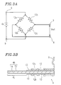
- the detection section 4 has a bridge circuit ( Figure 3A ) including a pair of strain resistors 12a and a pair of strain resistors 12b (only 12a are shown in Figure 1 ) and a plurality of relay terminals 9 connected to the strain resistors 12a and 12b . A free end of each relay terminal 9 is projected upward.
- Figure 3B is a cross sectional view of the detection section 4 along lines 3B-3B in Figure 1 .
- the metal core plate 4b which includes a base plate 14 formed of stainless steel or the like and a vitreous enamel layer 15 wrapping the base plate 14 .
- the strain resistors 12a and 12b are provided on top and bottom surfaces of the vitreous enamel layer 15 , respectively.
- the strain resistors 12a and 12b are each connected to an electrode 13 provided on the vitreous enamel layer 15 .
- the electrodes 13 are typically formed of a Ag-based thick film material, but may be formed of a Au-based thick film material or the like.
- the electrodes 13 are each connected to the relay terminal 9 located on the metal core plate 4b along the same side as the edge 1f .
- the relay terminals 9 are used to transmit an output signal from the detection section 4 to the amplifier circuit board 3 .
- the strain resistors 12a and 12b , the electrodes 13 , and the relay terminals 9 are connected to form the bridge circuit shown in Figure 3A . Between two of the relay terminals 9 corresponding to input terminals of the bridge circuit, an external power supply Vs is provided. From the bridge circuit, a voltage Vout indicating the acceleration detected by the acceleration sensor 100 is output across two of the relay terminals 9 corresponding to output terminals of the bridge circuit.
- an insulation spacer 8 has a frame 8c surrounding the detection section 4 which is rectangular.
- the insulation spacer 8 is typically formed of PBT (polybutyleneterephthalate), but may be formed of PPS (polyphenylenesulfide), polyamide, or the like.
- a plurality of output terminals 5 are attached to the insulation spacer 8 by insert molding or press fitting. Each output terminal 5 is projected upward and downward from the frame 8c .
- the output terminals 5 are connected to the amplifier circuit board 3 and are used for supplying a final output signal from the acceleration sensor 100 to an external circuit.
- each output terminal 5 immediately below the frame 8c is covered by a boss 8b which is integrally formed with the frame 8c .
- a part of each output terminal 5 extending downward from the boss 8b is inserted into the respective hole 1c while being prevented from electrically contacting the case 1 by the boss 8b . Due to the boss 8b , electrical contact of the output terminals 5 to the case 1 is prevented even if the output terminals 5 are bent during transportation. Thus, defective operation of the acceleration sensor 100 can be avoided.
- the insulation spacer 8 has a pair of projections 8a on top surfaces of opposed sides of the frame 8c .
- the projections 8a are used for attaching the amplifier circuit board 3 to the insulation spacer 8 as is described below.
- the amplifier circuit board 3 is located opposed to the detection section 4 with the insulation spacer 8 being interposed therebetween.
- the amplifier circuit board 3 has circuit adjusting resistors 10 as well as capacitors, resistors and the like on a top surface of a substrate 3c . Such components form an amplifier.
- the substrate 3c has a pair of recesses 3a on a peripheral surface thereof at corresponding positions to the projections 8a .
- the substrate 3c also has a plurality of holes 3b along the same side as the edge 1f .
- the recesses 3a and the holes 3b are used for attaching the amplifier circuit board 3 to the insulation spacer 8 as is described below.
- the above-described parts of the acceleration sensor 100 are assembled in the following manner.
- the detection section 4 is attached to the case 1 by aligning the holes 4a to the holes 1b and caulking rivets 7 inserted into the holes 4a and 1b .
- the detection section 4 is elevated from the bottom part 2 of the case 1 by the height of the projections 1a .
- caulking By use of caulking, the number of steps for attaching the detection section 4 to the case 1 is reduced.
- the insulation spacer 8 is attached to the case 1 while inserting the output terminals 5 of the insulation spacer 8 into the holes 1c of the case 1 .
- the amplifier circuit board 3 is then attached to the insulation spacer 8 in the following manner.
- the amplifier circuit board 3 is positioned with respect to the insulation spacer 8 by respectively inserting the output terminals 5 extended from the insulation spacer 8 and the relay terminals 9 extended from the detection section 4 into the holes 3b and also by fitting the projections 8a with the recesses 3a .
- the amplifier circuit board 3 can be secured by the insulation spacer 8 with pressure.
- the tongues 1d in the walls 6 are folded inward to hold the amplifier circuit board 3 . Then, the output terminals 5 and the relay terminals 9 are soldered by heating with light radiation or the like to be electrically connected to the amplifier circuit board 3 .
- the detection section 4 the insulation spacer 8 , and the amplifier circuit board 3 are attached to the case 1 .
- the circuit adjusting resistors 10 are treated by laser trimming or the like to have a prescribed resistance. Thus, the amplification factor of the amplifier with respect to the acceleration signal output by the detection section 4 is adjusted to be a prescribed value.
- the acceleration sensor 100 is completed in this manner.
- a rectangular part 4c of the metal core plate 4b which does not have the relay terminals 9 is flexible and can be moved sufficiently in an inner space defined by the case 1 , the insulation spacer 8 , and the amplifier circuit board 3 .
- the tongues 1d of the case 1 hold lands 3c ( Figure 2A ) of the amplifier circuit board 3 , respectively. By soldering the lands 3c and the tongues 1d , more secure attachment of the amplifier circuit board 3 to the case 1 is guaranteed, thus to increase the mechanical strength of the acceleration sensor 100 .
- the acceleration sensor 100 operates in the following manner.
- the acceleration sensor 100 is attached to, for example, a circuit board for controlling the operation of an air bag system of an automobile (not shown) by insertion of the projections 1e and 1j and the output terminals 5 and soldering. In such a state, the movement of the object is transmitted to the detection section 4 .
- the strain resistors 12a and 12b and the vicinity thereof are bent by the force of inertia of the rectangular part 4c .
- the resistance of the strain resistor 12a on the top surface of the metal core plate 4b and the resistance of the strain resistor 12b on the bottom surface of the metal core plate 4b change in different polarities.
- the resistance of the bridge circuit is changed, and such a change is output as a voltage Vout from the bridge circuit shown in Figure 3A and sent to the amplifier circuit board 3 via the relay terminals 9 .
- the amplifier (not shown) on the amplifier circuit board 3 adjusted to have a prescribed amplification factor by the circuit adjusting resistor 10 amplifies the output Vout from the bridge circuit.
- the amplified signal is sent to the control board of the object via the output terminals 5 as a signal indicating the acceleration of the object.
- the acceleration sensor 100 has a circuit adjustment section including the circuit adjusting resistor 10 for adjustment, on a top, namely, outer surface of the substrate 3c of the amplifier circuit board 3 . Due to such a structure, the operation characteristics of the acceleration sensor 100 can be easily adjusted after the assembly of parts into the acceleration sensor 100 . Accordingly, the number of steps for adjustment is reduced and the detection precision is improved.
- the detection section 4 is surrounded by the case 1 , the insulation spacer 8 , and the amplifier circuit board 3 , and further is opposed to the amplifier circuit board 3 . Due to such a structure, invasion of foreign substances to the detection section 4 is prohibited, and the size of the acceleration sensor 100 is reduced. Especially the insulation spacer 8 surrounding the detection section 4 protects the detection section 4 from dust and the like, thus improving the detection quality.
- the projections 1e facilitate attachment and electric connection of the acceleration sensor 100 to, for example, the circuit board of an air bag system of an automobile.
- the inner space including the detection section 4 is sealed more reliably.
- a coating agent By treating the surface of the acceleration sensor 100 or at least contact areas of the case 1 , the insulation spacer 8 , and the amplifier circuit board 3 with dipping, spraying or the like with a coating agent, the inner space including the detection section 4 is sealed more reliably.
- Such coating is effective for preventing invasion of foreign substances into the inner space and thus for improving the reliability of the acceleration sensor 100 .
- the detection section 4 and the case 1 may be attached to each other using screws or pins, or welding to provide the same effects.
- One of such methods and caulking may be combined, in which case, the detection section 4 is attached to the case 1 with certain excessiveness and thus more reliably.
Abstract
Description
- The present invention relates to an acceleration sensor used in, for example, an air bag system of an automobile for detecting an acceleration caused by, for example, impact.
- A
conventional acceleration sensor 50 will be described with reference to Figures 4A, 4B, 5A and 5B. Figure 4A is a top view of anacceleration sensor 50, and Figure 4B is a cross sectional view of theacceleration sensor 50 alonglines 4B-4B in Figure 4A. - The
acceleration sensor 50 includes abase 21, acircuit board 23 bonded on a surface of thebase 21, adetection section 24 bonded on a surface of thecircuit board 23 for detecting an acceleration to be sensed, and acover 22 fixed to thebase 21 by welding or the like for creating a sealedinner space 27 in which thecircuit board 23 and thedetection section 24 are located. Thecover 22 prevents foreign substances from entering theinner space 27. Thedetection section 24 on thecircuit board 23 is connected toterminals 25 fixed to thebase 21 in the state of being electrically insulated from thebase 21, and is connected to an external circuit via theterminals 25. Thebase 21 hasholes 21a in the vicinity of two ends thereof for attaching theacceleration sensor 50 to a prescribed position of an object for which an acceleration is to be sensed, for example, an automobile. - The
acceleration sensor 50 is used in the state of being connected to an electric circuit for controlling the operation of, for example, an air bag system of an automobile. Theacceleration sensor 50 is attached to a prescribed position of an automobile by inserting screws through theholes 21a, and theterminals 25 are electrically connected to a circuit board (not shown) on which the electric circuit for controlling the operation of the air bag system is located. - Figure 5A is a top view of the
detection section 24, and Figure 5B is a cross sectional view of thedetection section 24 alonglines 5B-5B in Figure 5A. - The
detection section 24 includes afixed portion 24b and amovable cantilever beam 24a extended from the fixedportion 24b. Thedetection section 24 includes aspace 24e below thecantilever beam 24a for allowing thecantilever beam 24a to move. Thecantilever beam 24a includes abase portion 24c and aweight portion 24d extending out from thebase portion 24c. Theweight portion 24d is thicker than thebase portion 24c. Astrain detector 26 is located on thebase portion 24c of thecantilever beam 24a. - The
conventional acceleration sensor 50 operates in the following manner. - The
acceleration sensor 50 is attached to, for example, an automobile by screws or the like. Movement of the automobile is transmitted to thebase 21. Then, the movement is transmitted to thefixed portion 24b via thecircuit board 23, and further to thecantilever beam 24a. Thus, thecantilever beam 24a is moved by the force of inertia of theweight portion 24d. By such movement of thecantilever beam 24a, thebase portion 24c is bent in proportion to the acceleration caused by the movement. By appropriately setting the thickness of thebase portion 24c and theweight portion 24d, the amount of bending is detected as a change in the resistance of thestrain detector 26. A signal indicating the amount of bending detected by thestrain detector 26 is amplified by an amplifier (not shown) provided on thecircuit board 23 and is output from theterminals 25 to the circuit board in the automobile as a signal indicating the amount of detected acceleration. - In the
conventional acceleration sensor 50, the amplifier and thedetection section 24 are provided on thecircuit board 23. Thus, the entire structure of theacceleration sensor 50 is enlarged, which enlarges the air bag system provided with theacceleration sensor 50. Moreover, since theconventional acceleration sensor 50 is attached to the object for which an acceleration is to be sensed by inserting screws through theholes 21a, the liberty in attachment is restricted and the attachment process is complicated. - An acceleration sensor according to the present invention includes a case having a bottom part, a pair of opposed walls substantially perpendicular to the bottom part, and a pair of first projections located on the bottom part; a detection section attached to the case via the pair of first projections for detecting an acceleration and outputting a signal indicating the acceleration; a spacer located on the bottom part of the case; an amplifier circuit board attached to the case in the state of being opposed to the detection section with the spacer interposed therebetween and having an amplifier on a substrate thereof for amplifying the signal output by the detection section; relay terminals for electrically connecting the detection section and the amplifier circuit board; and output terminals electrically connected to the amplifier circuit board for supplying the amplified signal to an external circuit.
- In one aspect of the present invention, the amplifier circuit board has a pair of lands, the pair of walls of the case each have a tongue in contact with the lands respectively in the state of being bent, and each of the lands and the respective tongue are bonded to each other by soldering.
- In one aspect of the present invention, the spacer has a frame surrounding the detection section.
- In one aspect of the present invention, the spacer has a plurality of bosses on a bottom surface thereof integral with the spacer for preventing electric contact between the output terminals and the case.
- In one aspect of the present invention, areas where the case, the spacer, and the amplifier circuit board are in contact with one another are coated with a coating agent to seal an inner space which is defined by the case, the spacer and the amplifier circuit board and includes the detection section.
- In one aspect of the present invention, the amplifier circuit board has a circuit adjustment section on a top surface of the substrate thereof for adjusting an amplification factor of the amplifier.
- In one aspect of the present invention, the bottom part of the case has a pair of second projections in the vicinity of two corners thereof used for attaching the acceleration sensor to an object for which an acceleration is to be sensed.
- In one aspect of the present invention, the pair of walls of the case each have a third projection and a cutout formed at the foot of the third projection. The third projection is bent so that the concave surface thereof faces inward.
- In one aspect of the present invention, the pair of first projections of the case have first holes respectively, the detection section has a pair of second holes aligned with the first holes, and the detection section is attached to the first projections of the case in the state of being elevated from the bottom part of the case.
- In one aspect of the present invention, the detection section is attached to the case by caulking a rivet inserted through the first holes and the second holes.
- Thus, the invention described herein makes possible the advantage of providing a small acceleration sensor which can be attached more easily with sufficient liberty.
- This and other advantages of the present invention will become apparent to those skilled in the art upon reading and understanding the following detailed description with reference to the accompanying figures.
-
- Figure 1 is an exploded isometric view of an acceleration sensor in an example according to the present invention;
- Figure 2A is a top view of the acceleration sensor shown in Figure 1, and Figure 2B is a cross sectional view thereof along
lines 2B-2B in Figure 2A; - Figure 3A is a circuit diagram of an equivalent circuit of a bridge circuit included in a detection section of the acceleration sensor shown in Figure 1;
- Figure 3B is a cross sectional view of the detection section along
lines 3B-3B in Figure 1; - Figure 4A is a top view of a conventional acceleration sensor, and Figure 4B is a cross sectional view thereof along
lines 4B-4B in Figure 4A; and - Figure 5A is a top view of a detection section included in the conventional acceleration sensor, and Figure 5B is a cross sectional view thereof along
lines 5B-5B in Figure 5A. - Hereinafter, the present invention will be described by way of illustrative examples with reference to the accompanying drawings.
- An
acceleration sensor 100 in an example according to the present invention will be described with reference to Figures 1, 2A, 2B, 3A and 3B. Figure 1 is an exploded isometric view of theacceleration sensor 100. Figure 2A is a top view of theacceleration sensor 100, and Figure 2B is a cross sectional view thereof alonglines 2B-2B in Figure 2A. - The
acceleration sensor 100 includes a case 1, adetection section 4, an insulation spacer 8, and anamplifier circuit board 3. - The case 1 has a
bottom part 2 and twowalls 6 which are substantially perpendicular to thebottom part 2 and opposed to each other. The case 1 is formed to have such a shape by treating a metal plate having a thickness of 0.2 mm to 1.0 mm, for example, 0.4 mm by sheet metal working. As the material for the metal plate, tin-plated steel, solder-plated steel, cold-rolled steel or the like may be used. - The case 1 has a pair of projections 1a (only one of them is shown in Figure 1) formed by drawing, and each projection 1a has a
hole 1b at the center thereof. Thebottom part 2 has a pair ofprojections 1j. Eachprojection 1j is respectively located in the vicinity of one of the two walls and extended from one of two ends of anedge 1f from which no wall is formed. Theprojections 1j are used to position theacceleration sensor 100 with respect to an object for which an acceleration is to be sensed (hereinafter, referred to simply as "object") such as an automobile (not shown). Thebottom part 2 further has a plurality ofholes 1c along theedge 1f for allowingoutput terminals 5 to be inserted therethrough. - Each
wall 6 has a pair oftongues 1d used for attaching anamplifier circuit board 3 to the case 1. Each wall further has a substantially '<'-shapedprojection 1e used for attaching theacceleration sensor 100 to the object. Eachprojection 1e extends substantially parallel to thebottom part 2 from a top corner of thewall 6 on the same side as theedge 1f, and is bent so as to have a substantially '<'-shape with the concave surface thereof facing inward. Eachwall 6 further has acutout 1g at the foot of theprojection 1e. - Due to the
projections 1j and theprojections 1e, theacceleration sensor 100 can be attached to the object easily. Especially theprojections 1e, which have the above-described shape, are distorted elastically when theacceleration sensor 100 is attached to the object, thus to allow for easy and secure attachment. - The
cutouts 1g at the foot of theprojections 1e are formed to enhance elasticity of theprojections 1e when theprojections 1e are inserted into the object. Thecutouts 1g also absorb the stress generated by the elastic distortion of theprojections 1e by the insertion and thus prevent transmission of the stress to thedetection section 4. - The
detection section 4 includes ametal core plate 4b, which has a pair of holes 4a at corresponding positions to theholes 1b in the projections 1a. Thedetection section 4 is attached to the case 1 using the holes 4a and theholes 1b as is described below in detail. Thedetection section 4 has a bridge circuit (Figure 3A) including a pair ofstrain resistors 12a and a pair ofstrain resistors 12b (only 12a are shown in Figure 1) and a plurality ofrelay terminals 9 connected to thestrain resistors relay terminal 9 is projected upward. - Figure 3B is a cross sectional view of the
detection section 4 alonglines 3B-3B in Figure 1. Themetal core plate 4b, which includes abase plate 14 formed of stainless steel or the like and avitreous enamel layer 15 wrapping thebase plate 14. Thestrain resistors vitreous enamel layer 15, respectively. Thestrain resistors electrode 13 provided on thevitreous enamel layer 15. Theelectrodes 13 are typically formed of a Ag-based thick film material, but may be formed of a Au-based thick film material or the like. - The
electrodes 13 are each connected to therelay terminal 9 located on themetal core plate 4b along the same side as theedge 1f. Therelay terminals 9 are used to transmit an output signal from thedetection section 4 to theamplifier circuit board 3. - The
strain resistors electrodes 13, and therelay terminals 9 are connected to form the bridge circuit shown in Figure 3A. Between two of therelay terminals 9 corresponding to input terminals of the bridge circuit, an external power supply Vs is provided. From the bridge circuit, a voltage Vout indicating the acceleration detected by theacceleration sensor 100 is output across two of therelay terminals 9 corresponding to output terminals of the bridge circuit. - Returning to Figure 1, an insulation spacer 8 has a
frame 8c surrounding thedetection section 4 which is rectangular. The insulation spacer 8 is typically formed of PBT (polybutyleneterephthalate), but may be formed of PPS (polyphenylenesulfide), polyamide, or the like. - A plurality of
output terminals 5 are attached to the insulation spacer 8 by insert molding or press fitting. Eachoutput terminal 5 is projected upward and downward from theframe 8c. Theoutput terminals 5 are connected to theamplifier circuit board 3 and are used for supplying a final output signal from theacceleration sensor 100 to an external circuit. - A part of each
output terminal 5 immediately below theframe 8c is covered by aboss 8b which is integrally formed with theframe 8c. A part of eachoutput terminal 5 extending downward from theboss 8b is inserted into therespective hole 1c while being prevented from electrically contacting the case 1 by theboss 8b. Due to theboss 8b, electrical contact of theoutput terminals 5 to the case 1 is prevented even if theoutput terminals 5 are bent during transportation. Thus, defective operation of theacceleration sensor 100 can be avoided. - The insulation spacer 8 has a pair of
projections 8a on top surfaces of opposed sides of theframe 8c. Theprojections 8a are used for attaching theamplifier circuit board 3 to the insulation spacer 8 as is described below. - The
amplifier circuit board 3 is located opposed to thedetection section 4 with the insulation spacer 8 being interposed therebetween. Theamplifier circuit board 3 hascircuit adjusting resistors 10 as well as capacitors, resistors and the like on a top surface of asubstrate 3c. Such components form an amplifier. Thesubstrate 3c has a pair of recesses 3a on a peripheral surface thereof at corresponding positions to theprojections 8a. Thesubstrate 3c also has a plurality ofholes 3b along the same side as theedge 1f. The recesses 3a and theholes 3b are used for attaching theamplifier circuit board 3 to the insulation spacer 8 as is described below. - The above-described parts of the
acceleration sensor 100 are assembled in the following manner. - The
detection section 4 is attached to the case 1 by aligning the holes 4a to theholes 1b andcaulking rivets 7 inserted into theholes 4a and 1b. Thus, thedetection section 4 is elevated from thebottom part 2 of the case 1 by the height of the projections 1a. By use of caulking, the number of steps for attaching thedetection section 4 to the case 1 is reduced. - After the
detection section 4 is attached to the case 1, the insulation spacer 8 is attached to the case 1 while inserting theoutput terminals 5 of the insulation spacer 8 into theholes 1c of the case 1. - The
amplifier circuit board 3 is then attached to the insulation spacer 8 in the following manner. - The
amplifier circuit board 3 is positioned with respect to the insulation spacer 8 by respectively inserting theoutput terminals 5 extended from the insulation spacer 8 and therelay terminals 9 extended from thedetection section 4 into theholes 3b and also by fitting theprojections 8a with the recesses 3a. By setting the distance between theprojections 8a to be slightly shorter than the distance between the recesses 3a, theamplifier circuit board 3 can be secured by the insulation spacer 8 with pressure. - The
tongues 1d in thewalls 6 are folded inward to hold theamplifier circuit board 3. Then, theoutput terminals 5 and therelay terminals 9 are soldered by heating with light radiation or the like to be electrically connected to theamplifier circuit board 3. - In this manner, the
detection section 4, the insulation spacer 8, and theamplifier circuit board 3 are attached to the case 1. - The
circuit adjusting resistors 10 are treated by laser trimming or the like to have a prescribed resistance. Thus, the amplification factor of the amplifier with respect to the acceleration signal output by thedetection section 4 is adjusted to be a prescribed value. Theacceleration sensor 100 is completed in this manner. - In the
acceleration sensor 100 having such a structure, arectangular part 4c of themetal core plate 4b which does not have therelay terminals 9 is flexible and can be moved sufficiently in an inner space defined by the case 1, the insulation spacer 8, and theamplifier circuit board 3. - The
tongues 1d of the case 1 hold lands 3c (Figure 2A) of theamplifier circuit board 3, respectively. By soldering thelands 3c and thetongues 1d, more secure attachment of theamplifier circuit board 3 to the case 1 is guaranteed, thus to increase the mechanical strength of theacceleration sensor 100. - The
acceleration sensor 100 operates in the following manner. - First, the
acceleration sensor 100 is attached to, for example, a circuit board for controlling the operation of an air bag system of an automobile (not shown) by insertion of theprojections output terminals 5 and soldering. In such a state, the movement of the object is transmitted to thedetection section 4. - When the object moves, the
strain resistors rectangular part 4c. Thus, the resistance of thestrain resistor 12a on the top surface of themetal core plate 4b and the resistance of thestrain resistor 12b on the bottom surface of themetal core plate 4b change in different polarities. As a result, the resistance of the bridge circuit is changed, and such a change is output as a voltage Vout from the bridge circuit shown in Figure 3A and sent to theamplifier circuit board 3 via therelay terminals 9. The amplifier (not shown) on theamplifier circuit board 3 adjusted to have a prescribed amplification factor by thecircuit adjusting resistor 10 amplifies the output Vout from the bridge circuit. The amplified signal is sent to the control board of the object via theoutput terminals 5 as a signal indicating the acceleration of the object. - The
acceleration sensor 100 according to the present invention has a circuit adjustment section including thecircuit adjusting resistor 10 for adjustment, on a top, namely, outer surface of thesubstrate 3c of theamplifier circuit board 3. Due to such a structure, the operation characteristics of theacceleration sensor 100 can be easily adjusted after the assembly of parts into theacceleration sensor 100. Accordingly, the number of steps for adjustment is reduced and the detection precision is improved. - The
detection section 4 is surrounded by the case 1, the insulation spacer 8, and theamplifier circuit board 3, and further is opposed to theamplifier circuit board 3. Due to such a structure, invasion of foreign substances to thedetection section 4 is prohibited, and the size of theacceleration sensor 100 is reduced. Especially the insulation spacer 8 surrounding thedetection section 4 protects thedetection section 4 from dust and the like, thus improving the detection quality. - The
projections 1e facilitate attachment and electric connection of theacceleration sensor 100 to, for example, the circuit board of an air bag system of an automobile. - By treating the surface of the
acceleration sensor 100 or at least contact areas of the case 1, the insulation spacer 8, and theamplifier circuit board 3 with dipping, spraying or the like with a coating agent, the inner space including thedetection section 4 is sealed more reliably. Such coating is effective for preventing invasion of foreign substances into the inner space and thus for improving the reliability of theacceleration sensor 100. - The
detection section 4 and the case 1 may be attached to each other using screws or pins, or welding to provide the same effects. One of such methods and caulking may be combined, in which case, thedetection section 4 is attached to the case 1 with certain excessiveness and thus more reliably. - Various other modifications will be apparent to and can be readily made by those skilled in the art without departing from the scope and spirit of this invention. Accordingly, it is not intended that the scope of the claims appended hereto be limited to the description as set forth herein, but rather that the claims be broadly construed.
Claims (10)
- An acceleration sensor, comprising:
a case having a bottom part, a pair of opposed walls substantially perpendicular to the bottom part, and a pair of first projections located on the bottom part;
a detection section attached to the case via the pair of first projections for detecting an acceleration and outputting a signal indicating the acceleration;
a spacer located on the bottom part of the case;
an amplifier circuit board attached to the case in the state of being opposed to the detection section with the spacer interposed therebetween and having an amplifier on a substrate thereof for amplifying the signal output by the detection section;
relay terminals for electrically connecting the detection section and the amplifier circuit board; and
output terminals electrically connected to the amplifier circuit board for supplying the amplified signal to an external circuit. - An acceleration sensor according to claim 1, wherein the amplifier circuit board has a pair of lands, the pair of walls of the case each have a tongue in contact with the lands respectively in the state of being bent, and each of the lands and the respective tongue are bonded to each other by soldering.
- An acceleration sensor according to claim 1, wherein the spacer has a frame surrounding the detection section.
- An acceleration sensor according to claim 1, wherein the spacer has a plurality of bosses provided on a bottom surface thereof integrally with the spacer for preventing electric contact between the output terminals and the case.
- An acceleration sensor according to claim 1, wherein areas where the case, the spacer, and the amplifier circuit board are in contact with one another are coated with a coating agent to seal an inner space which is defined by the case, the spacer and the amplifier circuit board and include the detection section.
- An acceleration sensor according to claim 1, wherein the amplifier circuit board has a circuit adjustment section on a top surface of the substrate thereof for adjusting an amplification factor of the amplifier.
- An acceleration sensor according to claim 1, wherein the bottom part of the case has a pair of second projections in the vicinity of two corners thereof used for attaching the acceleration sensor to an object for which an acceleration is to be sensed.
- An acceleration sensor according to claim 1, wherein the pair of walls of the case each have a third projection and a cutout formed at the foot of the third projection, the third projection being bent so that the concave surface thereof faces inward.
- An acceleration sensor according to claim 1, wherein the pair of first projections of the case have first holes respectively, the detection section has a pair of second holes aligned with the first holes, and the detection section is attached to the first projections of the case in the state of being elevated from the bottom part of the case.
- An acceleration sensor according to claim 9, wherein the detection section is attached to the case by caulking a rivet inserted through the first holes and the second holes.
Applications Claiming Priority (3)
| Application Number | Priority Date | Filing Date | Title |
|---|---|---|---|
| JP6223353A JPH0886800A (en) | 1994-09-19 | 1994-09-19 | Acceleration sensor |
| JP22335394 | 1994-09-19 | ||
| JP223353/94 | 1994-09-19 |
Publications (3)
| Publication Number | Publication Date |
|---|---|
| EP0704701A2 true EP0704701A2 (en) | 1996-04-03 |
| EP0704701A3 EP0704701A3 (en) | 1997-04-09 |
| EP0704701B1 EP0704701B1 (en) | 2000-01-12 |
Family
ID=16796834
Family Applications (1)
| Application Number | Title | Priority Date | Filing Date |
|---|---|---|---|
| EP95114644A Expired - Lifetime EP0704701B1 (en) | 1994-09-19 | 1995-09-18 | Acceleration sensor |
Country Status (4)
| Country | Link |
|---|---|
| US (1) | US5650567A (en) |
| EP (1) | EP0704701B1 (en) |
| JP (1) | JPH0886800A (en) |
| DE (1) | DE69514464T2 (en) |
Cited By (2)
| Publication number | Priority date | Publication date | Assignee | Title |
|---|---|---|---|---|
| DE19717348A1 (en) * | 1997-04-24 | 1998-10-29 | Siemens Ag | Method of manufacturing a sensor assembly and sensor assembly |
| EP2947422A1 (en) * | 2001-11-29 | 2015-11-25 | Panasonic Intellectual Property Management Co., Ltd. | Angular velocity sensor |
Families Citing this family (9)
| Publication number | Priority date | Publication date | Assignee | Title |
|---|---|---|---|---|
| EP0852337A1 (en) | 1996-12-24 | 1998-07-08 | STMicroelectronics S.r.l. | A hermetically sealed semiconductor inertial sensor |
| EP0886144B1 (en) * | 1997-06-19 | 2006-09-06 | STMicroelectronics S.r.l. | A hermetically sealed sensor with a movable microstructure |
| US6145380A (en) * | 1997-12-18 | 2000-11-14 | Alliedsignal | Silicon micro-machined accelerometer using integrated electrical and mechanical packaging |
| US6913472B2 (en) * | 2002-06-28 | 2005-07-05 | Siemens Vdo Automotive Corporation | Method and apparatus for attaching a sensor assembly in a control unit |
| KR100867946B1 (en) * | 2007-08-30 | 2008-11-10 | 콘티넨탈 오토모티브 일렉트로닉스 주식회사 | Assembly structure of heater controller for vehicle |
| ITTO20120542A1 (en) | 2012-06-20 | 2013-12-21 | St Microelectronics Srl | MICROELETTROMECHANICAL DEVICE WITH SIGNAL INSERTION THROUGH A PROTECTIVE HOOD AND METHOD FOR CHECKING A MICROELECTROMECHANICAL DEVICE |
| JP2014228295A (en) * | 2013-05-20 | 2014-12-08 | 株式会社デンソー | Semiconductor pressure sensor device |
| US10150440B2 (en) * | 2016-05-19 | 2018-12-11 | Ford Global Technologies, Llc | Restraints control module attachment assembly |
| US10144360B2 (en) | 2016-05-19 | 2018-12-04 | Ford Global Technologies, Llc | Restraints control module attachment assembly |
Family Cites Families (7)
| Publication number | Priority date | Publication date | Assignee | Title |
|---|---|---|---|---|
| DE2655604C2 (en) * | 1976-12-08 | 1984-11-29 | Robert Bosch Gmbh, 7000 Stuttgart | Delay recorder for triggering occupant protection devices in motor vehicles |
| DE3328114A1 (en) * | 1983-08-04 | 1985-02-14 | Robert Bosch Gmbh, 7000 Stuttgart | RELEASE DEVICE FOR RESTRAINT SYSTEMS IN MOTOR VEHICLES |
| US5003824A (en) * | 1989-12-26 | 1991-04-02 | Matsushita Electric Industrial Co., Ltd. | Vibration/acceleration sensor |
| US5233871A (en) * | 1991-11-01 | 1993-08-10 | Delco Electronics Corporation | Hybrid accelerometer assembly |
| US5345823A (en) * | 1991-11-12 | 1994-09-13 | Texas Instruments Incorporated | Accelerometer |
| DE9202533U1 (en) * | 1992-02-27 | 1992-04-23 | Mannesmann Kienzle Gmbh, 7730 Villingen-Schwenningen, De | |
| DE9309918U1 (en) * | 1993-07-03 | 1993-12-02 | Mannesmann Kienzle Gmbh | Accelerometer bracket |
-
1994
- 1994-09-19 JP JP6223353A patent/JPH0886800A/en active Pending
-
1995
- 1995-09-14 US US08/528,396 patent/US5650567A/en not_active Expired - Fee Related
- 1995-09-18 EP EP95114644A patent/EP0704701B1/en not_active Expired - Lifetime
- 1995-09-18 DE DE69514464T patent/DE69514464T2/en not_active Expired - Fee Related
Non-Patent Citations (1)
| Title |
|---|
| None |
Cited By (3)
| Publication number | Priority date | Publication date | Assignee | Title |
|---|---|---|---|---|
| DE19717348A1 (en) * | 1997-04-24 | 1998-10-29 | Siemens Ag | Method of manufacturing a sensor assembly and sensor assembly |
| US6098459A (en) * | 1997-04-24 | 2000-08-08 | Siemens Aktiengesellschaft | Method of producing a sensor subassembly, and sensor subassembly |
| EP2947422A1 (en) * | 2001-11-29 | 2015-11-25 | Panasonic Intellectual Property Management Co., Ltd. | Angular velocity sensor |
Also Published As
| Publication number | Publication date |
|---|---|
| EP0704701B1 (en) | 2000-01-12 |
| US5650567A (en) | 1997-07-22 |
| EP0704701A3 (en) | 1997-04-09 |
| DE69514464T2 (en) | 2000-06-21 |
| DE69514464D1 (en) | 2000-02-17 |
| JPH0886800A (en) | 1996-04-02 |
Similar Documents
| Publication | Publication Date | Title |
|---|---|---|
| EP0704701B1 (en) | Acceleration sensor | |
| US6757403B2 (en) | Electroacoustic transducers | |
| US5783750A (en) | Semiconductor sensor including laminated supporting pedestal | |
| KR100355136B1 (en) | Rotational speed sensor | |
| US4922374A (en) | Lightning protector assembly | |
| JPH11282360A (en) | Liquid crystal display device | |
| US20080245157A1 (en) | Distortion Detector | |
| US5535098A (en) | Electrical device, particularly switching and control device for motor vehicles | |
| EP1480003B1 (en) | Thickness detecting sensor | |
| JP3500294B2 (en) | Shield structure | |
| JP3404314B2 (en) | Pressure sensor | |
| JPH0541584Y2 (en) | ||
| JP4365982B2 (en) | Tilt sensor | |
| JP3063414B2 (en) | Electronics | |
| JP3801007B2 (en) | Weight sensor and manufacturing method thereof | |
| JP2540967Y2 (en) | Pressure sensor | |
| US4827234A (en) | Electromagnetic relay | |
| JPH09218123A (en) | Pressure sensor | |
| JPH0635443Y2 (en) | High frequency coil | |
| JP2598200Y2 (en) | Capacitive weight sensor | |
| JP2567103Y2 (en) | Ladder type filter | |
| CN116817997A (en) | Detection assembly and sensing device | |
| JP2004258005A (en) | Acceleration sensor | |
| JPH0735401Y2 (en) | Device for adding capacitors to DIP type IC elements | |
| JPH0629858Y2 (en) | Pushbutton switch with frame |
Legal Events
| Date | Code | Title | Description |
|---|---|---|---|
| PUAI | Public reference made under article 153(3) epc to a published international application that has entered the european phase |
Free format text: ORIGINAL CODE: 0009012 |
|
| 17P | Request for examination filed |
Effective date: 19950919 |
|
| AK | Designated contracting states |
Kind code of ref document: A2 Designated state(s): DE FR IT |
|
| K1C1 | Correction of patent application (title page) published |
Effective date: 19960403 |
|
| PUAL | Search report despatched |
Free format text: ORIGINAL CODE: 0009013 |
|
| AK | Designated contracting states |
Kind code of ref document: A3 Designated state(s): DE FR IT |
|
| 17Q | First examination report despatched |
Effective date: 19980514 |
|
| GRAG | Despatch of communication of intention to grant |
Free format text: ORIGINAL CODE: EPIDOS AGRA |
|
| GRAG | Despatch of communication of intention to grant |
Free format text: ORIGINAL CODE: EPIDOS AGRA |
|
| GRAH | Despatch of communication of intention to grant a patent |
Free format text: ORIGINAL CODE: EPIDOS IGRA |
|
| GRAH | Despatch of communication of intention to grant a patent |
Free format text: ORIGINAL CODE: EPIDOS IGRA |
|
| GRAA | (expected) grant |
Free format text: ORIGINAL CODE: 0009210 |
|
| AK | Designated contracting states |
Kind code of ref document: B1 Designated state(s): DE FR IT |
|
| REF | Corresponds to: |
Ref document number: 69514464 Country of ref document: DE Date of ref document: 20000217 |
|
| ET | Fr: translation filed | ||
| ITF | It: translation for a ep patent filed |
Owner name: STUDIO TORTA S.R.L. |
|
| PLBE | No opposition filed within time limit |
Free format text: ORIGINAL CODE: 0009261 |
|
| STAA | Information on the status of an ep patent application or granted ep patent |
Free format text: STATUS: NO OPPOSITION FILED WITHIN TIME LIMIT |
|
| 26N | No opposition filed | ||
| PGFP | Annual fee paid to national office [announced via postgrant information from national office to epo] |
Ref country code: FR Payment date: 20040908 Year of fee payment: 10 |
|
| PGFP | Annual fee paid to national office [announced via postgrant information from national office to epo] |
Ref country code: DE Payment date: 20040916 Year of fee payment: 10 |
|
| PG25 | Lapsed in a contracting state [announced via postgrant information from national office to epo] |
Ref country code: IT Free format text: LAPSE BECAUSE OF NON-PAYMENT OF DUE FEES;WARNING: LAPSES OF ITALIAN PATENTS WITH EFFECTIVE DATE BEFORE 2007 MAY HAVE OCCURRED AT ANY TIME BEFORE 2007. THE CORRECT EFFECTIVE DATE MAY BE DIFFERENT FROM THE ONE RECORDED. Effective date: 20050918 |
|
| PG25 | Lapsed in a contracting state [announced via postgrant information from national office to epo] |
Ref country code: DE Free format text: LAPSE BECAUSE OF NON-PAYMENT OF DUE FEES Effective date: 20060401 |
|
| PG25 | Lapsed in a contracting state [announced via postgrant information from national office to epo] |
Ref country code: FR Free format text: LAPSE BECAUSE OF NON-PAYMENT OF DUE FEES Effective date: 20060531 |
|
| REG | Reference to a national code |
Ref country code: FR Ref legal event code: ST Effective date: 20060531 |