US6098387A - Ground clearing apparatus - Google Patents
Ground clearing apparatus Download PDFInfo
- Publication number
- US6098387A US6098387A US09/247,094 US24709499A US6098387A US 6098387 A US6098387 A US 6098387A US 24709499 A US24709499 A US 24709499A US 6098387 A US6098387 A US 6098387A
- Authority
- US
- United States
- Prior art keywords
- drum
- blades
- shaft
- extending
- debris
- Prior art date
- Legal status (The legal status is an assumption and is not a legal conclusion. Google has not performed a legal analysis and makes no representation as to the accuracy of the status listed.)
- Expired - Fee Related
Links
Images


Classifications
-
- A—HUMAN NECESSITIES
- A01—AGRICULTURE; FORESTRY; ANIMAL HUSBANDRY; HUNTING; TRAPPING; FISHING
- A01G—HORTICULTURE; CULTIVATION OF VEGETABLES, FLOWERS, RICE, FRUIT, VINES, HOPS OR SEAWEED; FORESTRY; WATERING
- A01G20/00—Cultivation of turf, lawn or the like; Apparatus or methods therefor
- A01G20/40—Apparatus for cleaning the lawn or grass surface
- A01G20/43—Apparatus for cleaning the lawn or grass surface for sweeping, collecting or disintegrating lawn debris
- A01G20/47—Vacuum or blower devices
Definitions
- the invention is generally intended for use in the grooming of golf courses, particularly the greens thereof.
- the apparatus of the present invention involves an intermediate step. More particularly, as an initial step in grooming a green, an aerator is used to form multiple fertilizer-accommodating holes in the green, approximately 5/8 inches in diameter and four inches apart. The holes are formed by the removal of plugs of material. These plugs, along with any thatch which might have accumulated on the green, must be removed prior to the final grooming step.
- the present invention is directed to apparatus for clearing the green of the cut plugs, thatch, thatch balls, and the like with this material being effectively pulverized and redistributed back on the green surface in the form of a fine powder or dusting which not only prepares the surface for further grooming steps, but also retains and redistributes fertilizer and other nutrients which will have accumulated within pulverized materials.
- the apparatus or equipment of the invention utilizes a unique combination of flails and fan blades which create an air flow system which draws the plugs, leaves and thatch into the surrounding perforated drum wherein the material is effectively pulverized by the action of the flails and the fan blades.
- the blades are so positioned as to wipe against the interior surface of the drum to assist in the discharge of the material therethrough as a further pulverizing effect.
- This discharge of material is enhanced by the movement of the air with the blade and air movement also effectively continuously cleaning and clearing the drum perforations. This is particularly significant when moisture is present in the materials.
- the ground clearing assembly will preferably be mounted on a floating frame positioned within a larger mobile frame including a power source for driving the flail and fan unit, and means for attachment to an appropriate pulling vehicle such as a tractor.
- FIG. 1 is perspective view of the invention, including the ground clearing assembly and the mobile frame support;
- FIG. 2 is a side elevational view thereof with portions broken away for purposes of illustration;
- FIG. 3 is a perspective view, with portions broken away, of the ground clearing assembly
- FIG. 4 is an enlarged perspective view of the flail and fan unit
- FIG. 5 is an enlarged cross-sectional detail taken substantially on a plane passing along the line 5--5 in FIG. 3;
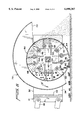
- FIG. 6 is an enlarged traverse cross-sectional view taken substantially on a plane passing along the line 6--6 in FIG. 3.
- the ground clearing apparatus of the invention includes a mobile frame 10 formed of welded bars 12, preferably hollow so as to minimize the weight of the apparatus.
- the rollers project only slightly below the forward ends of the arms so as to ensure a proper gathering of the materials without an actual scrapping engagement with the ground surface.
- appropriate vertical and rotational supports 26 mount the inner ends of the arms 22 for adjustment both with regard to the height thereof and the lateral spread.
- the arms 22 are also mounted for vertical pivotal movement to provide a floating action to accommodate ground surface irregularities.
- An inner floating frame 30 is positioned transversely across the mobile frame 20 between the side rails of the mobile frame and across substantially the entire interior width thereof in spaced relation rearward of the front end of the mobile frame 10.
- the floating frame 30 includes rigid front and side panels 32 and 34.
- Vertically adjustable ground engaging wheel assemblies 36 are mounted to the opposed side panels 34 and provide the principal support for the inner floating frame 30.
- the front panel 32 of the frame 30 is engaged in trailing relationship to the front of the mobile frame 10 by two sets of laterally spaced upper and lower rigid parallel links 38 pivotally mounted at the opposed ends thereof to the front of the mobile frame 10 and the front face of the front panel 32 of the floating frame 30.
- the floating frame 30, thus supported, will tend to float on the wheel assemblies 36 to accommodate to any changes in ground contour.
- the ground clearing apparatus 40 itself is mounted within the floating frame 30 between the side panels 34 thereof and immediately rearward of the front panel 32.
- This apparatus includes a central driven shaft 42 which has a series of square mounting plates 44 coaxially fixed thereto and at spaced points along the driven shaft 42.
- rectangular tubular sections 46 extend therebetween about the shaft 42 and are welded to the plates 44.
- Each of the support rods 48 extends through the four corner portions of the support plates 44 and are retained thereto by appropriate means.
- Each of the support rods 48 mounts a plurality of flails 50, preferably four, between each adjacent pair of support plates 44 for free pivotal movement on the corresponding support rod 48.
- the flails as illustrated, are of an elongate rectangular configuration rotatably supported on the support rod 48 at the inner ends thereof for free swinging movement as the driven shaft 42 rotates.
- the flails are preferably of a rigid metal to provide a positive cutting and chopping action and oriented in planes parallel to the support plates 44.
- Metal washer-like heavy spacers 52 are provided on the support rods between adjacent flails 50 and between the flails and the adjoining support plates 44. These spacers 52 not only properly maintain the spacing between the freely pivoting flails 50, but also provide a fly wheel effect to supplement the driving force to the flail and fan unit.
- the support plates 44 also mount four mounting plates 54 between adjacent support plates 44 and generally between rotationally adjacent pairs of the sets of flails 50. These mounting plates 54 are preferably welded to the support plates 44 intermediate the corners thereof with each mounting plate 54 in turn having a fan blade 56 mounted thereto.
- the fan blades 56 are of an appropriate slightly flexible material capable of providing a wiping action under a relatively high rotational speed. Such materials can include brush bristles, plastic, steel, elastomeric materials and the like.
- the blades are preferably replaceably secured by bolts 58 and the exact positioning thereof on the mounting plates 54 accommodated by slightly elongate bolt slots within the mounting plates 54. As will be appreciated from FIGS.
- the mounting plates 54 and blades 56 will be slightly laterally offset from each other between each adjacent pair of support plates 44 to allow for an overlapping of adjacent edges of the blades 56 to provide complete coverage along the length of the unit, and to avoid interference between the flexure of the individual blades.
- the flail and fan unit is enclosed by a cylindrical perforated drum 60 with a forwardly directed inlet or mouth 62 along the full length thereof at and peripherally above the lowermost extent of the drum so as to be substantially at ground level with the height thereof maintained by the wheel assemblies 36 on the floating frame 30.
- the drum mouth 62 being forwardly directed, opens in the direction of movement along the path of travel of the mobile frame 10 so as to inwardly scoop the ground debris.
- the drum 60 immediately rearward of the open mouth 62, includes an arcuate plate 64 with a flat forwardly directed edge portion 66 which slightly diverges from the cylindrical configuration to assist in the inward scooping of the debris and allow for a slight extension of the fan blades 56 within the mouth area.
- the plate 64 can also act as a means for additionally preventing a scalping of the ground surface.
- the flails 50 and the fan blade 56 With regard to the relationship between the flails 50 and the fan blade 56, it is contemplated that the flails when fully extended in their normal operative position, extend to approximately one quarter inch of the smooth inner face or surface of the perforated drum 62 to allow for free action of the flails without contact with the drum, while at the same time obtaining full benefit of the flail action.
- the blades 56 because of the flexible nature thereof and the wiping action desired, will extend much closer to the drum surface, and in fact may contact this surface to ensure a full cleaning action.
- the opposed ends of the drum 60 are closed by cylindrical end plates 68 which support the drum 60 and by which, by welding, bolting, or the like, the drum 68 is fixed to and between the side panels 34 of the floating frame 30.
- the drum is partially enclosed by a hood 70 which arcs upwardly and rearwardly over the drum 60, from the upper edge of the open mouth 62 thereof to a point slightly beyond the uppermost extent of the drum 60, providing in effect an air chamber with a downwardly directed discharge 72.
- the hood 70 between the lower forward open end thereof and the rear discharge end 72 gradually increases in distance from the drum to accommodate material discharging through the perforated drum as it is pulverized and ultimately discharged to the rear of the drum.
- the hood 70 includes end panels 74 which are coplanar with the end panels 68 of the perforated drum 60 and which are mounted to the drum for affixing of the hood relatively thereto.
- an appropriate power source such as a gasoline engine 80
- the motor 80 can mount to an elevated platform 82 constituting a portion of the mobile frame 10 rearward of the clearing assembly.
- Power transfer between the motor and the driven shaft 42 of the flail and fan unit can be effected by one or more drive belts 82 engaged between the drive pulley 84 on the motor and the driven pulley 86 mounted on one end of the driven shaft 42 beyond one of the side panels 34 of the floating frame 30.
- the driven shaft 42 at the driven end, will extend, utilizing appropriate bearing supports, through the corresponding side panel 34. The opposite end of the driven shaft 42 will be appropriately bearing supported in the opposed side panel 34 of the floating frame 30.
- the flail and blade assembly positioned transversely across the mobile frame and hence across the path of travel, is rotatably driven with the flails and blades sweeping forwardly and upwardly across the open mouth 62 of the perforated drum 60. It is contemplated that the driven shaft 42, mounting the flails and the blades, rotate at approximately 2800 rpm.
- the openings are of course sized so as to in effect set the size of the pulverent discharge.
- the supplemental pulverizing action of the blades is particularly significant in completing the pulverizing action of the flails, with the wiping action and the air flow created by the blades ensuring a proper discharge through the openings regardless of the moisture content of the material. In other words, were just a flailing action provided, there would be a tendency for the perforations to rapidly clog. This would be particularly be the case should there be a substantial amount of ground moisture.
- the overlying hood guides the discharging pulverent rearwardly.
- the rapid rotational movement of the blades in particular, in addition to providing for a positive air flow within the drum, will also provide a complementary air flow within the chamber of the hood. This, in addition to ensuring an appropriate rearward discharge of any material passing through the drum openings, will also enhance the self-cleaning nature of the assembly, and particularly the drum apertures.
- the apparatus thus described is considered to be a particularly significant addition to golf course grooming equipment in that not only is substantial manual labor eliminated, but the actual down time of the green or greens, and possibly the entire golf course, is substantially reduced, and the environment, including the greens and surrounding areas, better prepared.
Landscapes
- Life Sciences & Earth Sciences (AREA)
- Environmental Sciences (AREA)
- Soil Working Implements (AREA)
Abstract
Description
Claims (19)
Priority Applications (1)
| Application Number | Priority Date | Filing Date | Title |
|---|---|---|---|
| US09/247,094 US6098387A (en) | 1999-02-09 | 1999-02-09 | Ground clearing apparatus |
Applications Claiming Priority (1)
| Application Number | Priority Date | Filing Date | Title |
|---|---|---|---|
| US09/247,094 US6098387A (en) | 1999-02-09 | 1999-02-09 | Ground clearing apparatus |
Publications (1)
| Publication Number | Publication Date |
|---|---|
| US6098387A true US6098387A (en) | 2000-08-08 |
Family
ID=22933525
Family Applications (1)
| Application Number | Title | Priority Date | Filing Date |
|---|---|---|---|
| US09/247,094 Expired - Fee Related US6098387A (en) | 1999-02-09 | 1999-02-09 | Ground clearing apparatus |
Country Status (1)
| Country | Link |
|---|---|
| US (1) | US6098387A (en) |
Cited By (9)
| Publication number | Priority date | Publication date | Assignee | Title |
|---|---|---|---|---|
| US6550705B2 (en) | 2001-03-22 | 2003-04-22 | James W. Pfisterer | Movable comminuting apparatus for turf grooming |
| US6607039B2 (en) | 2001-10-08 | 2003-08-19 | American-Iowa Mfg. Inc. | Core processor |
| US6644003B1 (en) * | 2002-05-01 | 2003-11-11 | Daniel C. Bass | Method and apparatus for collecting, shredding and dispersing leaves |
| US6655467B2 (en) * | 2002-02-20 | 2003-12-02 | James W. Pfisterer | Apparatus for clearing and grooming ground |
| US6986393B1 (en) | 2003-12-02 | 2006-01-17 | Johnston Jr Donald F | Turf aerator core-cleaning systems |
| US20060230733A1 (en) * | 2005-01-19 | 2006-10-19 | Fenton Barry D | Rotating cylindrical flailing vegetation cutter |
| US7337601B1 (en) * | 2005-09-01 | 2008-03-04 | The Toro Company | Grass groomer with integrated brush for reel cutting unit |
| US20110203062A1 (en) * | 2010-02-23 | 2011-08-25 | Burenga Thomas I | Rotary broom with gearbox drive |
| US20150201545A1 (en) * | 2014-01-17 | 2015-07-23 | PELLENC (Société Anonyme) | Rotating perforated suction cylinder for leaf removal from plants and the leaf stripping heads provided with such a cylinder |
Citations (14)
| Publication number | Priority date | Publication date | Assignee | Title |
|---|---|---|---|---|
| US2809389A (en) * | 1955-08-05 | 1957-10-15 | Charles E Collins | Pneumatic yard cleaning machine |
| US3284831A (en) * | 1965-02-01 | 1966-11-15 | Sicard Inc | Runway sweeper |
| US3815178A (en) * | 1968-07-22 | 1974-06-11 | United Merchants & Mfg | Cotton linter refining process and apparatus |
| US4379385A (en) * | 1980-10-06 | 1983-04-12 | Ulf Reinhall | Compaction apparatus for use with lawn grooming equipment |
| US4597252A (en) * | 1982-05-19 | 1986-07-01 | Geoff. Williames (Aust.) Pty. Ltd. | Pyrethrum harvesting machines |
| US4854507A (en) * | 1988-10-11 | 1989-08-08 | Gordon Smith | Method and apparatus for conditioning the litter on the floor of a poultry rearing facility |
| US5033683A (en) * | 1986-03-06 | 1991-07-23 | Underhaug | Device for peeling and chopping bales |
| US5358189A (en) * | 1993-09-29 | 1994-10-25 | Aldo Vandermolen | Processor for chipping and shredding vegetation |
| US5375399A (en) * | 1993-03-15 | 1994-12-27 | Kraft; Conrad | Lawn thatching device and process for removal of thatch |
| US5634325A (en) * | 1995-05-25 | 1997-06-03 | Deere & Company | Spiral grooved roller mechanism |
| US5661962A (en) * | 1995-05-03 | 1997-09-02 | Monaco; John A. | Thatching attachment for a rotary power mower |
| US5778646A (en) * | 1996-10-04 | 1998-07-14 | Environmental Air Technology, Llc | Golf green grooming machine |
| US5870888A (en) * | 1997-05-12 | 1999-02-16 | Pugh; John F. | Lawn grooming and rolling accessories for lawn mowers |
| US5983560A (en) * | 1997-10-10 | 1999-11-16 | Hartmeister; Ruben | Aerifier core mulcher |
-
1999
- 1999-02-09 US US09/247,094 patent/US6098387A/en not_active Expired - Fee Related
Patent Citations (14)
| Publication number | Priority date | Publication date | Assignee | Title |
|---|---|---|---|---|
| US2809389A (en) * | 1955-08-05 | 1957-10-15 | Charles E Collins | Pneumatic yard cleaning machine |
| US3284831A (en) * | 1965-02-01 | 1966-11-15 | Sicard Inc | Runway sweeper |
| US3815178A (en) * | 1968-07-22 | 1974-06-11 | United Merchants & Mfg | Cotton linter refining process and apparatus |
| US4379385A (en) * | 1980-10-06 | 1983-04-12 | Ulf Reinhall | Compaction apparatus for use with lawn grooming equipment |
| US4597252A (en) * | 1982-05-19 | 1986-07-01 | Geoff. Williames (Aust.) Pty. Ltd. | Pyrethrum harvesting machines |
| US5033683A (en) * | 1986-03-06 | 1991-07-23 | Underhaug | Device for peeling and chopping bales |
| US4854507A (en) * | 1988-10-11 | 1989-08-08 | Gordon Smith | Method and apparatus for conditioning the litter on the floor of a poultry rearing facility |
| US5375399A (en) * | 1993-03-15 | 1994-12-27 | Kraft; Conrad | Lawn thatching device and process for removal of thatch |
| US5358189A (en) * | 1993-09-29 | 1994-10-25 | Aldo Vandermolen | Processor for chipping and shredding vegetation |
| US5661962A (en) * | 1995-05-03 | 1997-09-02 | Monaco; John A. | Thatching attachment for a rotary power mower |
| US5634325A (en) * | 1995-05-25 | 1997-06-03 | Deere & Company | Spiral grooved roller mechanism |
| US5778646A (en) * | 1996-10-04 | 1998-07-14 | Environmental Air Technology, Llc | Golf green grooming machine |
| US5870888A (en) * | 1997-05-12 | 1999-02-16 | Pugh; John F. | Lawn grooming and rolling accessories for lawn mowers |
| US5983560A (en) * | 1997-10-10 | 1999-11-16 | Hartmeister; Ruben | Aerifier core mulcher |
Cited By (12)
| Publication number | Priority date | Publication date | Assignee | Title |
|---|---|---|---|---|
| US6550705B2 (en) | 2001-03-22 | 2003-04-22 | James W. Pfisterer | Movable comminuting apparatus for turf grooming |
| US6607039B2 (en) | 2001-10-08 | 2003-08-19 | American-Iowa Mfg. Inc. | Core processor |
| US6655467B2 (en) * | 2002-02-20 | 2003-12-02 | James W. Pfisterer | Apparatus for clearing and grooming ground |
| US6644003B1 (en) * | 2002-05-01 | 2003-11-11 | Daniel C. Bass | Method and apparatus for collecting, shredding and dispersing leaves |
| US6986393B1 (en) | 2003-12-02 | 2006-01-17 | Johnston Jr Donald F | Turf aerator core-cleaning systems |
| US20060230733A1 (en) * | 2005-01-19 | 2006-10-19 | Fenton Barry D | Rotating cylindrical flailing vegetation cutter |
| US7278597B2 (en) * | 2005-01-19 | 2007-10-09 | Barry David Fenton | Rotating cylindrical flailing vegetation cutter |
| US7337601B1 (en) * | 2005-09-01 | 2008-03-04 | The Toro Company | Grass groomer with integrated brush for reel cutting unit |
| US20110203062A1 (en) * | 2010-02-23 | 2011-08-25 | Burenga Thomas I | Rotary broom with gearbox drive |
| US8117705B2 (en) * | 2010-02-23 | 2012-02-21 | Worksaver, Inc. | Rotary broom with gearbox drive |
| US20150201545A1 (en) * | 2014-01-17 | 2015-07-23 | PELLENC (Société Anonyme) | Rotating perforated suction cylinder for leaf removal from plants and the leaf stripping heads provided with such a cylinder |
| US9894823B2 (en) * | 2014-01-17 | 2018-02-20 | Pellenc (Societe Anonyme) | Rotating perforated suction cylinder for leaf removal from plants and the leaf stripping heads provided with such a cylinder |
Similar Documents
| Publication | Publication Date | Title |
|---|---|---|
| US9938104B2 (en) | Apparatus and methods for facilitating the removal of existing turf and installing new turf | |
| US9010450B2 (en) | Apparatus and methods for facilitating the removal of existing turf and installing new turf | |
| US4482019A (en) | Earth surface cleaning machine | |
| US4232719A (en) | Brush harvester | |
| BR102017015754A2 (en) | SELF ADJUSTABLE FEEDER FOR SUGAR CANE HARVESTERS | |
| US4350207A (en) | Agricultural implement for the extraction and shredding of stalks and roots | |
| CN109743957B (en) | Machine for recovering residual film from cotton stalk | |
| US6098387A (en) | Ground clearing apparatus | |
| EP3717703B1 (en) | Grass treatment system and method | |
| DE2606151A1 (en) | DEVICE FOR LATERAL MOVEMENT OF STALK MATERIAL | |
| CN117356204A (en) | Soil breaker for farming | |
| US2759321A (en) | Combined mower and mulch machine | |
| DE102008049557B4 (en) | Support wheelless stem receiving unit for a foliage picking vehicle | |
| US5005597A (en) | Street cleaning device for collecting leaves and debris | |
| CN204498806U (en) | A kind of Multifunctional stalk crushing reclaims field returning apparatus with stubble ploughing | |
| US4191007A (en) | Reel mower shield assembly | |
| US3828536A (en) | Sugar cane loader-cleaner machine | |
| US7163067B2 (en) | Ground maintenance apparatus | |
| DE102009022085A1 (en) | Suction device for attachment to tractor for sucking e.g. material from road, has front rollers provided upstream to suction nozzle in driving direction and freely rotated and suspended in oscillating manner | |
| JP3585721B2 (en) | Ground surface cleaning machine | |
| RU2357400C1 (en) | Combined harvesting and tilling machine | |
| EP2071944A2 (en) | A Machine for Treatment of Bedding in Poultry Farms | |
| US6655467B2 (en) | Apparatus for clearing and grooming ground | |
| US6550705B2 (en) | Movable comminuting apparatus for turf grooming | |
| US5626298A (en) | Tub grinder with rear discharge hammer mill and angled shear plates |
Legal Events
| Date | Code | Title | Description |
|---|---|---|---|
| AS | Assignment |
Owner name: RONNIE T. TYRE, SOUTH CAROLINA Free format text: ASSIGNMENT OF ASSIGNORS INTEREST;ASSIGNOR:PFISTERER, JAMES W.;REEL/FRAME:011219/0593 Effective date: 20001023 |
|
| AS | Assignment |
Owner name: TYRE, RONNIE T., SOUTH CAROLINA Free format text: ASSIGNMENT OF ASSIGNORS INTEREST;ASSIGNOR:PFISTERER, JAMES W.;REEL/FRAME:011742/0923 Effective date: 20010224 |
|
| AS | Assignment |
Owner name: JAMES W. PFISTERER, MARYLAND Free format text: ASSIGNMENT OF ASSIGNORS INTEREST;ASSIGNOR:TYRE, RONNIE T.;REEL/FRAME:014546/0539 Effective date: 20030808 |
|
| FPAY | Fee payment |
Year of fee payment: 4 |
|
| REMI | Maintenance fee reminder mailed | ||
| LAPS | Lapse for failure to pay maintenance fees | ||
| STCH | Information on status: patent discontinuation |
Free format text: PATENT EXPIRED DUE TO NONPAYMENT OF MAINTENANCE FEES UNDER 37 CFR 1.362 |
|
| FP | Expired due to failure to pay maintenance fee |
Effective date: 20080808 |