US6097003A - Support bar attachment for an electric heater element - Google Patents
Support bar attachment for an electric heater element Download PDFInfo
- Publication number
- US6097003A US6097003A US09/005,088 US508898A US6097003A US 6097003 A US6097003 A US 6097003A US 508898 A US508898 A US 508898A US 6097003 A US6097003 A US 6097003A
- Authority
- US
- United States
- Prior art keywords
- heating element
- slot
- support bar
- oven
- plate
- Prior art date
- Legal status (The legal status is an assumption and is not a legal conclusion. Google has not performed a legal analysis and makes no representation as to the accuracy of the status listed.)
- Expired - Lifetime
Links
Images


Classifications
-
- F—MECHANICAL ENGINEERING; LIGHTING; HEATING; WEAPONS; BLASTING
- F24—HEATING; RANGES; VENTILATING
- F24C—DOMESTIC STOVES OR RANGES ; DETAILS OF DOMESTIC STOVES OR RANGES, OF GENERAL APPLICATION
- F24C7/00—Stoves or ranges heated by electric energy
- F24C7/06—Arrangement or mounting of electric heating elements
-
- H—ELECTRICITY
- H05—ELECTRIC TECHNIQUES NOT OTHERWISE PROVIDED FOR
- H05B—ELECTRIC HEATING; ELECTRIC LIGHT SOURCES NOT OTHERWISE PROVIDED FOR; CIRCUIT ARRANGEMENTS FOR ELECTRIC LIGHT SOURCES, IN GENERAL
- H05B3/00—Ohmic-resistance heating
- H05B3/02—Details
- H05B3/06—Heater elements structurally combined with coupling elements or holders
-
- H—ELECTRICITY
- H05—ELECTRIC TECHNIQUES NOT OTHERWISE PROVIDED FOR
- H05B—ELECTRIC HEATING; ELECTRIC LIGHT SOURCES NOT OTHERWISE PROVIDED FOR; CIRCUIT ARRANGEMENTS FOR ELECTRIC LIGHT SOURCES, IN GENERAL
- H05B3/00—Ohmic-resistance heating
- H05B3/10—Heater elements characterised by the composition or nature of the materials or by the arrangement of the conductor
- H05B3/16—Heater elements characterised by the composition or nature of the materials or by the arrangement of the conductor the conductor being mounted on an insulating base
Definitions
- This invention relates to electrical ovens in which food is cooked, and more particularly, to a support bar for use with one or more electrical heating elements mounted in the oven and providing the heat used for cooking the food.
- electric stoves have an oven in which an electric heating element (or elements) is mounted.
- the heating element when energized, produces the heat used to bake or broil food set in the oven. It is typical to install the heating element in the oven so it is suspended immediately below the top surface of the oven.
- a heating element when electricity is supplied to it, expands along its length as it heats up. When electricity is removed, the heating element contracts as it cools. Installation of the heating element must therefore be in such a way as to take into account these dimensional changes. Failure to do so will result in failure of the heating element and loss of use of the oven until the element is replaced.
- a heating element of the type used in ovens has an electrical terminal in each end. These ends attach to electrical receptacles located at the backwall of the oven. Or, the oven has spaced openings through which the terminals are inserted for mating connection with electrical terminals located behind the oven.
- One way of installing the heater is to rigidly attach the terminal ends of the heating element to an electrical connector located at the backwall of the oven.
- a flexible hangar is then suspended from the top wall of the oven and the heating element is attached to the hangar. As the heating element expands and contracts, the flexibility of the hangar accommodates the expansion and contraction of the element.
- a J-hook is an example of a hangar which allows such movement.
- Another type of installation in which the terminals rigidly mount to a connector at the rear of the oven includes rails extending along the sidewalls of the oven. A portion of longitudinal sections of the heating element is supported by the rails which, again, allows the heating element to expand and contract along its length while being supported. In some instances, the heating element is rigidly mounted in place, but the receptacles to which the terminal ends of the element attach are not rigid but flex. This again permits the heating element to expand and contract due to the flexibility in the electrical connection.
- a support bar for use in an electric oven for supporting an electric heating element used to cook food set into the oven;
- the provision of the invention to provide a support bar for supporting two, separate heating elements and to support both heating elements during their expansions and contractions;
- apparatus for supporting an electrical heating element which is mounted in an oven.
- the element heats the oven to cook food placed in the oven.
- the heating element expands and contracts along its length.
- the apparatus comprises a support bar including an elongate plate and bracketry for mounting the plate to an inner wall of the oven.
- the support bar extends orthogonally of a longitudinal axis of the heating element when the heating element is installed.
- the plate has spaced openings formed in it, each opening being sized for a length of the heating element to be fitted in an opening. Thus, various portions of the heating element are supported by the support bar.
- Each opening comprises a slot one end of which extends into the body of the plate for a portion of the plate to cover the slot.
- the other end of the slot is open to receive the heating element, the portion of the heating element received in each slot being fitted into the covered end of the slot.
- the heating element is thereby constrained in the slots when the heating element heats up due to flow of electricity through the heating element.
- FIG. 1 is a front view of a stove with its oven door open and illustrating installation of a heating element in the oven;
- FIG. 2 is a top plan view of the oven illustrating the heating element and a support bar of the present invention for mounting the heating element in the oven;
- FIG. 3 is a perspective view of the heating element and support bar assembly
- FIG. 4A is a top plan view of the support bar
- FIG. 4B is a front elevational view
- FIG. 4C is a side elevational view of the support bar;
- FIG. 5 is a partial elevational view of the support bar illustrating installation of the heating element thereon;
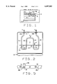
- FIG. 6 illustrates an alternate heating element installation in an oven in which two heating elements are used
- FIG. 7 is an elevational view of an alternate embodiment of the support bar used with the two heating elements
- FIG. 8 is a representation of the expansion of a heating element when an oven is in use
- FIG. 9A and 9B are respective top plan and elevational views of a support bar for use with two heating elements.
- FIG. 10 is a broken elevational view of the support bar illustrating installation and support of a heating element by the support bar.
- an electric stove S is shown in FIG. 1 to include and oven O.
- the oven has a door D to close it, and one or more racks R on which food to be cooked is placed inside the oven.
- the heating element comprises a single piece heating rod which is formed so to have a sinuous shape or contour.
- the heating element has electrical terminals T installed at each end of the rod. The terminals fit into electrical connectors (not shown) which are adjacent a backwall B of the oven.
- the heating element is contoured to have two outer longitudinal segments or reaches S1 and S2 and two inner longitudinal segments or reaches S3 and S4. When installed in the oven, as shown in FIG.
- the length of the heating element is such that it extends substantially the length of the oven from the backwall to the open, front portion of the oven closed by door D.
- FIG. 8 there it is shown that when a current flows through the heating element, causing the element to heat up, the segments S1-S4 of the heating element expand along their length. This expansion is represented by the dashed lines in the drawing. It will be understood that the expansion coefficient for the materials commonly used in a heat exchanger is known. Also, for a heating element contoured as shown in the drawings, the expansion and subsequent contraction of the rod is along the longitudinally extending segments of the element and the apparatus of the present invention is designed to so constrain such movements.
- heating element H is installed in the oven near the top of the oven. As so installed, the heating element is normally maintained in place using an apparatus 10 of the present invention.
- Apparatus 10 is designed to support the heating element so that the element can freely expand and contract along its longitudinal axis and do so repeatedly without damaging either the heating element the electrical connection between the heating element and a control circuit by which current is supplied to the element, and a support for the heating element.
- Apparatus 10 includes a support bar 12 and bracket means 14 for mounting the support bar in the oven.
- the bracket means allows the support bar to be suspended from a top wall W of the oven as shown in FIG. 1.
- the support bar includes an elongate plate 16 which is generally rectangular when viewed in elevation, as shown in FIG. 4B.
- the plate includes series of slots 18a-18d spaced along the length of the plate, again as viewed in FIG. 4B.
- the slots open into the body of plate 16 from the top of the plate.
- the support bar also is available in different lengths to fit in different size ovens and for use with different size heating elements.
- the length of plate 16 is such that it extends substantially across the width of the oven.
- the length of the plate is greater than the width of the heating element as measured between the outer longitudinal segments S1, S2 of the element.
- the support bar is installed so the center of the plate corresponds to the longitudinal axis or centerline of the heating element.
- Slots 18a, 18b are formed in the plate to one side of the centerline, and slots 18c, 18d are formed in the plate to the other side of the centerline.
- Slots 18a and 18c are equidistantly spaced with respect to the centerline, as are slots 18b, 18d.
- Each of the slots is formed such that one end of the slot is open, while the other end of the slot is covered by a portion of the plate.
- each slot is formed in an elongated J shape.
- the height of each slot (including the covered portion of the slot) at least corresponds to the diameter of the respective segment S1-S4 of the heating element to be fitted in the slot.
- the width of each slot is at least twice the diameter of the segments with the width of the covered portion of each slot being at least equal to the diameter of a segment.
- the portion of the slots covered by the plate are the inward ends of the slot.
- Slots 18b and 18d have their outward ends covered by a portion of the plate material. Referring to FIG.
- each of the longitudinal segments S1-S4 of the element are slightly compressed and as so compressed placed in the uncovered portion of the respective slot in which they are received.
- each segment moves as shown by the arrows in FIG. 10 from their solid line position to their dashed line position. In their dashed line positions, each segment now resides in the covered portion of their respective slot.
- each segment S1-S4 of the heating element is constrained to move only parallel to the longitudinal axis of the heating element. As a result, there is no warpage (twisting) in the heating element. This, in turn, produces a more uniform distribution of heat throughout the oven than if the heating element were not so constrained.
- Bracket means 14 comprises a pair of inverted L-shaped brackets 14a, 14b the stem of which is secured to plate 16 in any suitable manner; for example, by a rivet 20.
- the brackets are secured to the top wall of the oven using a rivet or screw (not shown) or other suitable means of attachment.
- the terminal ends of the heating element are fit through respective mounting brackets 22a, 22b which comprise plates having openings therein sized for the rod portion of the heating element to fit. These brackets are secured to the back wall B of the oven; again, in any suitable manner.
- heating element H1 generally corresponds to the heating element H previously described and includes longitudinal segments S1'-S4'.
- Heating element H2, which is installed in the oven so to be coplanar with heating element H1 is a generally U-shaped heating element having longitudinal segments S5 and S6. Both heating elements have electrical terminations T' at their respective ends.
- Heating element H2 is wider than element H1 so, when installed, element H2 encompasses or surrounds element H1 as shown in FIG. 6.
- the longitudinal axis of heating element H1 coincides with that of heating element H2. It will be understood that the heating elements may expand to differing degrees from one another.
- the apparatus of the present invention includes a support bar 52 and a bracket means 54 for mounting the support bar to again be suspended from the top of the oven.
- Support bar 52 comprises a generally rectangular plate 56 having slots 58a-58f spaced along the length of the plate. As before, the slots open into the body of the plate 56 from the top of the plate.
- Plate 56 extends substantially across the width of the oven with the length of the plate being greater than the width of the heating element as now measured between the longitudinal segments S5, S6 of heating element H2.
- the support bar is installed so the center of the plate corresponds to the longitudinal axis or centerline of both heating elements.
- Slots 58a-58c are formed in the plate to one side of the centerline, and slots 58d-58f are on the other side of the centerline.
- Slots 58a and 58d, slots 58b and 58e, slots 58c and 58f are respectively equidistantly spaced from the centerline of the plate.
- Each slot is again J-shaped and formed with one end open and the other end covered by a portion of the plate.
- the height the slots, including their covered portion, corresponds to at least the diameter of the segments of the heating elements.
- the width of each slot is at least twice the diameter of the segments with the width of the covered portion of each slot corresponding to the diameter of the heating elements.
- Bracket means 54 comprises a pair of inverted L-shaped brackets 54a, 54b which are secured to plate 56 by a rivet 60. These brackets are secured to the top wall of the oven. The terminal ends of the heating elements fit through respective mounting brackets 62a, 62b each of which comprises plates having a pair of openings for the terminal end portions of both heating elements to fit. The brackets are secured to the back wall B of the oven.
- a support bar for use in an electric oven for supporting one or more electric heater elements used to cook food set into the oven.
- the support bar is readily mounted inside the oven and supports a heating element so as to allow its full expansion and contraction along a longitudinal axis of the element during a heating cycle.
- the support bar has a plurality of spaced slots in which portions of respective segments of the heating element are received, the slots being open at one end for insertion of the heating element, and closed at the other end. This enclosed end of the slots engage respective segments of a heating element to control its movement in the longitudinal direction of the heating element.
- the heating element is readily removable to facilitate installation of a replacement element.
- the support bar can support two, separate heating elements and can support both elements even though they may expand or contract to different degrees.
- the support bar is available in different sizes for use with different size heating elements, and the support bars provide a low cost, dependable way to install electrical heating elements in ovens.
Abstract
Description
Claims (19)
Priority Applications (1)
| Application Number | Priority Date | Filing Date | Title |
|---|---|---|---|
| US09/005,088 US6097003A (en) | 1998-01-09 | 1998-01-09 | Support bar attachment for an electric heater element |
Applications Claiming Priority (1)
| Application Number | Priority Date | Filing Date | Title |
|---|---|---|---|
| US09/005,088 US6097003A (en) | 1998-01-09 | 1998-01-09 | Support bar attachment for an electric heater element |
Publications (1)
| Publication Number | Publication Date |
|---|---|
| US6097003A true US6097003A (en) | 2000-08-01 |
Family
ID=21714116
Family Applications (1)
| Application Number | Title | Priority Date | Filing Date |
|---|---|---|---|
| US09/005,088 Expired - Lifetime US6097003A (en) | 1998-01-09 | 1998-01-09 | Support bar attachment for an electric heater element |
Country Status (1)
| Country | Link |
|---|---|
| US (1) | US6097003A (en) |
Cited By (18)
| Publication number | Priority date | Publication date | Assignee | Title |
|---|---|---|---|---|
| US6232581B1 (en) * | 1997-12-12 | 2001-05-15 | I.R.C.A. S.P.A. Inoustria Resistenze Corazzate E Affini | Connection flange for an armoured resistance element |
| US6359262B1 (en) | 2000-10-26 | 2002-03-19 | Emerson Electric Co. | Support bracket for heater element in bake oven |
| US6433318B2 (en) * | 2000-08-11 | 2002-08-13 | Michael Danko | Electric heater assembly with in-line thermostat |
| WO2002089527A2 (en) * | 2001-04-27 | 2002-11-07 | Tutco, Inc. | Method and apparatus for mounting a heater thermostat and temperature sensitive fuse |
| WO2003049501A2 (en) * | 2001-11-30 | 2003-06-12 | Tutco, Inc. | Improved insulator support structure for a heater assembly |
| GB2452336A (en) * | 2007-09-03 | 2009-03-04 | James Hattrick | Clamping means for cooker hotplate |
| US20120281975A1 (en) * | 2009-08-21 | 2012-11-08 | Von Ardenne Anlagentechnik Gmbh | Surface heating device for a substrate treatment device and substrate treatment device |
| US20130306051A1 (en) * | 2012-05-16 | 2013-11-21 | Bsh Home Appliances Corporation | Home appliance with unitary bake element retainer |
| ITPR20130086A1 (en) * | 2013-10-31 | 2015-05-01 | Indesit Co Spa | OVEN. |
| ITTO20131098A1 (en) * | 2013-12-31 | 2015-07-01 | Indesit Co Spa | METHOD FOR FIXING A RESISTANCE TO A MUFFLE AND OVEN MADE ACCORDING TO THIS METHOD |
| US20160327276A1 (en) * | 2015-05-08 | 2016-11-10 | Lg Electronics Inc. | Cooking appliance |
| EP2372249B1 (en) * | 2010-04-01 | 2017-10-11 | Electrolux Home Products Corporation N.V. | Oven |
| USD819386S1 (en) | 2016-02-11 | 2018-06-05 | Whirlpool Corporation | Oven |
| USD827356S1 (en) | 2016-02-11 | 2018-09-04 | Whirlpool Corporation | Oven |
| JP2019179704A (en) * | 2018-03-30 | 2019-10-17 | 株式会社日立プラントコンストラクション | Electric heater mounting structure |
| WO2020078698A1 (en) | 2018-10-15 | 2020-04-23 | Arcelik Anonim Sirketi | An oven comprising a heater support element |
| USD909811S1 (en) | 2016-12-30 | 2021-02-09 | Whirlpool Corporation | Panel for an oven |
| US11454401B2 (en) * | 2019-01-11 | 2022-09-27 | Lg Electronics Inc. | Cooking appliance |
Citations (8)
| Publication number | Priority date | Publication date | Assignee | Title |
|---|---|---|---|---|
| US2799766A (en) * | 1955-03-31 | 1957-07-16 | Tuttle Electric Products Inc | Electric heating unit |
| CA626997A (en) * | 1961-09-05 | E. Ammerman George | Magnetically supported heater assembly | |
| US3005082A (en) * | 1958-04-28 | 1961-10-17 | Wiegand Co Edwin L | Electric heater assembly for ovens |
| US3154669A (en) * | 1959-10-19 | 1964-10-27 | Gen Electric | Electric heater and support assembly |
| DE1565683A1 (en) * | 1966-09-17 | 1970-03-05 | Licentia Gmbh | Device for holding the heating element |
| US3770939A (en) * | 1972-09-19 | 1973-11-06 | Emerson Electric Co | Electric heating assemblies |
| US4272638A (en) * | 1979-03-16 | 1981-06-09 | Johns-Manville Corporation | Heater element supports for use with fibrous block insulations |
| US4392052A (en) * | 1981-04-03 | 1983-07-05 | Bulten-Kanthal Ab | Device for carrying electrical resistance elements |
-
1998
- 1998-01-09 US US09/005,088 patent/US6097003A/en not_active Expired - Lifetime
Patent Citations (8)
| Publication number | Priority date | Publication date | Assignee | Title |
|---|---|---|---|---|
| CA626997A (en) * | 1961-09-05 | E. Ammerman George | Magnetically supported heater assembly | |
| US2799766A (en) * | 1955-03-31 | 1957-07-16 | Tuttle Electric Products Inc | Electric heating unit |
| US3005082A (en) * | 1958-04-28 | 1961-10-17 | Wiegand Co Edwin L | Electric heater assembly for ovens |
| US3154669A (en) * | 1959-10-19 | 1964-10-27 | Gen Electric | Electric heater and support assembly |
| DE1565683A1 (en) * | 1966-09-17 | 1970-03-05 | Licentia Gmbh | Device for holding the heating element |
| US3770939A (en) * | 1972-09-19 | 1973-11-06 | Emerson Electric Co | Electric heating assemblies |
| US4272638A (en) * | 1979-03-16 | 1981-06-09 | Johns-Manville Corporation | Heater element supports for use with fibrous block insulations |
| US4392052A (en) * | 1981-04-03 | 1983-07-05 | Bulten-Kanthal Ab | Device for carrying electrical resistance elements |
Cited By (34)
| Publication number | Priority date | Publication date | Assignee | Title |
|---|---|---|---|---|
| US6232581B1 (en) * | 1997-12-12 | 2001-05-15 | I.R.C.A. S.P.A. Inoustria Resistenze Corazzate E Affini | Connection flange for an armoured resistance element |
| US6433318B2 (en) * | 2000-08-11 | 2002-08-13 | Michael Danko | Electric heater assembly with in-line thermostat |
| US6359262B1 (en) | 2000-10-26 | 2002-03-19 | Emerson Electric Co. | Support bracket for heater element in bake oven |
| US6723968B2 (en) | 2001-04-27 | 2004-04-20 | Tutco, Inc. | Conductive U-shaped jumper strap and method of use |
| WO2002089527A2 (en) * | 2001-04-27 | 2002-11-07 | Tutco, Inc. | Method and apparatus for mounting a heater thermostat and temperature sensitive fuse |
| WO2002089527A3 (en) * | 2001-04-27 | 2003-02-20 | Tutco Inc | Method and apparatus for mounting a heater thermostat and temperature sensitive fuse |
| US6593554B2 (en) | 2001-04-27 | 2003-07-15 | Tutco, Inc. | Method and apparatus for mounting a heater thermostat and temperature sensitive fuse |
| CN1324928C (en) * | 2001-04-27 | 2007-07-04 | 图特科有限公司 | Method and apparatus for mounting heater thermostat and temp sensitive fuse |
| KR100817756B1 (en) * | 2001-05-11 | 2008-03-31 | 투트코 인코포레이티드 | Electric Heater Assembly With In-Line Thermostat |
| US6624398B2 (en) | 2001-11-30 | 2003-09-23 | Tutco, Inc. | Insulator support structure for a heater assembly |
| CN100338971C (en) * | 2001-11-30 | 2007-09-19 | 图特科有限公司 | Improved insulator support structure for heater assembly |
| KR100771717B1 (en) * | 2001-11-30 | 2007-10-30 | 투트코 인코포레이티드 | Improved insulator support structure for a heater assembly |
| WO2003049501A3 (en) * | 2001-11-30 | 2003-08-21 | Tutco Inc | Improved insulator support structure for a heater assembly |
| WO2003049501A2 (en) * | 2001-11-30 | 2003-06-12 | Tutco, Inc. | Improved insulator support structure for a heater assembly |
| GB2452336A (en) * | 2007-09-03 | 2009-03-04 | James Hattrick | Clamping means for cooker hotplate |
| US20120281975A1 (en) * | 2009-08-21 | 2012-11-08 | Von Ardenne Anlagentechnik Gmbh | Surface heating device for a substrate treatment device and substrate treatment device |
| US8718456B2 (en) * | 2009-08-21 | 2014-05-06 | Von Ardenne Anlagentechnik Gmbh | Surface heating device for a substrate treatment device and substrate treatment device |
| EP2372249B1 (en) * | 2010-04-01 | 2017-10-11 | Electrolux Home Products Corporation N.V. | Oven |
| US20130306051A1 (en) * | 2012-05-16 | 2013-11-21 | Bsh Home Appliances Corporation | Home appliance with unitary bake element retainer |
| US9057525B2 (en) * | 2012-05-16 | 2015-06-16 | Bsh Home Appliances Corporation | Home appliance with unitary bake element retainer |
| ITPR20130086A1 (en) * | 2013-10-31 | 2015-05-01 | Indesit Co Spa | OVEN. |
| CN105683657A (en) * | 2013-10-31 | 2016-06-15 | 英德斯特股份公司 | Cooking oven |
| US20160252255A1 (en) * | 2013-10-31 | 2016-09-01 | Whirlpool Corporation | Oven |
| WO2015063656A1 (en) * | 2013-10-31 | 2015-05-07 | Indesit Company S.P.A. | Cooking oven |
| ITTO20131098A1 (en) * | 2013-12-31 | 2015-07-01 | Indesit Co Spa | METHOD FOR FIXING A RESISTANCE TO A MUFFLE AND OVEN MADE ACCORDING TO THIS METHOD |
| WO2015101889A1 (en) * | 2013-12-31 | 2015-07-09 | Indesit Company S.P.A. | Method for fastening a resistor to a muffle and oven made according thereto |
| US20160327276A1 (en) * | 2015-05-08 | 2016-11-10 | Lg Electronics Inc. | Cooking appliance |
| US10364990B2 (en) * | 2015-05-08 | 2019-07-30 | Lg Electronics Inc. | Cooking appliance |
| USD819386S1 (en) | 2016-02-11 | 2018-06-05 | Whirlpool Corporation | Oven |
| USD827356S1 (en) | 2016-02-11 | 2018-09-04 | Whirlpool Corporation | Oven |
| USD909811S1 (en) | 2016-12-30 | 2021-02-09 | Whirlpool Corporation | Panel for an oven |
| JP2019179704A (en) * | 2018-03-30 | 2019-10-17 | 株式会社日立プラントコンストラクション | Electric heater mounting structure |
| WO2020078698A1 (en) | 2018-10-15 | 2020-04-23 | Arcelik Anonim Sirketi | An oven comprising a heater support element |
| US11454401B2 (en) * | 2019-01-11 | 2022-09-27 | Lg Electronics Inc. | Cooking appliance |
Similar Documents
| Publication | Publication Date | Title |
|---|---|---|
| US6097003A (en) | Support bar attachment for an electric heater element | |
| US7285757B2 (en) | Bottom electric heating element systems and ovens | |
| US20130334197A1 (en) | Electric oven and method for servicing same | |
| EP2032005B1 (en) | Rack assembly | |
| CN101666513A (en) | Cooker | |
| ITMI970778A1 (en) | ELECTRIC COOKING APPLIANCE IN PARTICULAR FRYER | |
| US5134270A (en) | Heater assembly for use in clothes dryers | |
| US5552581A (en) | Defrost heater for cooling appliance | |
| CA2776097C (en) | Home appliance with unitary broil element mount and reflector | |
| US6359262B1 (en) | Support bracket for heater element in bake oven | |
| KR101222738B1 (en) | Electric oven | |
| WO2020078698A1 (en) | An oven comprising a heater support element | |
| WO2009083389A1 (en) | A cooktop | |
| EP2746671B1 (en) | Cooking oven comprising a heating element fastened with fastening means | |
| KR200440652Y1 (en) | Electric roaster | |
| US3296417A (en) | Hinging means for oven heating element | |
| CA2475728C (en) | Standoff for use with uncoiled bare wire and insulated runs of an open coil electric resistance heater, method of use, and an open coil resistance heater using the standoff | |
| EP1050260B1 (en) | Shell structure for a heating appliance, and method of manufacturing heating appliance including same | |
| CN208419611U (en) | A kind of high temperature box type resistance furnace | |
| WO2008080923A1 (en) | Oven comprising a pivotable frame used as tray support or grill | |
| JP2539825Y2 (en) | High frequency heating equipment | |
| US20130306051A1 (en) | Home appliance with unitary bake element retainer | |
| CN218552115U (en) | Food heating equipment | |
| CN214387237U (en) | Baking tray and oven thereof | |
| CN217659350U (en) | Grill for electric oven |
Legal Events
| Date | Code | Title | Description |
|---|---|---|---|
| AS | Assignment |
Owner name: EMERSON ELECTRIC CO., MISSOURI Free format text: ASSIGNMENT OF ASSIGNORS INTEREST;ASSIGNORS:MARKUM, RANDALL;SPRINGER, STACY V.;WARNER, JOHN H.;REEL/FRAME:008950/0239 Effective date: 19980107 |
|
| STCF | Information on status: patent grant |
Free format text: PATENTED CASE |
|
| CC | Certificate of correction | ||
| FEPP | Fee payment procedure |
Free format text: PAYER NUMBER DE-ASSIGNED (ORIGINAL EVENT CODE: RMPN); ENTITY STATUS OF PATENT OWNER: LARGE ENTITY Free format text: PAYOR NUMBER ASSIGNED (ORIGINAL EVENT CODE: ASPN); ENTITY STATUS OF PATENT OWNER: LARGE ENTITY |
|
| FPAY | Fee payment |
Year of fee payment: 4 |
|
| FPAY | Fee payment |
Year of fee payment: 8 |
|
| REMI | Maintenance fee reminder mailed | ||
| AS | Assignment |
Owner name: BACKER EHP INC., TENNESSEE Free format text: ASSIGNMENT OF ASSIGNORS INTEREST;ASSIGNOR:EMERSON ELECTRIC CO.;REEL/FRAME:027407/0507 Effective date: 20110912 |
|
| FPAY | Fee payment |
Year of fee payment: 12 |