US6095729A - Spindle extension for milling machine - Google Patents

Spindle extension for milling machine Download PDF

Info

Publication number
US6095729A
US6095729A US09/207,953 US20795398A US6095729A US 6095729 A US6095729 A US 6095729A US 20795398 A US20795398 A US 20795398A US 6095729 A US6095729 A US 6095729A
Authority
US
United States
Prior art keywords
arbor
housing
spindle extension
spindle
outer race
Prior art date
Legal status (The legal status is an assumption and is not a legal conclusion. Google has not performed a legal analysis and makes no representation as to the accuracy of the status listed.)
Expired - Fee Related
Application number
US09/207,953
Inventor
James P. Pattison
Sukhminder S. Grewal
Douglas R. Smith
Current Assignee (The listed assignees may be inaccurate. Google has not performed a legal analysis and makes no representation or warranty as to the accuracy of the list.)
General Electric Co
Original Assignee
General Electric Co
Priority date (The priority date is an assumption and is not a legal conclusion. Google has not performed a legal analysis and makes no representation as to the accuracy of the date listed.)
Filing date
Publication date
Application filed by General Electric Co filed Critical General Electric Co
Priority to US09/207,953 priority Critical patent/US6095729A/en
Assigned to GENERAL ELECTRIC COMPANY reassignment GENERAL ELECTRIC COMPANY ASSIGNMENT OF ASSIGNORS INTEREST (SEE DOCUMENT FOR DETAILS). Assignors: GREWAL, SUKHMINDER S., PATTISON, JAMES P., SMITH, DOUGLAS R.
Application granted granted Critical
Publication of US6095729A publication Critical patent/US6095729A/en
Anticipated expiration legal-status Critical
Expired - Fee Related legal-status Critical Current

Links

Images

Classifications

    • BPERFORMING OPERATIONS; TRANSPORTING
    • B23MACHINE TOOLS; METAL-WORKING NOT OTHERWISE PROVIDED FOR
    • B23QDETAILS, COMPONENTS, OR ACCESSORIES FOR MACHINE TOOLS, e.g. ARRANGEMENTS FOR COPYING OR CONTROLLING; MACHINE TOOLS IN GENERAL CHARACTERISED BY THE CONSTRUCTION OF PARTICULAR DETAILS OR COMPONENTS; COMBINATIONS OR ASSOCIATIONS OF METAL-WORKING MACHINES, NOT DIRECTED TO A PARTICULAR RESULT
    • B23Q1/00Members which are comprised in the general build-up of a form of machine, particularly relatively large fixed members
    • B23Q1/70Stationary or movable members for carrying working-spindles for attachment of tools or work
    • B23Q1/703Spindle extensions
    • YGENERAL TAGGING OF NEW TECHNOLOGICAL DEVELOPMENTS; GENERAL TAGGING OF CROSS-SECTIONAL TECHNOLOGIES SPANNING OVER SEVERAL SECTIONS OF THE IPC; TECHNICAL SUBJECTS COVERED BY FORMER USPC CROSS-REFERENCE ART COLLECTIONS [XRACs] AND DIGESTS
    • Y10TECHNICAL SUBJECTS COVERED BY FORMER USPC
    • Y10TTECHNICAL SUBJECTS COVERED BY FORMER US CLASSIFICATION
    • Y10T409/00Gear cutting, milling, or planing
    • Y10T409/30Milling
    • Y10T409/30448Milling with detachable or auxiliary cutter support to convert cutting action
    • YGENERAL TAGGING OF NEW TECHNOLOGICAL DEVELOPMENTS; GENERAL TAGGING OF CROSS-SECTIONAL TECHNOLOGIES SPANNING OVER SEVERAL SECTIONS OF THE IPC; TECHNICAL SUBJECTS COVERED BY FORMER USPC CROSS-REFERENCE ART COLLECTIONS [XRACs] AND DIGESTS
    • Y10TECHNICAL SUBJECTS COVERED BY FORMER USPC
    • Y10TTECHNICAL SUBJECTS COVERED BY FORMER US CLASSIFICATION
    • Y10T409/00Gear cutting, milling, or planing
    • Y10T409/30Milling
    • Y10T409/309296Detachable or repositionable tool head
    • YGENERAL TAGGING OF NEW TECHNOLOGICAL DEVELOPMENTS; GENERAL TAGGING OF CROSS-SECTIONAL TECHNOLOGIES SPANNING OVER SEVERAL SECTIONS OF THE IPC; TECHNICAL SUBJECTS COVERED BY FORMER USPC CROSS-REFERENCE ART COLLECTIONS [XRACs] AND DIGESTS
    • Y10TECHNICAL SUBJECTS COVERED BY FORMER USPC
    • Y10TTECHNICAL SUBJECTS COVERED BY FORMER US CLASSIFICATION
    • Y10T409/00Gear cutting, milling, or planing
    • Y10T409/30Milling
    • Y10T409/309352Cutter spindle or spindle support
    • Y10T409/309408Cutter spindle or spindle support with cutter holder

Landscapes

  • Engineering & Computer Science (AREA)
  • Mechanical Engineering (AREA)
  • Milling Processes (AREA)

Abstract

Tool extension and stability in milling machines is enhanced by providing a spindle extension having a housing attached to the mill head and an arbor rotatively mounted in a bore formed in the housing. The arbor, which is significantly longer than conventional arbors, is supported by first and second bearing assemblies and includes a substantially cylindrical body portion with an integral shank formed on one end thereof for connecting the arbor to a machine tool spindle. A cutting tool is attached to the other end of the arbor.

Description

BACKGROUND OF THE INVENTION
This invention relates generally to spindle extensions for milling machines and more particularly to a spindle extension having a supported arbor.
Milling machines are well known devices used for a wide variety of machining operations. A typical milling machine includes a mill head provided with a spindle that rotates with respect to the mill head. A cutting tool is attached to the spindle to perform work on a workpiece. A common prior art approach for fitting the tool to the spindle includes inserting a tapered shank of the tool into a tapered hole formed in the spindle. A retention knob provided on the shank is grasped by the milling machine's conventional draw bar assembly, which pulls the shank into the spindle to firmly attach the tool to the spindle. One problem with this arrangement is that standard cutting tools are too short to accommodate deep cavities required in some workpieces. While spindle extensions are available, these typically provide relatively limited extensions in the reach of the milling machine.
One known spindle extension comprises an arbor provided on one end with a tapered shank sized to fit the tapered hole of a standard milling machine spindle. The tapered shank is received in the tapered hole in order to connect the arbor for rotation with the spindle in the same manner that a cutting tool is conventionally connected to the spindle. The cutting tool is then attached to the end of the arbor opposite the spindle and is thus displaced from the spindle a distance equal to the length of the arbor. However, with this type of spindle extension, the arbor is not supported in any way other than by the tapered shank spindle connection. This results in a cantilevered arrangement that is susceptible to excessive flexure. Accordingly, such conventional spindle extensions are limited to arbor lengths of about six inches, and such extensions do not function well in high speed, heavy cutting machining operations. At greater lengths, the arbor and/or the tool tend to experience instability that can result in lack of dimensional control, poor surface finish and tool failure.
Accordingly, there is a need for a milling machine spindle extension that provides considerably greater tool reach in high speed milling machines in a stable manner.
SUMMARY OF THE INVENTION
The above-mentioned needs are met by the present invention which provides a milling machine spindle extension having a housing attached to the mill head and an arbor rotatively mounted in a bore formed in the housing. The arbor, which is significantly longer than conventional arbors, is supported by first and second bearing assemblies and includes a substantially cylindrical body portion with an integral shank formed on one end thereof for connecting the arbor to a machine tool spindle. The other end of the arbor includes a means for attaching a cutting tool.
Other objects and advantages of the present invention will become apparent upon reading the following detailed description and the appended claims with reference to the accompanying drawings.
DESCRIPTION OF THE DRAWINGS
The subject matter which is regarded as the invention is particularly pointed out and distinctly claimed in the concluding part of the specification. The invention, however, may be best understood by reference to the following description taken in conjunction with the accompanying drawing figures in which:
FIG. 1 is a partial side view of a milling machine having the spindle extension of the present invention.
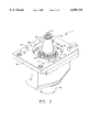
FIG. 2 is a perspective view of the spindle extension of the present invention.
FIG. 3 is a sectional view of the spindle extension of FIG. 2.
FIG. 4 is another perspective view of the spindle extension of the present invention.
DETAILED DESCRIPTION OF THE INVENTION
Referring to the drawings wherein identical reference numerals denote the same elements throughout the various views, FIG. 1 shows a portion of a milling machine 10 having a spindle extension 12 of the present invention. Milling machine 10 includes a mill head 14 moveable about and along multiple axes and a mill table 16 for supporting a workpiece 18 to be worked on. Spindle extension 12 is attached to mill head 14 and carries a cutting tool 20 for machining within a deep cavity formed by workpiece 18.
Turning now to FIGS. 2-4, spindle extension 12 is shown in greater detail. Spindle extension 12 includes a stationary housing 22 that is fixedly attached to mill head 14. A substantially cylindrical bore 24 (FIG. 3) is formed through housing 22. Bore 24 extends from the proximal end 26 of housing 22 to the distal end 28 of housing 22. A mounting flange 30 is formed on proximal end 26 for attaching housing 22 to mill head 14 in a manner that will be subsequently described.
An arbor 32 is mounted in bore 24 for rotation about its longitudinal axis. Arbor 32 includes a substantially cylindrical body portion 34 having a shank 36 integrally formed on one end and a threaded hole 38 formed in the other end. Threaded hole 38 is coaxial with the longitudinal axis of arbor 32 and, together with a screw 39, provides a means for attaching cutting tool 20 to spindle extension 12. As best shown in FIG. 4, a pair of drive lugs 41 is attached to arbor 32 adjacent to threaded hole 38. Drive lugs 41 are received in notches (not shown) formed in cutting tool 20 so as to prevent rotation of tool 20 with respect to arbor 32 during cutting operations. Shank 36 is adapted to be received within a hole 40 of the milling machine spindle 42 (FIG. 3) rotatively mounted in mill head 14. Shank 36 and hole 40 are preferably, although not necessarily, tapered. A retention knob 44 is affixed to the end of tapered shank 36 and grasped by the milling machine power draw bar apparatus (not shown) such that tapered shank 36, and hence arbor 32, is pulled into firm engagement with spindle 42. A drive flange 46 is formed on arbor 32 at the base of tapered shank 36. As seen in FIG. 2, drive flange 46 has a pair of notches 48 formed therein for receiving projections (not shown) formed on the lower end of spindle 42 so as to positively transmit the rotation of spindle 42 to arbor 32.
Referring to FIG. 3, it is seen that arbor 32 is rotatively supported in bore 24 by a first, or distal, bearing assembly 50 and a second, or proximal, bearing assembly 52. First bearing assembly 50, located adjacent to distal end 28 of housing 22, includes an outer ring-shaped race 54 disposed in a first annular recess 56 formed in bore 24 and an inner ring-shaped race 58 fixed to the outer surface of arbor 32. A first cap ring 60 is attached to distal end 28 of housing 22 so as to encircle arbor 32 and close off the open end of bore 24 and retain outer race 54 in recess 56. Cap ring 60 supports a first shaft seal 62 which slidingly engages arbor 32 to seal the interior of housing 22 from influx of machining debris. One or more sets of circumferentially spaced rollers 64 are disposed between outer and inner races 54 and 58 with their individual longitudinal axes arranged parallel with the longitudinal axis of arbor 32. Preferably, at least two sets of rollers 64, as shown in FIG. 3, are provided. It should be noted however, that when using two or more sets, rollers 64 are staggered between adjacent sets. That is, the rollers of one set are not circumferentially aligned with the rollers of another set.
Each set of rollers 64 is disposed in a respective annular recess 66 formed in the inner surface of outer race 54. Consequently, rollers 64 are set into outer race 54 so as to prevent relative axial motion between rollers 64 and outer race 54. Conversely, rollers 64 are not set into inner race 58 so that relative axial motion between rollers 64 and inner race 58 is permitted. This arrangement accommodates the axial displacement of arbor 32 with respect to housing 22 that occurs when retention knob 44 is pulled into tapered hole 40 by the milling machine power draw bar apparatus to attach arbor 32 to spindle 42. That is, when arbor 32 is pulled into firm engagement with spindle 42, inner race 58 slides axially along rollers 64, allowing arbor 32 to move axially with respect to housing 22, which is secured directly to mill head 14. And when arbor 32 is subsequently released from engagement with spindle 42, inner race 58 slides along rollers 64 in the opposite axial direction.
Second bearing assembly 52, located adjacent to proximal end 26 of housing 22, includes an outer ring-shaped race 68 disposed in a second annular recess 70 formed in bore 24 and an inner ring-shaped race 72 fixed to the outer surface of arbor 32. Inner race 72 is held on arbor 32 against relative axial movement by a retainer ring 74 screwed onto threads 76 formed on the outer surface of arbor 32. A second cap ring 78 is attached toproximal end 26 of housing 22 by a number of bolts 80 so as to encircle arbor 32 and close off the open end of bore 24. Cap ring 78 supports a second shaft seal 82 which slidingly engages arbor 32 to seal the interior of housing 22 from influx of machining debris. A set of circumferentially spaced ball bearings 84 is disposed between outer and inner races 68 and 72. Inner race 72 includes an annular recess 86 that prevents any relative axial motion between ball bearings 84 and inner race 72, while outer race 68 includes an annular recess 88 that prevents relative axial motion between ball bearings 84 and outer race 68 in one axial direction (upward as viewed in FIG. 3) but permits relative axial motion between ball bearings 84 and outer race 68 in the other axial direction.
Outer race 68 is biased in that other axial direction (downward as viewed in FIG. 3) by a wave spring 90 and a spacer assembly 92. Spacer assembly 92 is slidingly disposed in a third annular recess 94 formed in bore 24, which is adjacent to and slightly deeper than second annular recess 70. Wave spring 90 is disposed between cap ring 78 and spacer assembly 92 in a compressed state so as to tend to push spacer assembly 92 away from cap ring 78. The other end of spacer assembly 92 abuts against outer race 68 so that the downward bias of wave spring 90 is transmitted to outer race 68. Thus, when arbor 32 is pulled into firm engagement with spindle 42 by the milling machine power draw bar apparatus, inner race 72 and ball bearings 84 are moved axially as well. The ball bearings 84 abut against the closed side of annular recess 88 and force outer race 68 upwards against the force of wave spring 90, thereby preloading second bearing assembly 52 to the proper value for smooth running. When arbor 32 is released from engagement with spindle 42, inner race 72 and ball bearings 84 move in the opposite (downward) axial direction. Outer race 68 is forced downward due to the force of wave spring 90. Accordingly, second bearing assembly 52 is able to accommodate the axial displacement of arbor 32 with respect to housing 22.
Spacer assembly 92 includes a first spacer 93 located next to outer race 68 and a second spacer 95 placed in contact with wave spring 90. This two piece arrangement facilitates construction of second bearing assembly 52. That is, during assembly, first spacer 93 is initially placed into position against outer race 68 before retainer ring 74 is secured to arbor 32. Then, after retainer ring 74 has been screwed onto threads 76, second spacer 95 is installed.
Because of the support provided by housing 22 and first and second bearing assemblies 50 and 52, spindle extension 12 can provide significantly greater extension than the prior art devices without experiencing tool instability. Specifically, cylindrical body portion 34 of arbor 32 (i.e., the length of arbor from drive flange 46 to tool 20) can be in the range of about 10-20 inches long.
As mentioned above, housing 22 is fixedly attached to mill head 14. While housing 22 can be directly attached to mill head 14, it is preferably attached via a base plate 96. As best seen in FIG. 2, base plate 96 has a central opening 98 to accommodate tapered shank 36 and is attached to the underside of mill head 14 by a number of bolts 100. Housing 22 is then attached to base plate 96 by additional bolts 102 that extend through mounting flange 30 and threadingly engage base plate 96. Base plate 96 compensates for the fact that the underside of a mill head is typically not square with respect to the longitudinal axis of the mill head's spindle. Specifically, the surface of base plate 96 that contacts mill head 14 can be machined so that when base plate 96 is attached to mill head 14, the other surface of base plate 96 is perpendicular to the spindle axis. Thus, a single spindle extension 12 can be easily interchanged between a number of milling machines by simply providing each milling machine with its own base plate.
The foregoing has described a spindle extension having a supported arbor so as to stabilize the cutting tool at extended distances from the spindle. While specific embodiments of the present invention have been described, it will be apparent to those skilled in the art that various modifications thereto can be made without departing from the spirit and scope of the invention as defined in the appended claims.

Claims (13)

What is claimed is:
1. A spindle extension for a milling machine having a mill head and a spindle rotatively mounted in said mill head, said spindle extension comprising:
a housing attached to said mill head and having a bore formed therein;
an arbor rotatively mounted in said bore, said arbor including a substantially cylindrical body portion with an integral shank formed on one end and a means for attaching a tool provided on the other end; and
at least one bearing assembly disposed between said arbor and said housing, wherein said bearing assembly permits displacement of said arbor relative to said housing along the longitudinal axis of said arbor.
2. The spindle extension of claim 1 comprising first and second bearing assemblies disposed between said arbor and said housing, both of said first and second bearing assemblies permitting displacement of said arbor relative to said housing along the longitudinal axis of said arbor.
3. The spindle extension of claim 2 wherein said first bearing assembly comprises an outer race fixed to said housing, an inner race fixed to said arbor, and a set of rollers disposed between said outer race and said inner race, said rollers being retained against relative axial movement with respect to said outer race but not with respect to said inner race.
4. The spindle extension of claim 3 further comprising a second set of rollers disposed between said outer race and said inner race, said second set of rollers being retained against relative axial movement with respect to said outer race but not with respect to said inner race.
5. The spindle extension of claim 2 wherein said second bearing assembly comprises an outer race slidably disposed in said housing, an inner race fixed to said arbor, a spring situated to bias said outer race towards one end of said housing, and a set of ball bearings disposed between said outer race and said inner race.
6. The spindle extension of claim 5 further comprising a spacer slidably disposed in said housing between said outer race and said spring.
7. The spindle extension of claim 1 wherein said substantially cylindrical body portion is greater than six inches long.
8. The spindle extension of claim 7 wherein said substantially cylindrical body portion is at least about ten inches long.
9. The spindle extension of claim 1 further comprising a base plate disposed between said housing and said mill head.
10. The spindle extension of claim 1 further comprising a cap ring attached to one end of said housing and a shaft seal supported by said cap ring and slidingly engaging said arbor.
11. The spindle extension of claim 10 further comprising a second cap ring attached to another end of said housing and a second shaft seal supported by said second cap ring and slidingly engaging said arbor.
12. The spindle extension of claim 1 wherein said shank is tapered.
13. The spindle extension of claim 1 further comprising at least one drive lug attached to said arbor adjacent to said means for attaching a tool.
US09/207,953 1998-12-09 1998-12-09 Spindle extension for milling machine Expired - Fee Related US6095729A (en)

Priority Applications (1)

Application Number Priority Date Filing Date Title
US09/207,953 US6095729A (en) 1998-12-09 1998-12-09 Spindle extension for milling machine

Applications Claiming Priority (1)

Application Number Priority Date Filing Date Title
US09/207,953 US6095729A (en) 1998-12-09 1998-12-09 Spindle extension for milling machine

Publications (1)

Publication Number Publication Date
US6095729A true US6095729A (en) 2000-08-01

Family

ID=22772655

Family Applications (1)

Application Number Title Priority Date Filing Date
US09/207,953 Expired - Fee Related US6095729A (en) 1998-12-09 1998-12-09 Spindle extension for milling machine

Country Status (1)

Country Link
US (1) US6095729A (en)

Cited By (7)

* Cited by examiner, † Cited by third party
Publication number Priority date Publication date Assignee Title
US6254321B1 (en) * 1996-09-06 2001-07-03 Bjorn Lind Finance & Property Arrangement relating to high-speed tools
US20040074074A1 (en) * 2001-11-26 2004-04-22 Yasuhiko Kikkawa Spindle device of machine tool and method of replacing spindle
US6782779B2 (en) 2001-09-21 2004-08-31 General Electric Co. Method and apparatus for machining turbine component internals
US20050013926A1 (en) * 2003-07-17 2005-01-20 General Electric Company Robotic pen
US8727633B2 (en) * 2009-07-07 2014-05-20 Agco A/S Bearing support assembly
WO2019109117A1 (en) * 2017-12-05 2019-06-13 Fill Gesellschaft M.B.H. Machine tool, and method for machining a workpiece
CN112453440A (en) * 2019-09-09 2021-03-09 李佩玲 Rotating shaft structure of processing machine main shaft

Citations (15)

* Cited by examiner, † Cited by third party
Publication number Priority date Publication date Assignee Title
US2915549A (en) * 1958-09-24 1959-12-01 Dow Chemical Co Process for preparing 1-cyano-2-chloroethyl acetate
US3164063A (en) * 1963-03-11 1965-01-05 J & M Co Ltd Extension milling head
SU645778A2 (en) * 1977-09-01 1979-02-10 Особое Конструкторское Бюро Станкостроения High-speed tool head
JPS6020832A (en) * 1983-07-12 1985-02-02 Fuji Seikou Kk Holder for revolving cutting tool
SU1181784A1 (en) * 1984-05-14 1985-09-30 Ульяновское Головное Специальное Конструкторское Бюро Тяжелых И Фрезерных Станков Spindie assembly
US4548532A (en) * 1982-04-10 1985-10-22 Toshiba Kikai Kabushiki Kaisha Attachments for fitting tools to spindles
US4557645A (en) * 1984-02-27 1985-12-10 Colt Industries Operating Corporation Tooling attachment adaptor assembly
JPS62120956A (en) * 1985-11-15 1987-06-02 Kitamura Kikai Kk Universal head for machine tool
JPS62251037A (en) * 1986-04-21 1987-10-31 Toshiba Tungaloy Co Ltd Module tool
US4815903A (en) * 1987-08-07 1989-03-28 Skidmore Sr Samuel C Auxiliary support bearing for a milling machine head
US5027682A (en) * 1989-02-27 1991-07-02 Toshiba Kikai Kabushiki Kaisha Attachment mounting mechanism in a machine tool
US5033921A (en) * 1989-02-10 1991-07-23 Koyo Seiko Co., Ltd. Traction drive tool adapter
US5322494A (en) * 1992-01-22 1994-06-21 The Ingersoll Milling Machine Company High speed spindle unit and driver
US5342155A (en) * 1993-05-26 1994-08-30 Harroun Enterprises Spindle extension with self-contained pull-stud draw bar assembly
US5632580A (en) * 1995-03-31 1997-05-27 The United States Of America As Represented By The Secretary Of The Navy Milling machine extension

Patent Citations (15)

* Cited by examiner, † Cited by third party
Publication number Priority date Publication date Assignee Title
US2915549A (en) * 1958-09-24 1959-12-01 Dow Chemical Co Process for preparing 1-cyano-2-chloroethyl acetate
US3164063A (en) * 1963-03-11 1965-01-05 J & M Co Ltd Extension milling head
SU645778A2 (en) * 1977-09-01 1979-02-10 Особое Конструкторское Бюро Станкостроения High-speed tool head
US4548532A (en) * 1982-04-10 1985-10-22 Toshiba Kikai Kabushiki Kaisha Attachments for fitting tools to spindles
JPS6020832A (en) * 1983-07-12 1985-02-02 Fuji Seikou Kk Holder for revolving cutting tool
US4557645A (en) * 1984-02-27 1985-12-10 Colt Industries Operating Corporation Tooling attachment adaptor assembly
SU1181784A1 (en) * 1984-05-14 1985-09-30 Ульяновское Головное Специальное Конструкторское Бюро Тяжелых И Фрезерных Станков Spindie assembly
JPS62120956A (en) * 1985-11-15 1987-06-02 Kitamura Kikai Kk Universal head for machine tool
JPS62251037A (en) * 1986-04-21 1987-10-31 Toshiba Tungaloy Co Ltd Module tool
US4815903A (en) * 1987-08-07 1989-03-28 Skidmore Sr Samuel C Auxiliary support bearing for a milling machine head
US5033921A (en) * 1989-02-10 1991-07-23 Koyo Seiko Co., Ltd. Traction drive tool adapter
US5027682A (en) * 1989-02-27 1991-07-02 Toshiba Kikai Kabushiki Kaisha Attachment mounting mechanism in a machine tool
US5322494A (en) * 1992-01-22 1994-06-21 The Ingersoll Milling Machine Company High speed spindle unit and driver
US5342155A (en) * 1993-05-26 1994-08-30 Harroun Enterprises Spindle extension with self-contained pull-stud draw bar assembly
US5632580A (en) * 1995-03-31 1997-05-27 The United States Of America As Represented By The Secretary Of The Navy Milling machine extension

Cited By (10)

* Cited by examiner, † Cited by third party
Publication number Priority date Publication date Assignee Title
US6254321B1 (en) * 1996-09-06 2001-07-03 Bjorn Lind Finance & Property Arrangement relating to high-speed tools
US6782779B2 (en) 2001-09-21 2004-08-31 General Electric Co. Method and apparatus for machining turbine component internals
US20040074074A1 (en) * 2001-11-26 2004-04-22 Yasuhiko Kikkawa Spindle device of machine tool and method of replacing spindle
US7165302B2 (en) * 2001-11-26 2007-01-23 Makino Milling Machine Co., Ltd Spindle device of machine tool and method of replacing spindle
US20050013926A1 (en) * 2003-07-17 2005-01-20 General Electric Company Robotic pen
US7351290B2 (en) 2003-07-17 2008-04-01 General Electric Company Robotic pen
US8727633B2 (en) * 2009-07-07 2014-05-20 Agco A/S Bearing support assembly
WO2019109117A1 (en) * 2017-12-05 2019-06-13 Fill Gesellschaft M.B.H. Machine tool, and method for machining a workpiece
CN112453440A (en) * 2019-09-09 2021-03-09 李佩玲 Rotating shaft structure of processing machine main shaft
CN112453440B (en) * 2019-09-09 2024-01-02 李佩玲 Main shaft structure of processing machine with rotating shaft

Similar Documents

Publication Publication Date Title
US20210178491A1 (en) Interface between a collet holder and a tool adapter
US6095729A (en) Spindle extension for milling machine
US5265990A (en) Short toolholder system
WO1982003583A1 (en) Right angle spindle for machine tools
US3806973A (en) Tap driver
US5586382A (en) Right angle turning attachment for milling machine
US4594037A (en) Multi-spindle unit
US3835666A (en) Versatile tool holder
US4204442A (en) Cutter holding device in a polygon cutting apparatus
US3421770A (en) Floating holder
KR100428375B1 (en) Spindle for machine tools
US4260306A (en) Eccentric boring tool and method
CA2114659C (en) Standard rotating bushing
CN107234258B (en) Boring cutter mechanism for machining chuck of pipeline beveling machine and chuck machining method
JPH10193202A (en) Tail stock
JPH0347768Y2 (en)
CN111055148B (en) Centre gripping frock and system of processing
US4596168A (en) Axially-located bar puller
CN215698023U (en) Main shaft quick change structure
KR200228088Y1 (en) Center supporting device of regulative out-diameter
JPS61197108A (en) Bore cutting method of cylindrical body
SU1127700A1 (en) Multispindle drilling head
KR100188918B1 (en) Device of manufacturing fluid bearing
JPS5837549Y2 (en) Chucks in machine tools
SU1273215A1 (en) Tool for working deep holes

Legal Events

Date Code Title Description
AS Assignment

Owner name: GENERAL ELECTRIC COMPANY, NEW YORK

Free format text: ASSIGNMENT OF ASSIGNORS INTEREST;ASSIGNORS:PATTISON, JAMES P.;GREWAL, SUKHMINDER S.;SMITH, DOUGLAS R.;REEL/FRAME:009640/0770;SIGNING DATES FROM 19981204 TO 19981207

FPAY Fee payment

Year of fee payment: 4

REMI Maintenance fee reminder mailed
FPAY Fee payment

Year of fee payment: 8

SULP Surcharge for late payment

Year of fee payment: 7

REMI Maintenance fee reminder mailed
LAPS Lapse for failure to pay maintenance fees

Free format text: PATENT EXPIRED FOR FAILURE TO PAY MAINTENANCE FEES (ORIGINAL EVENT CODE: EXP.); ENTITY STATUS OF PATENT OWNER: LARGE ENTITY

STCH Information on status: patent discontinuation

Free format text: PATENT EXPIRED DUE TO NONPAYMENT OF MAINTENANCE FEES UNDER 37 CFR 1.362

FP Lapsed due to failure to pay maintenance fee

Effective date: 20120801