US6070812A - Fluid injection valve - Google Patents
Fluid injection valve Download PDFInfo
- Publication number
- US6070812A US6070812A US09/335,748 US33574899A US6070812A US 6070812 A US6070812 A US 6070812A US 33574899 A US33574899 A US 33574899A US 6070812 A US6070812 A US 6070812A
- Authority
- US
- United States
- Prior art keywords
- orifices
- valve seat
- diameter
- perforated
- injection valve
- Prior art date
- Legal status (The legal status is an assumption and is not a legal conclusion. Google has not performed a legal analysis and makes no representation as to the accuracy of the status listed.)
- Expired - Lifetime
Links
Images


Classifications
-
- F—MECHANICAL ENGINEERING; LIGHTING; HEATING; WEAPONS; BLASTING
- F02—COMBUSTION ENGINES; HOT-GAS OR COMBUSTION-PRODUCT ENGINE PLANTS
- F02M—SUPPLYING COMBUSTION ENGINES IN GENERAL WITH COMBUSTIBLE MIXTURES OR CONSTITUENTS THEREOF
- F02M69/00—Low-pressure fuel-injection apparatus ; Apparatus with both continuous and intermittent injection; Apparatus injecting different types of fuel
- F02M69/04—Injectors peculiar thereto
- F02M69/042—Positioning of injectors with respect to engine, e.g. in the air intake conduit
- F02M69/044—Positioning of injectors with respect to engine, e.g. in the air intake conduit for injecting into the intake conduit downstream of an air throttle valve
-
- F—MECHANICAL ENGINEERING; LIGHTING; HEATING; WEAPONS; BLASTING
- F02—COMBUSTION ENGINES; HOT-GAS OR COMBUSTION-PRODUCT ENGINE PLANTS
- F02M—SUPPLYING COMBUSTION ENGINES IN GENERAL WITH COMBUSTIBLE MIXTURES OR CONSTITUENTS THEREOF
- F02M51/00—Fuel-injection apparatus characterised by being operated electrically
- F02M51/06—Injectors peculiar thereto with means directly operating the valve needle
- F02M51/061—Injectors peculiar thereto with means directly operating the valve needle using electromagnetic operating means
- F02M51/0625—Injectors peculiar thereto with means directly operating the valve needle using electromagnetic operating means characterised by arrangement of mobile armatures
- F02M51/0664—Injectors peculiar thereto with means directly operating the valve needle using electromagnetic operating means characterised by arrangement of mobile armatures having a cylindrically or partly cylindrically shaped armature, e.g. entering the winding; having a plate-shaped or undulated armature entering the winding
- F02M51/0671—Injectors peculiar thereto with means directly operating the valve needle using electromagnetic operating means characterised by arrangement of mobile armatures having a cylindrically or partly cylindrically shaped armature, e.g. entering the winding; having a plate-shaped or undulated armature entering the winding the armature having an elongated valve body attached thereto
-
- F—MECHANICAL ENGINEERING; LIGHTING; HEATING; WEAPONS; BLASTING
- F02—COMBUSTION ENGINES; HOT-GAS OR COMBUSTION-PRODUCT ENGINE PLANTS
- F02M—SUPPLYING COMBUSTION ENGINES IN GENERAL WITH COMBUSTIBLE MIXTURES OR CONSTITUENTS THEREOF
- F02M61/00—Fuel-injectors not provided for in groups F02M39/00 - F02M57/00 or F02M67/00
- F02M61/16—Details not provided for in, or of interest apart from, the apparatus of groups F02M61/02 - F02M61/14
- F02M61/18—Injection nozzles, e.g. having valve seats; Details of valve member seated ends, not otherwise provided for
- F02M61/1853—Orifice plates
-
- F—MECHANICAL ENGINEERING; LIGHTING; HEATING; WEAPONS; BLASTING
- F02—COMBUSTION ENGINES; HOT-GAS OR COMBUSTION-PRODUCT ENGINE PLANTS
- F02M—SUPPLYING COMBUSTION ENGINES IN GENERAL WITH COMBUSTIBLE MIXTURES OR CONSTITUENTS THEREOF
- F02M69/00—Low-pressure fuel-injection apparatus ; Apparatus with both continuous and intermittent injection; Apparatus injecting different types of fuel
- F02M69/04—Injectors peculiar thereto
- F02M69/042—Positioning of injectors with respect to engine, e.g. in the air intake conduit
Definitions
- the present invention relates to a fluid injection valve, particularly, a fuel injection valve for an internal combustion engine.
- U.S. Pat. No. 5,383,697 proposes an injection valve, in which a recess is provided between a perforated plate and an edge of a needle.
- the recess may be formed on the edge of the needle or on the perforated plate.
- the fluid spreads in the axial direction when it flows into the recess and makes whirls around the recess, thereby reducing the internal energy for atomizing the fluid. Therefore, the fluid cannot be atomized effectively.
- the present invention has an object of providing an improved fluid injection nozzle which can atomize the fluid effectively.
- a fluid injection valve including a valve seat having a valve seat surface, a needle having an edge surface and an annular contact surface whose diameter is Ds, an orifice plate having a perforated surface disposed at a distance h from the edge surface of the needle and at a distance H from the valve seat surface, and the perforated surface has a plurality of first orifices having a diameter d on a first circle whose diameter is DH, and the diameters Ds, DH, d and the distances h, H have the following relationships: 1.5 ⁇ Ds/DH ⁇ 6, h ⁇ 1.5 d, and H ⁇ 4 d.
- the diameter d may be smaller than 0.3 mm, more preferably, smaller than 0.25 mm.
- each of the first orifices is inclined at an angle ⁇ 1 with respect to the center axis thereof to direct fluid radially outward.
- the perforated surface further has a plurality of second orifices having a diameter d on a second circle outside the first circle, and the diameter of the second circle is within the same relationships as the diameter DH.
- the number of the second orifices is the same as the number of the first orifices, and each of the second orifices is inclined at an angle ⁇ 2 which is larger than the angle ⁇ 1 of the first orifice to direct fluid radially outward.
- the angle ⁇ 1 may be about 15°.
- the number of the second orifices may be twice as many as the number of the first orifices.
- edge surface of the needle and the perforated surface of the orifice plate are disposed substantially in parallel with each other.
- the edge surface of the needle and the perforated surface of the orifice plate may be flat or curved. That is, the edge surface of the needle may be convex and the perforated surface of the orifice plate may be concave.
- the thickness t of the orifice plate and the diameter d of the orifices has the following relationship: 0.5 ⁇ t/d ⁇ 1.
- FIG. 1 a sectional view illustrating an edge portion of a nozzle of a fuel injection valve according to a first embodiment of the present invention
- FIG. 2A is a schematic view illustrating disposition of a plurality of orifices of an orifice plate of the fuel injection valve according to the first embodiment
- FIG. 2B is a sectional view of the orifice plate shown in FIG. 2A cut along a line B--B
- FIG. 2C is a sectional view of the orifice plate shown in FIG. 2A cut along a line C--C;
- FIG. 3 is a longitudinal sectional view illustrating the fuel injection valve according to the first embodiment
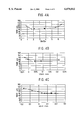
- FIG. 4A is a graph showing relationship between Ds/DH and SMD
- FIG. 4B is a graph showing relationship between 1.5 d-h and SMD
- FIG. 4C is a graph showing relationship between 4 d-H and SMD.
- FIG. 5 is a schematic view illustrating the fuel injection valve according to the first embodiment installed in an intake manifold
- FIG. 6 is a schematic side view of the injection valve shown in FIG. 5 viewed from an arrow VI;
- FIG. 7 is a schematic view illustrating disposition of a plurality of orifices of a modified orifice plate of the fuel injection valve according to the first embodiment
- FIG. 8 is a schematic view illustrating disposition of a plurality of orifices of a modified orifice plate of the fuel injection valve according to the first embodiment
- FIG. 9 is a schematic view illustrating disposition of a plurality of orifices of a modified orifice plate of the fuel injection valve according to the first embodiment
- FIG. 10 is a sectional view illustrating a portion of a nozzle of a fuel injection valve according to a second embodiment of the present invention.
- FIG. 11 is a sectional view illustrating a portion of a nozzle of a fuel injection valve according to a third embodiment of the present invention.
- FIG. 12 is a sectional view illustrating a portion of a nozzle of a fuel injection valve according to a fourth embodiment of the present invention.
- a fuel injection valve for a gasoline engine according to a first embodiment of the present invention is described with reference to FIGS. 1, 2 and 3.
- a stationary core 21 made of ferromagnetic material is accommodated in a housing mold 11 which is made of synthetic resin.
- a cylindrical movable core 22 made of magnetic material is disposed slidably in a space defined by the bottom surface of the stationary core 21, a nonmagnetic pipe 23 and a magnetic pipe 24 in line with the stationary core 21 to face each other at a certain space.
- An end of the nonmagnetic pipe 23 is fitted to an outer periphery of the lower end of the stationary core 21 and welded thereto by laser welder or the like.
- the nonmagnetic pipe 23 has an inner surface for guiding the movable core 22 and is connected to the magnetic pipe 24 at the other end thereof.
- a needle 25 is fixed to the movable core 22 at a connecting portion 25d by a laser welder or the like.
- a plurality of fuel passages are formed on the outer periphery of the connecting portion 25d.
- a valve seat 30 is inserted into the inner periphery of the magnetic pipe 24 through a spacer 28 and welded thereto by a laser welder or the like.
- the spacer 28 has a thickness to define an air gap between the stationary core 21 and the movable core 22.
- a cup-shaped orifice plate 32 made of stainless steel is welded to the bottom of the valve seat 30.
- the needle 25 has a cone-shaped edge surface 25a and an annular contact surface 25b, which is seated on a conical seat surface 31b formed on the valve seat 30.
- a sleeve 40 made of resinous material is press-fitted to the outer peripheries of the valve seat 30 and the orifice plate 32 to protect the orifice plate 32.
- the orifice plate 32 has a plurality of orifices 32a and 32b on the upper perforated surface 33 thereof, through which fuel is injected to an engine via an opening 40a of the sleeve 40.
- the movable core 22 has a spring seat 22a on the perforated surface 33 thereof, on which an end of a compression coil spring 26 is seated. The other end of the compression coil spring abutts the bottom end of an adjusting pipe 27.
- the coil spring 26 biases the movable core 22 and the needle 25 downward so that the annular contact surface 25b can be seated on the seat surface 31a of the valve seat 30.
- the adjusting pipe 27 is press-fitted into the inner periphery of the stationary core 21 and disposed to adjust the biasing force of the compression coil spring 26.
- An electro-magnetic coil 50 is wound around a spool 51 made of resinous material, which is disposed around stationary core 21, the nonmagnetic pipe 23 and the magnetic pipe 24, and the electro-magnetic coil 50 and the spool 51 are enclosed by the housing mold 11.
- a terminal 52 extends from the hosing mold 11 and is connected to the electro-magnetic coil 50 through a lead wire.
- a pair of magnetic plates 61 and 62 are disposed to surround an upper portion of the stationary core 21 and the magnetic pipe 24 to provide a path for the magnetic flux of the electro-magnetic coil 50.
- the plate also protects the electro-magnetic coil 50 from outside.
- a filter 63 is disposed at an upper portion of the stationary core 21 to remove foreign particles of the fuel supplied to the fuel injection valve 10.
- the fuel flows from the filter 63 through the inside of the adjusting pipe 27, the fuel passage formed on the connecting portion 25d of the needle 25 and a fuel passage formed on the sliding surface between the valve seat 30 and the needle 25 to the valve portion composed of the annular contact surface 25b and the valve seat surface 31b.
- the fuel chamber 35 is formed into a generally disk-like space by the perforated surface 33 of the orifice plate 32, a conical surface portion 31a of the valve seat and the edge surface 25a.
- the edge portion of the needle 25 is formed by the edge surface 25a, the annular contact surface 25b and a corner-ring portion 25c between the edge surface 25a and the annular contact surface 25b.
- the edge surface 25a is formed radially inside the contact surface 25b, and the center thereof is located on the axis of the needle.
- An axial distance h is formed between the center of the edge surface 25a and the perforated surface 33 of the orifice plate 32 when the needle 25 is lifted.
- Each of the orifices 32a and 32b has a diameter d (e.g. 0.15 mm), and the relationship between the diameter d and the axial distance h is decided by test results related to the atomization of the fuel.
- the effect of the atomization can be represented by SMD (Sauter Mean Diameter), and FIGS. 4A-4C are graphs showing relationship between the SMD and sizes of various portions of the fuel injection valve shown in FIG. 1.
- FIG. 4B shows that SMD becomes less than 100 ⁇ m and the fuel atomization can be obtained effectively if:
- the diameter d smaller than 0.25 mm such as 0.15 mm with as many orifices as possible can increase the surfaces of the fuel in contact with air, thereby increasing the atomization.
- the inside diameter of the conical surface 31a of the valve seat 30 decreases as the surface approaches the perforated surface 33 of the orifice plate 32.
- FIG. 4C shows that a distance H of the valve seat surface 31b from the perforated surface 33 is shorter than 4d, which is expressed as follows:
- the orifice plate 32 has twelve orifices 32a and 32b formed on the area of the perforated surface defining the fuel chamber 35 as shown in FIG. 2A.
- Six inner orifices 32a are disposed on an imaginary inner circle, whose diameter is DH0 as shown in FIG. 1, at equal intervals
- six outer orifices 32b are disposed on an imaginary outer circle, whose diameter is DH1 as shown in FIG. 1, at equal intervals so that each concentric circle of the inner and outer orifices 32a, 32b having the same diameter is disposed to be in contact with the concentric circles of the adjacent orifices.
- the number of inner orifices 32a and the number of the outer orifices are the same and the orifices 32a and 32b are disposed to be symmetrical with respect to a line across orifices disposed opposite sides of the perforated surface 33 of the orifice plate 32.
- the fuel can be injected evenly.
- FIG. 1 shows that the diameter Ds of the needle at the portion in contact with the valve seat, the diameter DH0 of the imaginery inner circle of the inner orifices 32a and the diameter DH1 of the imaginery outer circle of the outer orifices has the following relationship:
- Each of the inner and outer orifices 32a and 32b is inclined to direct the fuel injection outward as shown in FIG. 2B and FIG. 2C.
- the inclination angle ⁇ 1 of the inner orifices 32a and the inclination angle ⁇ 2 of the outer orifices has the following relationship:
- the fuel injected from the inner orifices and the fuel injected from the outer orifices do not intersect with each other, and the fuel can be atomized effectively.
- the fuel flows through the space between the annular contact surface 25b and the valve seat surface 31b to the orifice plate 32, where the fuel impinges on the perforated surface 33 and turns toward the fuel chamber 35, thereby forming a fuel flow along the perforated surface 33.
- the fuel flow branches out into one set of flows directly going to the orifices 32a and 32b and another set of flows passing along portions of the perforated surface 33 between the orifices 32a and 32b toward the center of the perforated surface 33, where the latter flows impinge upon one another so that the fuel are atomized effectively and returned to the orifices to be injected.
- the fuel injection valve 10 is installed in the engine intake pipe at a portion between the throttle valve (not shown) and the intake manifolds 2a, 2b and 2c as shown in FIGS. 5 and 6.
- the intake pipe shown here is one for a three-cylinder engine.
- the fuel injection valve 10 injects the fuel as indicated by broken lines.
- a variation of the orifice plate shown in FIG. 7 has four inner orifices 71 and four outer orifices 72, and another variation shown in FIG. 8 has four inner orifices 73 and eight outer orifices 74.
- Another variation shown in FIG. 9 has two inner orifices 75 and four outer orifices 76. The diameter of the orifices increases as the number thereof decreases while the above stated relationships (1), (2) and (3) are maintained.
- a fuel injection valve 10 according to a second embodiment of the present invention is described with reference to FIG. 10.
- the edge portion of a needle 80 has an edge surface 80a, an annular contact surface 80b and a corner ring surface 80c.
- the annular contact surface 80b can be seated on a valve seat surface 82a of a conical surface 82 of a valve seat 81.
- the edge surface 80a has a generally flat surface which is in parallel with an perforated surface 83c of an orifice plate 83.
- the orifice plate 83 has four orifices 84.
- the same relationships as the first embodiment exist between the axial distance h (between the edge surface and the perforated surface), the distance H of the valve seat surface from the perforated surface, and the diameter d of the orifices 84, and between the diameter of the needle Ds and the diameter of the imaginery circle DH.
- the inclination angle ⁇ of the orifices is not smaller than 15 degree in angle, preferably larger than 20 degree.
- a fuel injection valve according to a third embodiment of the present invention is described with reference to FIG. 11.
- the edge portion of a needle 86 has a spherical edge surface 86a and a contact surface 86b which is a part of the spherical surface 86a.
- the contact surface 86b can be seated on the valve seat surface 82a of a conical surface 82 of a valve seat 81.
- An orifice plate 87 has a spherical concave perforated surface 87a whose center is the same as the center of the spherical edge surface 86a, so that the perforated surface 87a of the orifice plate 87 is disposed in parallel with the edge surface 86a at an interval (axial distance) h which is discussed before.
- the perforated surface 87a has four orifices 88 having the diameter d which is discussed before.
- the same relationships as the first and embodiments exist between the interval h, the distance H of the seat surface from the perforated surface 87a, and the diameter d, and between the diameter of the needle Ds and the diameter of the imaginery circle DH (same as DH0).
- the inclination angle ⁇ of the orifices 88 is not smaller than 15 degrees in angle, preferably larger than 20 degree.
- a fuel injection valve according to a fourth embodiment is described with reference to FIG. 12.
- the edge portion of a needle 90 has a conical convex edge surface 90a and a contact surface 90b.
- the contact surface 90b can be seated on the valve seat surface 82a.
- An orifice plate 91 has a conical concave perforated surface 91a whose center axis is the same as the center axis of the edge surface 90, so that the perforated surface 87a of the orifice plate 91 is disposed in parallel with the edge surface 90a at an interval (axial distance) h which is discussed before.
- the perforated surface 91a has four orifices 92 having the diameter d which is discussed before.
- the same relationships as the first embodiment exist between the interval h, the distance H of the seat surface from the perforated surface 91a, and the diameter d, and between the diameter of the needle Ds and the diameter of the imaginery circle DH (same as DH0).
- the inclination angle ⁇ of the orifices 92 is not smaller than 15 degrees in angle.
- the fuel flows through the space between the annular contact surface 90b and the valve seat surface 82a to the perforated surface 91a, where the fuel turns toward the fuel chamber 93, thereby forming a fuel flow along the perforated surface 91a.
- the fuel flow branches out into one that flows directly going to the orifices 92 and another that flows passing along portions of the perforated surface 91a between the orifices 92 toward the center of the perforated surface 91a, where the latter flows impinge upon one another so that the fuel is atomized effectively and returned to the orifices to be injected.
- the number of orifices can be increased to any number more than 2.
Landscapes
- Engineering & Computer Science (AREA)
- Chemical & Material Sciences (AREA)
- Combustion & Propulsion (AREA)
- Mechanical Engineering (AREA)
- General Engineering & Computer Science (AREA)
- Physics & Mathematics (AREA)
- Electromagnetism (AREA)
- Fuel-Injection Apparatus (AREA)
- Nozzles (AREA)
Abstract
A fluid injection valve includes a valve seat having a conical concave surface and a valve seat surface, a needle having an edge surface and an annular contact surface whose diameter is Ds, an orifice plate having a perforated surface disposed in a downstream portion at a distance h from the edge surface of the needle and at a distance H from valve seat surface. Thus, a fluid chamber is defined by the perforated surface of the orifice plate, the edge surface of the needle and the conical concave surface of the valve seat. The perforated surface has a plurality of first orifices having a diameter d on a first circle whose diameter is DH. The fluid chamber is formed to have the following relationships among the diameters Ds, DH, d and the distances h, H: 1.5<Ds/DH<6, h<1.5 d, and H<4 d.
Description
This application is a divisional application of our prior application Ser. No. 08/942,479 filed Oct. 2, 1997, now U.S. Pat. No. 5,931,391.
The present application is based on and claims priority from Japanese Patent Applications Hei 8-283791 filed on Oct. 25, 1996, Hei 9-178161 filed on Jul. 3, 1997, and Hei 9-245091 filed on Sep. 10, 1997, the contents of which are incorporated herein by reference.
1. Field of the Invention
The present invention relates to a fluid injection valve, particularly, a fuel injection valve for an internal combustion engine.
2. Description of the Related Art
In order to reduce the fuel consumption and to control emission of the exhaust gases, atomization of the fuel is one of the most effective measures. For this purpose, there have been proposed an idea that air is blasted into the fuel and an idea that a portion of the nozzle surrounding the nozzle hole is heated.
However, if such ideas are put into practical devices, such devices would become too expensive.
U.S. Pat. No. 5,383,697 proposes an injection valve, in which a recess is provided between a perforated plate and an edge of a needle. The recess may be formed on the edge of the needle or on the perforated plate.
In the above injection valve, the fluid spreads in the axial direction when it flows into the recess and makes whirls around the recess, thereby reducing the internal energy for atomizing the fluid. Therefore, the fluid cannot be atomized effectively.
The present invention has an object of providing an improved fluid injection nozzle which can atomize the fluid effectively.
According to a main feature of the present invention, a fluid injection valve including a valve seat having a valve seat surface, a needle having an edge surface and an annular contact surface whose diameter is Ds, an orifice plate having a perforated surface disposed at a distance h from the edge surface of the needle and at a distance H from the valve seat surface, and the perforated surface has a plurality of first orifices having a diameter d on a first circle whose diameter is DH, and the diameters Ds, DH, d and the distances h, H have the following relationships: 1.5<Ds/DH<6, h<1.5 d, and H<4 d.
Another feature of the fluid injection valve as stated above is that the first orifices are disposed on the first circle at equal intervals. The diameter d may be smaller than 0.3 mm, more preferably, smaller than 0.25 mm.
Another feature of the fluid injection valve as stated above is that each of the first orifices is inclined at an angle θ1 with respect to the center axis thereof to direct fluid radially outward.
Another feature of the fluid injection valve as stated above is that the perforated surface further has a plurality of second orifices having a diameter d on a second circle outside the first circle, and the diameter of the second circle is within the same relationships as the diameter DH.
Another feature of the fluid injection valve as stated above is that the number of the second orifices is the same as the number of the first orifices, and each of the second orifices is inclined at an angle θ2 which is larger than the angle θ1 of the first orifice to direct fluid radially outward. The angle θ1 may be about 15°. However, the number of the second orifices may be twice as many as the number of the first orifices.
Another feature of the fluid injection valve as stated above is that the edge surface of the needle and the perforated surface of the orifice plate are disposed substantially in parallel with each other. The edge surface of the needle and the perforated surface of the orifice plate may be flat or curved. That is, the edge surface of the needle may be convex and the perforated surface of the orifice plate may be concave.
Another feature of the fluid injection valve as stated above is that the thickness t of the orifice plate and the diameter d of the orifices has the following relationship: 0.5<t/d<1.
Other objects, features and characteristics of the present invention as well as the functions of related parts of the present invention will become clear from a study of the following detailed description, the appended claims and the drawings. In the drawings:
FIG. 1 a sectional view illustrating an edge portion of a nozzle of a fuel injection valve according to a first embodiment of the present invention;
FIG. 2A is a schematic view illustrating disposition of a plurality of orifices of an orifice plate of the fuel injection valve according to the first embodiment, FIG. 2B is a sectional view of the orifice plate shown in FIG. 2A cut along a line B--B, and FIG. 2C is a sectional view of the orifice plate shown in FIG. 2A cut along a line C--C;
FIG. 3 is a longitudinal sectional view illustrating the fuel injection valve according to the first embodiment;
FIG. 4A is a graph showing relationship between Ds/DH and SMD, FIG. 4B is a graph showing relationship between 1.5 d-h and SMD and FIG. 4C is a graph showing relationship between 4 d-H and SMD.
FIG. 5 is a schematic view illustrating the fuel injection valve according to the first embodiment installed in an intake manifold;
FIG. 6 is a schematic side view of the injection valve shown in FIG. 5 viewed from an arrow VI;
FIG. 7 is a schematic view illustrating disposition of a plurality of orifices of a modified orifice plate of the fuel injection valve according to the first embodiment;
FIG. 8 is a schematic view illustrating disposition of a plurality of orifices of a modified orifice plate of the fuel injection valve according to the first embodiment;
FIG. 9 is a schematic view illustrating disposition of a plurality of orifices of a modified orifice plate of the fuel injection valve according to the first embodiment;
FIG. 10 is a sectional view illustrating a portion of a nozzle of a fuel injection valve according to a second embodiment of the present invention;
FIG. 11 is a sectional view illustrating a portion of a nozzle of a fuel injection valve according to a third embodiment of the present invention; and
FIG. 12 is a sectional view illustrating a portion of a nozzle of a fuel injection valve according to a fourth embodiment of the present invention.
(First Embodiment)
A fuel injection valve for a gasoline engine according to a first embodiment of the present invention is described with reference to FIGS. 1, 2 and 3.
As shown in FIG. 3, a stationary core 21 made of ferromagnetic material is accommodated in a housing mold 11 which is made of synthetic resin. A cylindrical movable core 22 made of magnetic material is disposed slidably in a space defined by the bottom surface of the stationary core 21, a nonmagnetic pipe 23 and a magnetic pipe 24 in line with the stationary core 21 to face each other at a certain space. An end of the nonmagnetic pipe 23 is fitted to an outer periphery of the lower end of the stationary core 21 and welded thereto by laser welder or the like. The nonmagnetic pipe 23 has an inner surface for guiding the movable core 22 and is connected to the magnetic pipe 24 at the other end thereof. A needle 25 is fixed to the movable core 22 at a connecting portion 25d by a laser welder or the like. A plurality of fuel passages are formed on the outer periphery of the connecting portion 25d.
A valve seat 30 is inserted into the inner periphery of the magnetic pipe 24 through a spacer 28 and welded thereto by a laser welder or the like. The spacer 28 has a thickness to define an air gap between the stationary core 21 and the movable core 22. A cup-shaped orifice plate 32 made of stainless steel is welded to the bottom of the valve seat 30. As shown in FIG. 1, the needle 25 has a cone-shaped edge surface 25a and an annular contact surface 25b, which is seated on a conical seat surface 31b formed on the valve seat 30.
A sleeve 40 made of resinous material is press-fitted to the outer peripheries of the valve seat 30 and the orifice plate 32 to protect the orifice plate 32. The orifice plate 32 has a plurality of orifices 32a and 32b on the upper perforated surface 33 thereof, through which fuel is injected to an engine via an opening 40a of the sleeve 40. The movable core 22 has a spring seat 22a on the perforated surface 33 thereof, on which an end of a compression coil spring 26 is seated. The other end of the compression coil spring abutts the bottom end of an adjusting pipe 27. Thus, the coil spring 26 biases the movable core 22 and the needle 25 downward so that the annular contact surface 25b can be seated on the seat surface 31a of the valve seat 30. The adjusting pipe 27 is press-fitted into the inner periphery of the stationary core 21 and disposed to adjust the biasing force of the compression coil spring 26.
An electro-magnetic coil 50 is wound around a spool 51 made of resinous material, which is disposed around stationary core 21, the nonmagnetic pipe 23 and the magnetic pipe 24, and the electro-magnetic coil 50 and the spool 51 are enclosed by the housing mold 11. A terminal 52 extends from the hosing mold 11 and is connected to the electro-magnetic coil 50 through a lead wire.
When the electro-magnetic coil 50 is energized by an electronic controller (not shown) through the terminal 52, the needle 25 and the movable core 22 is attracted toward the stationary core 21, and the annular contact surface 25b leaves the valve seat surface 31b against the biasing force of the compression coil spring 26.
A pair of magnetic plates 61 and 62 are disposed to surround an upper portion of the stationary core 21 and the magnetic pipe 24 to provide a path for the magnetic flux of the electro-magnetic coil 50. The plate also protects the electro-magnetic coil 50 from outside. A filter 63 is disposed at an upper portion of the stationary core 21 to remove foreign particles of the fuel supplied to the fuel injection valve 10.
The fuel flows from the filter 63 through the inside of the adjusting pipe 27, the fuel passage formed on the connecting portion 25d of the needle 25 and a fuel passage formed on the sliding surface between the valve seat 30 and the needle 25 to the valve portion composed of the annular contact surface 25b and the valve seat surface 31b.
When the annular contact surface 25b leaves the valve seat surface 31b as shown in FIG. 1, the fuel flows into a fuel chamber 35. The fuel chamber 35 is formed into a generally disk-like space by the perforated surface 33 of the orifice plate 32, a conical surface portion 31a of the valve seat and the edge surface 25a.
As shown in FIG. 1, the edge portion of the needle 25 is formed by the edge surface 25a, the annular contact surface 25b and a corner-ring portion 25c between the edge surface 25a and the annular contact surface 25b. The edge surface 25a is formed radially inside the contact surface 25b, and the center thereof is located on the axis of the needle. An axial distance h is formed between the center of the edge surface 25a and the perforated surface 33 of the orifice plate 32 when the needle 25 is lifted. Each of the orifices 32a and 32b has a diameter d (e.g. 0.15 mm), and the relationship between the diameter d and the axial distance h is decided by test results related to the atomization of the fuel. The effect of the atomization can be represented by SMD (Sauter Mean Diameter), and FIGS. 4A-4C are graphs showing relationship between the SMD and sizes of various portions of the fuel injection valve shown in FIG. 1.
FIG. 4B shows that SMD becomes less than 100 μm and the fuel atomization can be obtained effectively if:
1.5 d-h>0, where d<0.3 mm (1)
It has been found that the diameter d smaller than 0.25 mm such as 0.15 mm with as many orifices as possible can increase the surfaces of the fuel in contact with air, thereby increasing the atomization.
The inside diameter of the conical surface 31a of the valve seat 30 decreases as the surface approaches the perforated surface 33 of the orifice plate 32.
FIG. 4C shows that a distance H of the valve seat surface 31b from the perforated surface 33 is shorter than 4d, which is expressed as follows:
4 d-H>0 (2)
The orifice plate 32 has twelve orifices 32a and 32b formed on the area of the perforated surface defining the fuel chamber 35 as shown in FIG. 2A. Six inner orifices 32a are disposed on an imaginary inner circle, whose diameter is DH0 as shown in FIG. 1, at equal intervals, and six outer orifices 32b are disposed on an imaginary outer circle, whose diameter is DH1 as shown in FIG. 1, at equal intervals so that each concentric circle of the inner and outer orifices 32a, 32b having the same diameter is disposed to be in contact with the concentric circles of the adjacent orifices. The number of inner orifices 32a and the number of the outer orifices are the same and the orifices 32a and 32b are disposed to be symmetrical with respect to a line across orifices disposed opposite sides of the perforated surface 33 of the orifice plate 32.
Thus, the fuel can be injected evenly.
FIG. 1 shows that the diameter Ds of the needle at the portion in contact with the valve seat, the diameter DH0 of the imaginery inner circle of the inner orifices 32a and the diameter DH1 of the imaginery outer circle of the outer orifices has the following relationship:
1.5<Ds/DH0<6
1.5<Ds/DH1<6 (3)
Each of the inner and outer orifices 32a and 32b is inclined to direct the fuel injection outward as shown in FIG. 2B and FIG. 2C. The inclination angle θ1 of the inner orifices 32a and the inclination angle θ2 of the outer orifices has the following relationship:
θ1<θ2 (4)
Since the inclination angle of the outer orifices is larger, the fuel injected from the inner orifices and the fuel injected from the outer orifices do not intersect with each other, and the fuel can be atomized effectively.
When the electro-magnetic coil 50 is energized and the needle 25 is lifted to leave the conical surface 31a of the valve seat 30, the fuel flows through the space between the annular contact surface 25b and the valve seat surface 31b to the orifice plate 32, where the fuel impinges on the perforated surface 33 and turns toward the fuel chamber 35, thereby forming a fuel flow along the perforated surface 33. The fuel flow branches out into one set of flows directly going to the orifices 32a and 32b and another set of flows passing along portions of the perforated surface 33 between the orifices 32a and 32b toward the center of the perforated surface 33, where the latter flows impinge upon one another so that the fuel are atomized effectively and returned to the orifices to be injected.
The fuel injection valve 10 is installed in the engine intake pipe at a portion between the throttle valve (not shown) and the intake manifolds 2a, 2b and 2c as shown in FIGS. 5 and 6. The intake pipe shown here is one for a three-cylinder engine. The fuel injection valve 10 injects the fuel as indicated by broken lines.
A variation of the orifice plate shown in FIG. 7 has four inner orifices 71 and four outer orifices 72, and another variation shown in FIG. 8 has four inner orifices 73 and eight outer orifices 74. Another variation shown in FIG. 9 has two inner orifices 75 and four outer orifices 76. The diameter of the orifices increases as the number thereof decreases while the above stated relationships (1), (2) and (3) are maintained.
(Second Embodiment)
A fuel injection valve 10 according to a second embodiment of the present invention is described with reference to FIG. 10. The edge portion of a needle 80 has an edge surface 80a, an annular contact surface 80b and a corner ring surface 80c. The annular contact surface 80b can be seated on a valve seat surface 82a of a conical surface 82 of a valve seat 81. The edge surface 80a has a generally flat surface which is in parallel with an perforated surface 83c of an orifice plate 83. The orifice plate 83 has four orifices 84. In this embodiment, the same relationships as the first embodiment exist between the axial distance h (between the edge surface and the perforated surface), the distance H of the valve seat surface from the perforated surface, and the diameter d of the orifices 84, and between the diameter of the needle Ds and the diameter of the imaginery circle DH. The inclination angle θ of the orifices is not smaller than 15 degree in angle, preferably larger than 20 degree.
(Third Embodiment)
A fuel injection valve according to a third embodiment of the present invention is described with reference to FIG. 11. The edge portion of a needle 86 has a spherical edge surface 86a and a contact surface 86b which is a part of the spherical surface 86a. The contact surface 86b can be seated on the valve seat surface 82a of a conical surface 82 of a valve seat 81. An orifice plate 87 has a spherical concave perforated surface 87a whose center is the same as the center of the spherical edge surface 86a, so that the perforated surface 87a of the orifice plate 87 is disposed in parallel with the edge surface 86a at an interval (axial distance) h which is discussed before. The perforated surface 87a has four orifices 88 having the diameter d which is discussed before. In this embodiment, the same relationships as the first and embodiments exist between the interval h, the distance H of the seat surface from the perforated surface 87a, and the diameter d, and between the diameter of the needle Ds and the diameter of the imaginery circle DH (same as DH0). The inclination angle θ of the orifices 88 is not smaller than 15 degrees in angle, preferably larger than 20 degree.
When the needle is lifted from the valve seat surface 82a, fuel flows through space between annular contact surface 86b and the valve seat surface 82a to the perforated surface 87a, where the fuel turns toward the fuel chamber 89, thereby forming fuel flows along the perforated surface 87a. The fuel flow branches out into one that flows directly going to the orifices 88 and another that flows passing along portions of the perforated surface 87a between the orifices 88 toward the center of the perforated surface 87a, where the latter flows impinge upon one another so that the fuels are atomized effectively and returned to the orifices to be injected.
(Fourth Embodiment)
A fuel injection valve according to a fourth embodiment is described with reference to FIG. 12.
The edge portion of a needle 90 has a conical convex edge surface 90a and a contact surface 90b. The contact surface 90b can be seated on the valve seat surface 82a. An orifice plate 91 has a conical concave perforated surface 91a whose center axis is the same as the center axis of the edge surface 90, so that the perforated surface 87a of the orifice plate 91 is disposed in parallel with the edge surface 90a at an interval (axial distance) h which is discussed before. The perforated surface 91a has four orifices 92 having the diameter d which is discussed before.
In this embodiment, the same relationships as the first embodiment exist between the interval h, the distance H of the seat surface from the perforated surface 91a, and the diameter d, and between the diameter of the needle Ds and the diameter of the imaginery circle DH (same as DH0). The inclination angle θ of the orifices 92 is not smaller than 15 degrees in angle.
When the needle is lifted from the valve seat surface 91a, the fuel flows through the space between the annular contact surface 90b and the valve seat surface 82a to the perforated surface 91a, where the fuel turns toward the fuel chamber 93, thereby forming a fuel flow along the perforated surface 91a. The fuel flow branches out into one that flows directly going to the orifices 92 and another that flows passing along portions of the perforated surface 91a between the orifices 92 toward the center of the perforated surface 91a, where the latter flows impinge upon one another so that the fuel is atomized effectively and returned to the orifices to be injected.
The number of orifices can be increased to any number more than 2.
In the foregoing description of the present invention, the invention has been disclosed with reference to specific embodiments thereof. It will, however, be evident that various modifications and changes may be made to the specific embodiments of the present invention without departing from the broader spirit and scope of the invention as set forth in the appended claims. Accordingly, the description of the present invention in this document is to be regarded in an illustrative, rather than restrictive, sense.
Claims (42)
1. A fluid injection valve including a valve seat having a conical valve seat surface on an inner periphery thereof, a needle having an edge surface and an annular contact part for seating in annular contact with said conical valve seat surface, an orifice plate having a perforated surface disposed in a downstream portion at a distance from said edge surface of said needle and at a distance from said valve seat surface, thereby forming a fluid chamber with said perforated surface of said orifice plate, said edge surface of said needle and said inner periphery of said valve seat, wherein
said perforated surface has a plurality of first orifices on a first circle and a plurality of second orifices on a second circle outside said first circle;
said annular contact part and said valve seat surface are inclined to said perforated surface to cause fluid to impinge on said perforated surface thereby forming a fuel flow along said perforated surface to said first orifices.
2. A fluid injection valve as in claim 1, wherein
said first and second orifices are respectively disposed along said first and second circles at equal intervals.
3. A fluid injection valve as in claim 2, wherein
each of said second orifices is disposed within an angle formed between two of said first orifices.
4. A fluid injection valve as in claim 2, wherein
each of said first orifices is disposed within an angle formed between two of said second orifices.
5. A fluid injection valve as claimed in claim 1, wherein
the total number of said first and second orifices is six or more.
6. A fluid injection valve as in claim 5, wherein
each of said second orifices is disposed between two radial lines respectively extending from the center of said perforated surface across one of said first orifice.
7. A fluid injection valve as in claim 1, wherein
each of said first orifices is disposed in an angle formed between adjacent two of said second orifices.
8. A fluid injection valve as in claim 1, wherein
said edge surface has a generally flat surface which is in parallel with said perforated surface.
9. A fluid injection valve as in claim 8, wherein
said edge surface of said needle is cone-shaped.
10. A fluid injection valve as in claim 1, wherein
each of said first orifices is inclined with respect to the center axis thereof by an angle θ1, and
each of said second orifices is inclined with respect to the center axis thereof at an angle θ2 which is larger than said angle θ1.
11. A fluid injection valve as in claim 1, wherein
a diameter of a portion of said inner periphery of said valve seat adjacent said perforated surface being less than a diameter of other portions thereof, and
said first orifices are disposed radially inward from said valve seat surface.
12. A fluid injection valve as in claim 11, wherein
each of said first orifices has a diameter d, and
said perforated surface is disposed at a downstream portion of said edge surface of said needle by a distance h that is smaller than 1.5 d.
13. A fluid injection valve as in claim 12, wherein said annular contact surface has a diameter Ds,
said first circle has a diameter DH, and
there is the following relationship between said diameters Ds and DH: 1.5<Ds/DH<6.
14. A fluid injection valve as in claim 11, wherein
said second orifices are disposed radially inward from said inner periphery of said valve seat.
15. A fluid injection valve as in claim 1, wherein
each of said second orifices has a diameter d that is the same as the first orifices.
16. A fluid injection valve as in claim 15, wherein
said diameter d is less than 0.25 mm.
17. A fluid injection valve as in claim 1, wherein
said first and second orifices are disposed radially inward from said valve seat surface so that one set of fuel flows can directly flow therethrough and another set of fuel flows can flow along portions between said first and second orifices to impinge upon one another at the center of said perforated surface.
18. A fluid injection valve as in claim 17, wherein
said first and second orifices are inclined to direct said fuel flows radially outward.
19. A fluid injection valve as in claim 18, wherein
each of said first orifices is inclined with respect to the center axis thereof by an angle θ1, and
each of said second orifices is inclined with respect to the center axis thereof at an angle θ2 which is larger than said angle θ1.
20. A fluid injection valve as in claim 19, wherein
said angle θ1 is about 15°.
21. A fluid injection valve as in claim 1, wherein
said diameter d is smaller than 0.3 mm.
22. A fluid injection valve as in claim 21, wherein
each of said first orifices has a diameter d, and
said perforated surface is disposed at a downstream portion of said edge surface of said needle by a distance h that is smaller than 1.5 d.
23. A fluid injection valve as in claim 22, wherein
said perforated surface has a thickness t, and
said thickness t and said diameter d has the following relationship:
0.5<t/d/<1.
24. A fluid injection valve as in claim 23, wherein
said annular contact surface has a diameter Ds,
said first circle has a diameter DH, and
there is the following relationship between said diameters Ds and DH: 1.5<Ds/DH<6.
25. A fluid injection valve including a valve seat having a conical concave surface, a needle having an edge surface and an annular contact portion whose diameter is Ds, an orifice plate having a perforated surface disposed in a downstream portion at a distance h from said edge surface of said needle and at a distance H from said valve seat, thereby forming a fluid chamber with said perforated surface of said orifice plate, said edge surface of said needle and said conical concave surface of said valve seat, wherein
said perforated surface has a plurality of first orifices having a diameter d on a first circle whose diameter is DH, and
said annular contact portion and said valve seat are inclined to said perforated surface to open or close fluid passage to said fluid chamber and, when open, cause fluid to impinge on said perforated surface thereby forming a fuel flow along said perforated surface to said first orifices;
said diameters Ds, DH, d and said distances h, H have the following relationships:
1.5<Ds/DH<6,
h<1.5 d, and
H<4 d.
26. A fluid injection valve as in claim 25, wherein
each of said first orifices is inclined at an angle θ1 which is equal to or larger than 15°.
27. A fluid injection valve as in claim 26, wherein
said edge surface of said needle and said perforated surface of said orifice plate are substantially flat.
28. A fluid injection valve including a valve seat having a conical concave surface, a needle having an edge surface and an annular contact portion whose diameter is Ds, an orifice plate having a perforated surface disposed in a downstream portion at a distance h from said edge surface of said needle and at a distance H from said valve seat, thereby forming a fluid chamber with said perforated surface of said orifice plate, said edge surface of said needle and said conical concave surface of said valve seat, wherein
said annular contact portion and said valve seat open or close fluid passage to said fluid chamber,
said perforated surface has a plurality of first orifices having a diameter d on a first circle whose diameter is DH,
said diameters Ds, DH, d and said distances h, H have the following relationships:
1.5<Ds/DH<6,
h<1.5 d, and
H<4 d;
and said perforated surface further has a plurality of second orifices having a diameter d on a second circle outside said circle, and
the diameter of said second circle is within the same relationships as said diameter DH.
29. A fluid injection valve including a valve seat having a conical concave surface, a needle having an edge surface and an annular contact portion whose diameter is Ds, an orifice plate having a perforated surface disposed in a downstream portion at a distance h from said edge surface of said needle and at a distance H from said valve seat, thereby forming a fluid chamber with said perforated surface of said orifice plate, said edge surface of said needle and said conical concave surface of said valve seat; wherein
said annular contact portion and said valve seat open or close fluid passage to said fluid chamber,
said perforated surface has a plurality of first orifices having a diameter d on a first circle whose diameter is DH,
said diameters Ds, DH, d and said distances h, H have the following relationships:
1.5<Ds/DH<6,
h<1.5 d, and
H<4 d;
each of said first orifices is inclined at an angle θ1 with respect to the center axis thereof to direct fluid radially outward,
said edge surface of said needle and said perforated surface of said orifice plate are disposed substantially in parallel with each other,
said edge surface of said needle is convex, and
said perforated surface of said orifice plate is concave.
30. A fluid injection valve as in claim 29, wherein
said angle θ1 is equal to or larger than 15°.
31. A fluid injection valve comprising:
a reciprocatable member which seats in one position on an annular contact surface of diameter Ds to close a fluid passage; and
a perforated orifice plate disposed downstream at a distance H from the annular contact surface and at a distance h from the valve member when it is in an open position;
said perforated orifice plate having a plurality of orifices therethrough with a diameter d disposed on a circular locus of diameter DH;
said contact surface being disposed on a valve seat surface which is inclined inwardly down stream thereof but along a path which, if fully extended, intersects said orifice plate outside said plurality of orifices so as to influence fluid flows along the orifice plate inwardly toward the orifices;
wherein said dimensions Ds, DH, d, h, and H have the following relations:
1.5<Ds/DH<6,
h<1.5 d, and
h<4 d.
32. A fluid injection valve comprising:
a valve seat member having a valve seat surface on an inner periphery thereof;
a needle having an edge surface and a surface to be in contact with said valve seat surface;
an orifice plate having a perforated surface disposed in a downstream portion at a first distance from said edge surface of said needle and at a second distance from said valve seat surface, thereby forming a fluid chamber with said perforated surface of said orifice plate, said edge surface of said needle and said inner periphery of said valve seat member, said perforated surface having a plurality of first orifices on a first circle and a plurality of second orifices on a second circle outside said first circle, said plurality of first and second orifices being open to said fluid chamber.
33. A fluid injection valve as in claim 32, wherein each of said first and second orifices has a diameter d of less than 0.25 mm.
34. A fluid injection valve as in claim 33, wherein each of said first and second orifices is inclined to direct slow outwardly from the center of said perforated surface.
35. A fluid injection valve as in claim 32, wherein
said first orifices are inclined at an angle of about 15° with respect to the center axis thereof to direct fluid radially outward.
36. A fluid injection valve as in claim 35, said edge surface and said perforated surface are substantially in parallel with each other.
37. A fluid injection valve comprising:
a cylindrical valve seat member having a conical valve seat surface on an inner periphery thereof;
a needle having an edge surface and an annular contact surface of a diameter Ds; and
an orifice plate having a perforated surface disposed in a downstream portion at a first distance H from said valve seat surface and at a second distance h from said edge surface of said needle when said valve is opened, thereby forming a fluid chamber with said perforated surface of said orifice plate, said edge surface of said needle and said conical valve seat surface, said perforated surface having a plurality of first orifices of a diameter d on a first circle of a diameter DH and a plurality of second orifices on a second circle outside said first circle, wherein
said annular contact surface and said conical valve seat surface are inclined to guide fuel so that said fuel can impinge on said perforated orifice and flows along said perforated surface toward said first orifices, and
wherein said dimensions Ds, DH, d, h, and H have the following relations:
1. 5<Ds/DH<6,
h<1.5 d, and
H<4 d.
38. A fluid injection valve comprising:
a cylindrical valve seat member having a conical valve seat surface on an inner periphery thereof;
a needle having an edge surface and an annular contact surface of a diameter Ds; and
an orifice plate having a perforated surface disposed in a downstream portion at a first distance H from said valve seat surface and at a second distance h from said edge surface of said needle when said valve is opened, thereby forming a fluid chamber with said perforated surface of said orifice plate, said edge surface of said needle and said conical valve seat surface, said perforated surface having a plurality of first orifices of a diameter d on a first circle of a diameter DH, wherein
said dimensions Ds, DH, d, h, and H have the following relations:
1.5<Ds/DH<6,
h<1.5 d, and
H<4 d, and wherein
said perforated surface has a plurality of second orifices of a diameter d on a second circle of a diameter DH' outside said first circle having the following relation: 1.5<Ds/DH'<6.
39. A fluid injection valve comprising:
a cylindrical valve seat member having a conical valve seat surface on an inner periphery thereof;
a needle having a convex edge surface and an annular contact surface of a diameter Ds; and
an orifice plate having a concave perforated surface disposed in a downstream portion at a first distance H from said valve seat surface and at a second distance h from said edge surface of said needle when said valve is opened, thereby forming a fluid chamber with said perforated surface of said orifice plate, said edge surface of said needle and said conical valve seat surface, said perforated surface having a plurality of first orifices of a diameter d on a first circle of a diameter DH, wherein
said dimensions Ds, DH, d, h, and H have the following relations:
1.5<Ds/DH<6,
h<1.5 d, and
H<4 d, and wherein
each of said first orifices is inclined at an angle θ1 with respect to the center axis thereof to direct fluid radially outward, and
said convex edge surface and said concave perforated surface are substantially in parallel with each other.
40. A fluid injection valve as in claim 39, wherein said angle θ1 is about 15°.
41. A fluid injection valve comprising:
a cylindrical valve seat member having an annular valve seat of a diameter Ds;
a moving member having an edge surface to be seated on said valve seat; and
an orifice plate having a perforated surface disposed in a downstream portion at a first distance H from said valve seat and at a second distance h from said edge surface of said moving member when said valve is opened, said perforated surface having a plurality of orifices of a diameter d on a circle of a diameter DH, wherein
said annular valve seat has a conical surface extending to surround said plurality of orifices, so that said fuel can impinge on said perforated surface and flow along said perforated surface toward said first orifices, and
wherein said dimensions Ds, DH, d, h, and H have the following relations:
1.5<Ds/DH<6,
h<1.5 d, and
H<4 d.
Priority Applications (1)
| Application Number | Priority Date | Filing Date | Title |
|---|---|---|---|
| US09/335,748 US6070812A (en) | 1996-10-25 | 1999-06-18 | Fluid injection valve |
Applications Claiming Priority (8)
| Application Number | Priority Date | Filing Date | Title |
|---|---|---|---|
| JP28379196 | 1996-10-25 | ||
| JP9-178161 | 1997-07-03 | ||
| JP8-283791 | 1997-07-03 | ||
| JP17816197 | 1997-07-03 | ||
| JP9-245091 | 1997-09-10 | ||
| JP24509197A JP3750768B2 (en) | 1996-10-25 | 1997-09-10 | Fluid injection nozzle |
| US08/942,479 US5931391A (en) | 1996-10-25 | 1997-10-02 | Fluid injection valve |
| US09/335,748 US6070812A (en) | 1996-10-25 | 1999-06-18 | Fluid injection valve |
Related Parent Applications (1)
| Application Number | Title | Priority Date | Filing Date |
|---|---|---|---|
| US08/942,479 Division US5931391A (en) | 1996-10-25 | 1997-10-02 | Fluid injection valve |
Publications (1)
| Publication Number | Publication Date |
|---|---|
| US6070812A true US6070812A (en) | 2000-06-06 |
Family
ID=27324533
Family Applications (2)
| Application Number | Title | Priority Date | Filing Date |
|---|---|---|---|
| US08/942,479 Expired - Lifetime US5931391A (en) | 1996-10-25 | 1997-10-02 | Fluid injection valve |
| US09/335,748 Expired - Lifetime US6070812A (en) | 1996-10-25 | 1999-06-18 | Fluid injection valve |
Family Applications Before (1)
| Application Number | Title | Priority Date | Filing Date |
|---|---|---|---|
| US08/942,479 Expired - Lifetime US5931391A (en) | 1996-10-25 | 1997-10-02 | Fluid injection valve |
Country Status (3)
| Country | Link |
|---|---|
| US (2) | US5931391A (en) |
| JP (1) | JP3750768B2 (en) |
| DE (1) | DE19747143B4 (en) |
Cited By (28)
| Publication number | Priority date | Publication date | Assignee | Title |
|---|---|---|---|---|
| US6394367B2 (en) * | 2000-07-24 | 2002-05-28 | Mitsubishi Denki Kabushiki Kaisha | Fuel injection valve |
| US20020063174A1 (en) * | 2000-10-24 | 2002-05-30 | Akira Arioka | Fuel injection valve |
| US20020100821A1 (en) * | 2001-01-30 | 2002-08-01 | Unisia Jecs Corporation | Fuel injection valve |
| US6439484B2 (en) * | 2000-02-25 | 2002-08-27 | Denso Corporation | Fluid injection nozzle |
| US20030132320A1 (en) * | 2000-11-30 | 2003-07-17 | Thomas Sebastian | Fuel injection valve |
| US6616071B2 (en) * | 2000-10-24 | 2003-09-09 | Keihin Corporation | Fuel injection valve |
| US20030234006A1 (en) * | 2002-06-20 | 2003-12-25 | Kimitaka Saito | Fuel injection device |
| US20040164187A1 (en) * | 2003-01-22 | 2004-08-26 | Hitachi, Ltd. | Fuel injection valve |
| US20040217213A1 (en) * | 2003-01-09 | 2004-11-04 | Siemens Vdo Automotive Corporation | Spray pattern control with non-angled orifices formed on a dimpled fuel injection metering disc having a sac volume reducer |
| US20040237929A1 (en) * | 2003-05-30 | 2004-12-02 | Caterpillar Inc. | Fuel injector nozzle for an internal combustion engine |
| US20040262430A1 (en) * | 2003-06-30 | 2004-12-30 | Joseph J. Michael | Fuel injector including an orifice disc, and a method of forming the orifice disc with an asymmetrical punch |
| US20050011973A1 (en) * | 2003-07-15 | 2005-01-20 | Joseph J. Michael | Fuel injector including a compound angle orifice disc |
| US20050017098A1 (en) * | 2003-07-21 | 2005-01-27 | Joseph J. Michael | Fuel injector including an orifice disc, and a method of forming the orifice disc including punching and shaving |
| US20050242214A1 (en) * | 2004-04-30 | 2005-11-03 | Siemens Vdo Automotive, Incorporated | Fuel injector including a compound angle orifice disc for adjusting spray targeting |
| US20050241446A1 (en) * | 2004-04-28 | 2005-11-03 | Siemens Vdo Automotive, Incorporated | Asymmetrical punch |
| US20060157595A1 (en) * | 2005-01-14 | 2006-07-20 | Peterson William A Jr | Fuel injector for high fuel flow rate applications |
| US7086615B2 (en) | 2004-05-19 | 2006-08-08 | Siemens Vdo Automotive Corporation | Fuel injector including an orifice disc and a method of forming an oblique spiral fuel flow |
| US20060192036A1 (en) * | 2005-02-25 | 2006-08-31 | Joseph J M | Fuel injector including a multifaceted dimple for an orifice disc with a reduced footprint of the multifaceted dimple |
| US20070095952A1 (en) * | 2003-05-02 | 2007-05-03 | Axel Heinstein | Fuel injector |
| US20090057446A1 (en) * | 2007-08-29 | 2009-03-05 | Visteon Global Technologies, Inc. | Low pressure fuel injector nozzle |
| US20090057445A1 (en) * | 2007-08-29 | 2009-03-05 | Visteon Global Technologies, Inc. | Low pressure fuel injector nozzle |
| US20090090794A1 (en) * | 2007-10-04 | 2009-04-09 | Visteon Global Technologies, Inc. | Low pressure fuel injector |
| US20090200403A1 (en) * | 2008-02-08 | 2009-08-13 | David Ling-Shun Hung | Fuel injector |
| US20100090031A1 (en) * | 2007-01-29 | 2010-04-15 | Mitsubishi Electric Corporation | Fuel injection valve |
| EP2141350A4 (en) * | 2007-03-27 | 2011-09-21 | Mitsubishi Electric Corp | FUEL INJECTION VALVE |
| US8083160B2 (en) | 2008-03-27 | 2011-12-27 | Denso Corporation | Injector |
| US20120211691A1 (en) * | 2011-02-10 | 2012-08-23 | Robert Bosch Gmbh | Valve for Controlling a Fluid |
| US20220341382A1 (en) * | 2019-09-25 | 2022-10-27 | Bosch Corporation | Fuel injector and internal combustion engine including fuel injector |
Families Citing this family (35)
| Publication number | Priority date | Publication date | Assignee | Title |
|---|---|---|---|---|
| JPH1172067A (en) | 1997-06-24 | 1999-03-16 | Toyota Motor Corp | Fuel injection valve for internal combustion engine |
| US6095437A (en) * | 1998-01-26 | 2000-08-01 | Denso Corporation | Air-assisted type fuel injector for engines |
| JP2000145590A (en) * | 1998-11-10 | 2000-05-26 | Aisan Ind Co Ltd | Fuel injection valve |
| US6405947B2 (en) | 1999-08-10 | 2002-06-18 | Siemens Automotive Corporation | Gaseous fuel injector having low restriction seat for valve needle |
| JP2001317431A (en) * | 2000-02-25 | 2001-11-16 | Denso Corp | Fluid injection nozzle |
| JP4097056B2 (en) * | 2000-03-17 | 2008-06-04 | 株式会社デンソー | Fuel injection valve |
| US6742727B1 (en) * | 2000-05-10 | 2004-06-01 | Siemens Automotive Corporation | Injection valve with single disc turbulence generation |
| DE10049034B4 (en) * | 2000-10-04 | 2005-08-04 | Robert Bosch Gmbh | Fuel injector |
| JP3556899B2 (en) * | 2000-12-04 | 2004-08-25 | 三菱電機株式会社 | Fuel injection valve |
| DE10118164B4 (en) * | 2001-04-11 | 2007-02-08 | Robert Bosch Gmbh | Fuel injector |
| US6769625B2 (en) | 2001-06-06 | 2004-08-03 | Siemens Vdo Automotive Corporation | Spray pattern control with non-angled orifices in fuel injection metering disc |
| JP3899937B2 (en) | 2002-01-18 | 2007-03-28 | 株式会社デンソー | Fuel injection valve |
| US6966505B2 (en) * | 2002-06-28 | 2005-11-22 | Siemens Vdo Automotive Corporation | Spray control with non-angled orifices in fuel injection metering disc and methods |
| US6845930B2 (en) | 2002-06-28 | 2005-01-25 | Siemens Vdo Automotive Corp. | Spray pattern and spray distribution control with non-angled orifices in fuel injection metering disc and methods |
| US6820826B2 (en) * | 2002-09-25 | 2004-11-23 | Siemens Vdo Automotive Corp. | Spray targeting to an arcuate sector with non-angled orifices in fuel injection metering disc and method |
| US6789754B2 (en) | 2002-09-25 | 2004-09-14 | Siemens Vdo Automotive Corporation | Spray pattern control with angular orientation in fuel injector and method |
| US6929197B2 (en) * | 2002-09-25 | 2005-08-16 | Siemens Vdo Automotive Corporation | Generally circular spray pattern control with non-angled orifices in fuel injection metering disc and method |
| US7191961B2 (en) * | 2002-11-29 | 2007-03-20 | Denso Corporation | Injection hole plate and fuel injection apparatus having the same |
| DE102004005526B4 (en) | 2003-02-05 | 2022-03-31 | Denso Corporation | Fuel injector of an internal combustion engine |
| DE112004000917T5 (en) * | 2003-06-03 | 2007-10-11 | Siemens Vdo Automotive Corporation, Auburn Hills | Reduction of hydrocarbon emissions through radiation generation control by controlling fuel pressure in fuel injection systems |
| JP4025768B2 (en) * | 2004-09-27 | 2007-12-26 | 株式会社ケーヒン | Fuel injection valve |
| JP4324881B2 (en) * | 2004-10-26 | 2009-09-02 | 株式会社デンソー | Fuel injection valve |
| JP4595924B2 (en) * | 2006-02-09 | 2010-12-08 | 株式会社デンソー | Fuel injection valve |
| CN102207052B (en) * | 2006-03-29 | 2013-02-06 | 株式会社电装 | Installation structure for fuel injection valve and fuel injection system |
| JP2008121531A (en) * | 2006-11-10 | 2008-05-29 | Denso Corp | Fluid ejection device |
| JP2008248844A (en) * | 2007-03-30 | 2008-10-16 | Denso Corp | Fuel injection valve |
| JP4992801B2 (en) * | 2008-04-09 | 2012-08-08 | 株式会社デンソー | Urea water injection valve |
| JP5730024B2 (en) * | 2011-01-12 | 2015-06-03 | 三菱日立パワーシステムズ株式会社 | Spray nozzle and combustion apparatus having spray nozzle |
| DE102011007885A1 (en) * | 2011-04-21 | 2012-10-25 | Continental Automotive Gmbh | Nozzle assembly for an injection valve and injection valve |
| JP6429775B2 (en) * | 2012-08-01 | 2018-11-28 | スリーエム イノベイティブ プロパティズ カンパニー | Fuel injector with improved fuel discharge coefficient |
| DE102014204019A1 (en) | 2013-03-06 | 2014-09-11 | Denso Corporation | FUEL INJECTION VALVE |
| JP5935724B2 (en) * | 2013-03-06 | 2016-06-15 | 株式会社デンソー | Fuel injection valve |
| WO2016121475A1 (en) * | 2015-01-30 | 2016-08-04 | 日立オートモティブシステムズ株式会社 | Fuel injection valve |
| MX388935B (en) * | 2015-05-29 | 2025-03-20 | Nostrum Energy Pte Ltd | FLUID INJECTOR HOLE PLATE FOR COLLIDING FLUID JETS. |
| JP2017020394A (en) * | 2015-07-09 | 2017-01-26 | 株式会社デンソー | Fuel injection device |
Citations (13)
| Publication number | Priority date | Publication date | Assignee | Title |
|---|---|---|---|---|
| US4057190A (en) * | 1976-06-17 | 1977-11-08 | Bendix Corporation | Fuel break-up disc for injection valve |
| US4519370A (en) * | 1983-02-23 | 1985-05-28 | Toyota Jidosha Kabushiki Kaisha | Fuel injector electronically controlled engine |
| US4646974A (en) * | 1985-05-06 | 1987-03-03 | General Motors Corporation | Electromagnetic fuel injector with orifice director plate |
| US5016819A (en) * | 1989-07-20 | 1991-05-21 | Siemens-Bendix Automotive Electronics L.P. | Electromagnetic fuel injector having split stream flow director |
| JPH03264767A (en) * | 1990-03-15 | 1991-11-26 | Japan Electron Control Syst Co Ltd | fuel injector |
| US5383607A (en) * | 1991-12-19 | 1995-01-24 | Robert Bosch Gmbh | Electromagnetically actuated injection valve |
| JPH07317628A (en) * | 1994-05-20 | 1995-12-05 | Nippon Soken Inc | Fuel injection valve |
| JPH07332201A (en) * | 1994-06-03 | 1995-12-22 | Toyota Motor Corp | Fuel injection valve |
| US5484108A (en) * | 1994-03-31 | 1996-01-16 | Siemens Automotive L.P. | Fuel injector having novel multiple orifice disk members |
| JPH08277763A (en) * | 1995-04-04 | 1996-10-22 | Toyota Motor Corp | Fuel injection valve |
| US5570843A (en) * | 1994-03-16 | 1996-11-05 | Robert Bosch Gmbh | Fuel injection valve with semicircular flattenings |
| US5762272A (en) * | 1995-04-27 | 1998-06-09 | Nippondenso Co., Ltd. | Fluid injection nozzle |
| US5772124A (en) * | 1995-07-24 | 1998-06-30 | Toyota Jidosha Kabushiki Kaisha | Fuel injection valve |
-
1997
- 1997-09-10 JP JP24509197A patent/JP3750768B2/en not_active Expired - Lifetime
- 1997-10-02 US US08/942,479 patent/US5931391A/en not_active Expired - Lifetime
- 1997-10-24 DE DE19747143.9A patent/DE19747143B4/en not_active Expired - Lifetime
-
1999
- 1999-06-18 US US09/335,748 patent/US6070812A/en not_active Expired - Lifetime
Patent Citations (13)
| Publication number | Priority date | Publication date | Assignee | Title |
|---|---|---|---|---|
| US4057190A (en) * | 1976-06-17 | 1977-11-08 | Bendix Corporation | Fuel break-up disc for injection valve |
| US4519370A (en) * | 1983-02-23 | 1985-05-28 | Toyota Jidosha Kabushiki Kaisha | Fuel injector electronically controlled engine |
| US4646974A (en) * | 1985-05-06 | 1987-03-03 | General Motors Corporation | Electromagnetic fuel injector with orifice director plate |
| US5016819A (en) * | 1989-07-20 | 1991-05-21 | Siemens-Bendix Automotive Electronics L.P. | Electromagnetic fuel injector having split stream flow director |
| JPH03264767A (en) * | 1990-03-15 | 1991-11-26 | Japan Electron Control Syst Co Ltd | fuel injector |
| US5383607A (en) * | 1991-12-19 | 1995-01-24 | Robert Bosch Gmbh | Electromagnetically actuated injection valve |
| US5570843A (en) * | 1994-03-16 | 1996-11-05 | Robert Bosch Gmbh | Fuel injection valve with semicircular flattenings |
| US5484108A (en) * | 1994-03-31 | 1996-01-16 | Siemens Automotive L.P. | Fuel injector having novel multiple orifice disk members |
| JPH07317628A (en) * | 1994-05-20 | 1995-12-05 | Nippon Soken Inc | Fuel injection valve |
| JPH07332201A (en) * | 1994-06-03 | 1995-12-22 | Toyota Motor Corp | Fuel injection valve |
| JPH08277763A (en) * | 1995-04-04 | 1996-10-22 | Toyota Motor Corp | Fuel injection valve |
| US5762272A (en) * | 1995-04-27 | 1998-06-09 | Nippondenso Co., Ltd. | Fluid injection nozzle |
| US5772124A (en) * | 1995-07-24 | 1998-06-30 | Toyota Jidosha Kabushiki Kaisha | Fuel injection valve |
Non-Patent Citations (1)
| Title |
|---|
| U.S. Application of Saito et al; Appln. No. 08/749,326 filed Nov. 14, 1996. * |
Cited By (62)
| Publication number | Priority date | Publication date | Assignee | Title |
|---|---|---|---|---|
| US6439484B2 (en) * | 2000-02-25 | 2002-08-27 | Denso Corporation | Fluid injection nozzle |
| US6394367B2 (en) * | 2000-07-24 | 2002-05-28 | Mitsubishi Denki Kabushiki Kaisha | Fuel injection valve |
| US20020063174A1 (en) * | 2000-10-24 | 2002-05-30 | Akira Arioka | Fuel injection valve |
| US6616071B2 (en) * | 2000-10-24 | 2003-09-09 | Keihin Corporation | Fuel injection valve |
| US6758420B2 (en) * | 2000-10-24 | 2004-07-06 | Keihin Corporation | Fuel injection valve |
| US20030132320A1 (en) * | 2000-11-30 | 2003-07-17 | Thomas Sebastian | Fuel injection valve |
| US6764031B2 (en) * | 2000-11-30 | 2004-07-20 | Robert Bosch Gmbh | Fuel injection valve |
| US20020100821A1 (en) * | 2001-01-30 | 2002-08-01 | Unisia Jecs Corporation | Fuel injection valve |
| US6719223B2 (en) * | 2001-01-30 | 2004-04-13 | Unisia Jecs Corporation | Fuel injection valve |
| US6994279B2 (en) | 2002-06-20 | 2006-02-07 | Denso Corporation | Fuel injection device |
| US20030234006A1 (en) * | 2002-06-20 | 2003-12-25 | Kimitaka Saito | Fuel injection device |
| EP1375905A1 (en) * | 2002-06-20 | 2004-01-02 | Denso Corporation | Fuel injection device |
| US6921022B2 (en) | 2003-01-09 | 2005-07-26 | Siemens Vdo Automotive Corporation | Spray pattern control with non-angled orifices formed on dimpled fuel injection metering disc having a sac volume reducer |
| US20040217208A1 (en) * | 2003-01-09 | 2004-11-04 | Siemens Vdo Automotive Corporation | Spray pattern control with non-angled orifices formed on a generally planar metering disc and reoriented on subsequently dimpled fuel injection metering disc |
| US20040217207A1 (en) * | 2003-01-09 | 2004-11-04 | Siemens Vdo Automotive Corporation | Spray pattern control with non-angled orifices formed on dimpled fuel injection metering disc having a sac volume reducer |
| US20040217213A1 (en) * | 2003-01-09 | 2004-11-04 | Siemens Vdo Automotive Corporation | Spray pattern control with non-angled orifices formed on a dimpled fuel injection metering disc having a sac volume reducer |
| US6966499B2 (en) | 2003-01-09 | 2005-11-22 | Siemens Vdo Automotive Corporation | Spray pattern control with non-angled orifices formed on a generally planar metering disc and reoriented on subsequently dimpled fuel injection metering disc |
| US6921021B2 (en) | 2003-01-09 | 2005-07-26 | Siemens Vdo Automotive Corporation | Spray pattern control with non-angled orifices formed on a dimpled fuel injection metering disc having a sac volume reducer |
| US20040164187A1 (en) * | 2003-01-22 | 2004-08-26 | Hitachi, Ltd. | Fuel injection valve |
| US20070095952A1 (en) * | 2003-05-02 | 2007-05-03 | Axel Heinstein | Fuel injector |
| US20060231064A1 (en) * | 2003-05-30 | 2006-10-19 | Caterpillar Inc. | Fuel injector nozzle for an internal combustion engine |
| US7444980B2 (en) | 2003-05-30 | 2008-11-04 | Caterpillar Inc. | Fuel injector nozzle for an internal combustion engine |
| US20080308656A1 (en) * | 2003-05-30 | 2008-12-18 | Caterpillar Inc. | Fuel injector nozzle for an internal combustion engine |
| US7290520B2 (en) | 2003-05-30 | 2007-11-06 | Caterpillar Inc | Fuel injector nozzle for an internal combustion engine |
| US20070215099A1 (en) * | 2003-05-30 | 2007-09-20 | Caterpillar Inc. | Fuel injector nozzle for an internal combustion engine |
| US20040237929A1 (en) * | 2003-05-30 | 2004-12-02 | Caterpillar Inc. | Fuel injector nozzle for an internal combustion engine |
| US7032566B2 (en) | 2003-05-30 | 2006-04-25 | Caterpillar Inc. | Fuel injector nozzle for an internal combustion engine |
| US7909271B2 (en) | 2003-05-30 | 2011-03-22 | Caterpillar Inc. | Fuel injector nozzle for an internal combustion engine |
| US6948665B2 (en) | 2003-06-30 | 2005-09-27 | Siemens Vdo Automotive Corporation | Fuel injector including an orifice disc, and a method of forming the orifice disc with an asymmetrical punch |
| US20040262430A1 (en) * | 2003-06-30 | 2004-12-30 | Joseph J. Michael | Fuel injector including an orifice disc, and a method of forming the orifice disc with an asymmetrical punch |
| US7163159B2 (en) | 2003-07-15 | 2007-01-16 | Siemens Vdo Automotive Corporation | Fuel injector including a compound angle orifice disc |
| WO2005010344A1 (en) * | 2003-07-15 | 2005-02-03 | Siemens Vdo Automotive Corporation | Fuel injector including a compound angle orifice disc |
| US20050011973A1 (en) * | 2003-07-15 | 2005-01-20 | Joseph J. Michael | Fuel injector including a compound angle orifice disc |
| US20080029069A1 (en) * | 2003-07-21 | 2008-02-07 | Joseph J M | Fuel injector including an orifice disc, and a method of forming the orifice disc including punching and shaving |
| US7744020B2 (en) | 2003-07-21 | 2010-06-29 | Continental Automotive Systems Us, Inc. | Fuel injector including an orifice disc, and a method of forming the orifice disc including punching and shaving |
| US7444991B2 (en) | 2003-07-21 | 2008-11-04 | Continental Automotive Systems Us, Inc. | Fuel injector including an orifice disc, and a method of forming the orifice disc including punching and shaving |
| US20050017098A1 (en) * | 2003-07-21 | 2005-01-27 | Joseph J. Michael | Fuel injector including an orifice disc, and a method of forming the orifice disc including punching and shaving |
| US7159436B2 (en) | 2004-04-28 | 2007-01-09 | Siemens Vdo Automotive Corporation | Asymmetrical punch |
| US20050241446A1 (en) * | 2004-04-28 | 2005-11-03 | Siemens Vdo Automotive, Incorporated | Asymmetrical punch |
| US7481383B2 (en) * | 2004-04-30 | 2009-01-27 | Continental Automotive Systems Us, Inc. | Fuel injector including a compound angle orifice disc for adjusting spray targeting |
| US20070125889A1 (en) * | 2004-04-30 | 2007-06-07 | Joseph J M | Fuel injector including a compound angle orifice disc for adjusting spray targeting |
| US7201329B2 (en) | 2004-04-30 | 2007-04-10 | Siemens Vdo Automotive Corporation | Fuel injector including a compound angle orifice disc for adjusting spray targeting |
| US20050242214A1 (en) * | 2004-04-30 | 2005-11-03 | Siemens Vdo Automotive, Incorporated | Fuel injector including a compound angle orifice disc for adjusting spray targeting |
| US7086615B2 (en) | 2004-05-19 | 2006-08-08 | Siemens Vdo Automotive Corporation | Fuel injector including an orifice disc and a method of forming an oblique spiral fuel flow |
| US20060157595A1 (en) * | 2005-01-14 | 2006-07-20 | Peterson William A Jr | Fuel injector for high fuel flow rate applications |
| US20060192036A1 (en) * | 2005-02-25 | 2006-08-31 | Joseph J M | Fuel injector including a multifaceted dimple for an orifice disc with a reduced footprint of the multifaceted dimple |
| US20100090031A1 (en) * | 2007-01-29 | 2010-04-15 | Mitsubishi Electric Corporation | Fuel injection valve |
| US9726131B2 (en) * | 2007-01-29 | 2017-08-08 | Mitsubishi Electric Corporation | Fuel injection valve |
| EP2108811A4 (en) * | 2007-01-29 | 2013-07-03 | Mitsubishi Electric Corp | FUEL INJECTOR |
| US8302889B2 (en) | 2007-03-27 | 2012-11-06 | Mitsubishi Electric Corporation | Fuel injection valve |
| EP2141350A4 (en) * | 2007-03-27 | 2011-09-21 | Mitsubishi Electric Corp | FUEL INJECTION VALVE |
| EP2484890A3 (en) * | 2007-03-27 | 2012-10-31 | Mitsubishi Electric Corporation | Fuel injection valve |
| US7669789B2 (en) | 2007-08-29 | 2010-03-02 | Visteon Global Technologies, Inc. | Low pressure fuel injector nozzle |
| US20090057446A1 (en) * | 2007-08-29 | 2009-03-05 | Visteon Global Technologies, Inc. | Low pressure fuel injector nozzle |
| US20090057445A1 (en) * | 2007-08-29 | 2009-03-05 | Visteon Global Technologies, Inc. | Low pressure fuel injector nozzle |
| US20090090794A1 (en) * | 2007-10-04 | 2009-04-09 | Visteon Global Technologies, Inc. | Low pressure fuel injector |
| US20090200403A1 (en) * | 2008-02-08 | 2009-08-13 | David Ling-Shun Hung | Fuel injector |
| US8083160B2 (en) | 2008-03-27 | 2011-12-27 | Denso Corporation | Injector |
| US20120211691A1 (en) * | 2011-02-10 | 2012-08-23 | Robert Bosch Gmbh | Valve for Controlling a Fluid |
| US8814140B2 (en) * | 2011-02-10 | 2014-08-26 | Robert Bosch Gmbh | Valve for controlling a fluid |
| US20220341382A1 (en) * | 2019-09-25 | 2022-10-27 | Bosch Corporation | Fuel injector and internal combustion engine including fuel injector |
| US11815057B2 (en) * | 2019-09-25 | 2023-11-14 | Bosch Corporation | Fuel injector and internal combustion engine including fuel injector |
Also Published As
| Publication number | Publication date |
|---|---|
| US5931391A (en) | 1999-08-03 |
| DE19747143B4 (en) | 2014-03-13 |
| JP3750768B2 (en) | 2006-03-01 |
| DE19747143A1 (en) | 1998-04-30 |
| JPH1170347A (en) | 1999-03-16 |
Similar Documents
| Publication | Publication Date | Title |
|---|---|---|
| US6070812A (en) | Fluid injection valve | |
| US7448560B2 (en) | Unitary fluidic flow controller orifice disc for fuel injector | |
| EP1581739B1 (en) | Spray pattern control with non-angled orifices formed on dimpled fuel injection metering disc having a sac volume reducer | |
| EP1236888B1 (en) | Fluid injection nozzle | |
| KR100493602B1 (en) | Fuel injection valve | |
| US6769625B2 (en) | Spray pattern control with non-angled orifices in fuel injection metering disc | |
| US7159800B2 (en) | Spray pattern control with angular orientation in fuel injector and method | |
| US6966505B2 (en) | Spray control with non-angled orifices in fuel injection metering disc and methods | |
| US6929197B2 (en) | Generally circular spray pattern control with non-angled orifices in fuel injection metering disc and method | |
| US5772122A (en) | Fuel injection apparatus for an internal combustion engine | |
| US6845930B2 (en) | Spray pattern and spray distribution control with non-angled orifices in fuel injection metering disc and methods | |
| US20040144870A1 (en) | Fuel injection device | |
| JPH05209572A (en) | Electromagnetically operated injection valve | |
| US6983900B2 (en) | Fuel injector | |
| JP3726830B2 (en) | Fuel injection nozzle and fuel supply device | |
| JP3377004B2 (en) | Fluid injection nozzle | |
| JPH11280619A (en) | Fuel injection valve | |
| JPS59183207A (en) | Fuel injector |
Legal Events
| Date | Code | Title | Description |
|---|---|---|---|
| STCF | Information on status: patent grant |
Free format text: PATENTED CASE |
|
| FPAY | Fee payment |
Year of fee payment: 4 |
|
| FPAY | Fee payment |
Year of fee payment: 8 |
|
| FPAY | Fee payment |
Year of fee payment: 12 |