US6066907A - Brush holding device - Google Patents
Brush holding device Download PDFInfo
- Publication number
- US6066907A US6066907A US09/197,774 US19777498A US6066907A US 6066907 A US6066907 A US 6066907A US 19777498 A US19777498 A US 19777498A US 6066907 A US6066907 A US 6066907A
- Authority
- US
- United States
- Prior art keywords
- brush
- commutator
- opening
- sheet
- holding device
- Prior art date
- Legal status (The legal status is an assumption and is not a legal conclusion. Google has not performed a legal analysis and makes no representation as to the accuracy of the status listed.)
- Expired - Lifetime
Links
- 230000002093 peripheral effect Effects 0.000 claims description 16
- 239000000463 material Substances 0.000 claims description 4
- 239000004760 aramid Substances 0.000 claims description 3
- 229920003235 aromatic polyamide Polymers 0.000 claims description 3
- 239000007858 starting material Substances 0.000 abstract description 46
- 238000009413 insulation Methods 0.000 abstract description 22
- 230000004048 modification Effects 0.000 description 7
- 238000012986 modification Methods 0.000 description 7
- 244000145845 chattering Species 0.000 description 6
- 238000005299 abrasion Methods 0.000 description 5
- 239000000843 powder Substances 0.000 description 5
- 210000002105 tongue Anatomy 0.000 description 4
- XLYOFNOQVPJJNP-UHFFFAOYSA-N water Substances O XLYOFNOQVPJJNP-UHFFFAOYSA-N 0.000 description 4
- 230000000694 effects Effects 0.000 description 3
- 230000015556 catabolic process Effects 0.000 description 2
- 238000006731 degradation reaction Methods 0.000 description 2
- 230000005855 radiation Effects 0.000 description 2
- 238000004078 waterproofing Methods 0.000 description 2
- 238000009825 accumulation Methods 0.000 description 1
- 238000005336 cracking Methods 0.000 description 1
- 238000009792 diffusion process Methods 0.000 description 1
- 230000002708 enhancing effect Effects 0.000 description 1
- 239000000835 fiber Substances 0.000 description 1
- WABPQHHGFIMREM-UHFFFAOYSA-N lead(0) Chemical compound [Pb] WABPQHHGFIMREM-UHFFFAOYSA-N 0.000 description 1
- 239000002184 metal Substances 0.000 description 1
- 238000004080 punching Methods 0.000 description 1
- 238000005406 washing Methods 0.000 description 1
Images


Classifications
-
- F—MECHANICAL ENGINEERING; LIGHTING; HEATING; WEAPONS; BLASTING
- F02—COMBUSTION ENGINES; HOT-GAS OR COMBUSTION-PRODUCT ENGINE PLANTS
- F02N—STARTING OF COMBUSTION ENGINES; STARTING AIDS FOR SUCH ENGINES, NOT OTHERWISE PROVIDED FOR
- F02N11/00—Starting of engines by means of electric motors
-
- H—ELECTRICITY
- H01—ELECTRIC ELEMENTS
- H01R—ELECTRICALLY-CONDUCTIVE CONNECTIONS; STRUCTURAL ASSOCIATIONS OF A PLURALITY OF MUTUALLY-INSULATED ELECTRICAL CONNECTING ELEMENTS; COUPLING DEVICES; CURRENT COLLECTORS
- H01R39/00—Rotary current collectors, distributors or interrupters
- H01R39/02—Details for dynamo electric machines
- H01R39/38—Brush holders
-
- H—ELECTRICITY
- H02—GENERATION; CONVERSION OR DISTRIBUTION OF ELECTRIC POWER
- H02K—DYNAMO-ELECTRIC MACHINES
- H02K5/00—Casings; Enclosures; Supports
- H02K5/04—Casings or enclosures characterised by the shape, form or construction thereof
-
- H—ELECTRICITY
- H02—GENERATION; CONVERSION OR DISTRIBUTION OF ELECTRIC POWER
- H02K—DYNAMO-ELECTRIC MACHINES
- H02K5/00—Casings; Enclosures; Supports
- H02K5/04—Casings or enclosures characterised by the shape, form or construction thereof
- H02K5/10—Casings or enclosures characterised by the shape, form or construction thereof with arrangements for protection from ingress, e.g. water or fingers
-
- H—ELECTRICITY
- H02—GENERATION; CONVERSION OR DISTRIBUTION OF ELECTRIC POWER
- H02K—DYNAMO-ELECTRIC MACHINES
- H02K5/00—Casings; Enclosures; Supports
- H02K5/04—Casings or enclosures characterised by the shape, form or construction thereof
- H02K5/14—Means for supporting or protecting brushes or brush holders
- H02K5/143—Means for supporting or protecting brushes or brush holders for cooperation with commutators
- H02K5/148—Slidably supported brushes
-
- H—ELECTRICITY
- H02—GENERATION; CONVERSION OR DISTRIBUTION OF ELECTRIC POWER
- H02K—DYNAMO-ELECTRIC MACHINES
- H02K5/00—Casings; Enclosures; Supports
- H02K5/24—Casings; Enclosures; Supports specially adapted for suppression or reduction of noise or vibrations
-
- H—ELECTRICITY
- H02—GENERATION; CONVERSION OR DISTRIBUTION OF ELECTRIC POWER
- H02K—DYNAMO-ELECTRIC MACHINES
- H02K9/00—Arrangements for cooling or ventilating
Definitions
- the present invention relates to a starter having a thermal insulation cover for thermal insulation from an engine or an exhaust pipe.
- a starter has to be mounted in the engine compartment more closely to an engine block or to an engine exhaust pipe.
- the starter is therefore subjected to heat radiation from the engine and the exhaust pipe.
- resin-made parts e.g., molded cover of a magnet switch
- rubber-made parts and the like used in the starter are very likely to be damaged due to thermal softening or thermal degradation.
- Japanese Utility Model Laid-open Publication No. 61-101457 proposes to surround at least a part of the starter outer periphery with a thermal insulation cover.
- the thermal insulation cover is fixed to the starter with its engagement portions formed in a semicylindrical or hook shape by punching being engaged with a through bolt which tightly holds an end frame and a housing.
- the heat-shielding cover thus engaged with the through bolt via the engagement portions will possibly produce chattering or backlash noise sounds due to vibration and cause cracks in the thermal insulation cover due to the vibration.
- brushes movably held in respective brush holders collide with the brush holders during sliding contact with a commutator, particularly when the engine vibration is transmitted. This will cause local wear of the brushes at the colliding parts, cracks in the brushes and the like.
- the elastic member is formed in a ring shape and disposed in tight contact with the outer periphery of the frame and the inner periphery of the thermal insulation cover along the entire circumference of the frame.
- the elastic member is disposed in at least two locations spaced apart axially.
- One elastic member is disposed on the outer periphery of the abutting portion between a starter housing and a starter yoke or on a portion which is closer to the housing than the abutting portion.
- Another elastic member is disposed on the outer periphery of the abutting portion between the starter yoke and a starter end frame or on the a portion which is closer to the end frame than the yoke.
- the thermal insulation cover is formed in a cylindrical shape having a bottom which substantially covers the axial end surface of the end frame and surrounds the entirety of the rear side of the starter from the housing end side near the yoke to the end frame through the yoke.
- This thermal insulation cover shape is more advantageous than a simple cylindrical shape in enhancing the thermal insulation effect and water-proofing effect.
- a resilient sheet is disposed between a commutator and a brush holder to return a brush passing therethrough to its original position when the brush tends to move during sliding contact with the commutator.
- FIG. 1 is a side view, partly in section, of a starter according to a first embodiment of the present invention
- FIG. 2 is a sectional view showing a fitting condition of an elastic ring used in the first embodiment
- FIG. 3 is a cross sectional view of the elastic ring
- FIG. 4 is a side view, partly in section, of a starter according to a second embodiment of the present invention.
- FIG. 5 is a perspective view of an elastic member in the second embodiment
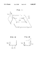
- FIG. 7 is a cross sectional view of a ring according to another modification of the embodiments.
- FIG. 8 is a partial side view, partly in cross section, of a starter according to a further modification
- FIG. 9 is a bottom view of a brush device viewed in the direction IX in FIG. 8;
- FIG. 10 is a perspective view of a sheet used for the brush device
- FIG. 11 is a perspective view of another sheet used for the brush device.
- FIG. 12 is a cross sectional view of the sheet shown in FIG. 11;
- FIG. 13 is a cross sectional view of the sheet with a brush inserted therethrough;
- FIG. 14 is a partial side view, partly in cross section, of a starter according to a still further modification
- FIG. 15 is a side view, partly in section, of a starter according to yet another variation of the first embodiment.
- a starter 1 comprises primarily a starter motor 2 for producing a rotary force, an output shaft 3 driven rotatingly by the starter motor 2, a pinion moving member (described hereunder) fitted slidably on the output shaft 3, a housing 4 surrounding the front side (left side in the figure) of the starter motor 2, an end frame 5 surrounding the rear side of the starter motor 2, and a thermal insulation cover 6 made of metal for shielding the heat from an engine and an exhaust pipe.
- the starter motor 2 is a d.c. motor, the energization of which is controlled by an external switch (not shown) in a manner well-known in the art, and includes a field magnetic device (pole core 7a and field coil 7b), a cylindrical yoke 8 supporting fixedly the field magnetic device 7 on the radially inner side thereof, an armature 9 supported rotatably in the radial inside of the field magnetic device 7, a commutator 10 disposed at one axial side of the armature 9, brushes 11 held in sliding contact with the commutator 10, and the like.
- a field magnetic device pole core 7a and field coil 7b
- a cylindrical yoke 8 supporting fixedly the field magnetic device 7 on the radially inner side thereof
- an armature 9 supported rotatably in the radial inside of the field magnetic device 7
- a commutator 10 disposed at one axial side of the armature 9, brushes 11 held in sliding contact with the commutator 10, and the like.
- the yoke 8 is sandwiched between the housing 4 and the end frame 5, which are disposed axially forward and rearward, and constitutes a frame of the starter 1 together with the housing 4 and the end frame 5.
- the pole core 7a and the field coil 7b of the field magnetic device 7 may be replaced by permanent magnets.
- the output shaft 3 is disposed coaxially with a rotary shaft 9a of the armature 9 to rotate therewith.
- a helical spline 3a is formed around the outer periphery of the output shaft 3.
- a stopper collar 12 is fitted on the front end part (leftmost end part in the figure) of the output shaft 3 to restrict forward movement of the pinion moving member.
- a snap ring 13 is fitted in a circumferential groove 3b formed around the frond end of the output shaft 3 to restrict the stopper collar 12 from moving toward the axially forward end side.
- the pinion moving member includes a pinion 15 engageable with an engine ring gear 14 to transmit the rotating force of the armature 9 (rotation of the output shaft) to the ring gear 14, and a one-way clutch 16 for transmitting the rotation of the output shaft 3 to the pinion 15.
- the pinion 15 is fitted rotatably around the outer periphery of the output shaft 3 through a bushing 17 and slidably movable along the output shaft 3 together with the bushing 17.
- a spring 18 is disposed between the pinion 15 and the stopper collar 12 to normally bias the pinion moving member rearward (in the right direction in the figure).
- the one-way clutch 16 includes a spline tube 19 enmeshed with the helical spline 3a of the output shaft 3, an outer member 20 formed integrally with the spline tube 19, an inner member 21 formed integrally with the pinion 15 and disposed radially inside the outer member 20, and rollers 22 interposed between the outer member 20 and the inner member 21.
- the one-way clutch 16 transmits the rotation of the output shaft 3 transmitted to the spline tube 19 (i.e., outer member 20) through the helical spline 3a to the inner member 21 (i.e., pinion 15) through rollers 22.
- the housing 4 has a yoke-side outer diameter which is substantially the same as that of the yoke 8
- the end frame 5 has a yoke-side outer diameter which is substantially the same as that of the yoke 8.
- the frame of the starter 1 is formed substantially in a cylindrical shape from the housing 4 near the yoke 8 to the end frame 5 near the yoke 8.
- a V-shaped groove 23 is formed circumferentially on each of the outer peripheries of fitting faces between the housing 4 and the yoke 8 and between the yoke 8 and the end frame 5.
- the thermal insulation cover 6 is provided in a cylindrical shape around the outer peripheral surface of the cylindrical frame and spaced apart radially a predetermined distance from the frame by a pair of elastic members, i.e., rubber rings 24.
- the thermal insulation cover 6 has different outer diameters between the axial end parts and the central part thereof. That is, the cover 6 has a pair of large diameter parts 6a at both axial ends thereof and a small diameter part 6b at the axially central part.
- the inner diameter of the large diameter part 6a is, however, made slightly smaller than the outer diameter of the ring 24.
- the ring 24 is shaped, as shown in FIG. 3, in a generally circular shape in cross section and has substantially the same inner diameter as the outer diameter of the cylindrical frame.
- the ring 24 is fitted in the V-shaped groove 23 formed around the frame and held in contact with the radially inner face of the large diameter part 6a of the thermal insulation cover 6.
- the ring 24 is fitted tightly in the V-shaped groove 23 and fixed between the outer peripheral surface of the frame and the inner peripheral surface of the large diameter part 6a in a compressed condition keeping resiliency.
- the thermal insulation cover 6 also has a stepped part 6c between the large-diameter part 6a and the small diameter part 6b so that the stepped part 6c contacting the ring 24 restricts the movement of the ring 24 toward the small diameter part 6b.
- the thermal insulation cover 6 is restricted in position relative to the ring 24.
- the ring 24 is pressed to the frame to fill in the V-shaped groove 23, the ring 24 is restricted from moving axially.
- the ring 24 is made of rubber and provides friction between the cover 6 and the frame, the cover 6 is held fixedly in position around the frame by the two rings 24.
- the starter 1 operates as follows.
- the armature 9 rotates and drives the output shaft 3.
- the pinion moving member advances along the output shaft 3 to engage the pinion 15 with the ring gear 14.
- the rotation of the output shaft 3 is transmitted from the pinion 15 to the ring gear 14, which in turn starts the engine.
- the thermal insulation cover 6 disposed around the cylindrical frame reflects a part of the heat radiation from the engine and the exhaust pipe. As the cover 6 is spaced away radially from the outer peripheral surface of the frame to have an air space therebetween, that is, the cover 6 is not in direct contact with the frame, it is less likely that the radiated heat received by the cover 6 is transferred to the starter frame. Thus, the starter 1 can be protected from the high temperature environment.
- the rings 24 absorb vibration to suppress the influence of the vibration transmitted to the cover 6 even when the starter 1 vibrates while receiving the vibration of the engine. Thus, generation of chattering sound noise and cracks are reduced effectively.
- the thermal insulation cover 6 is formed to surround the end frame 5 up to the rearmost side of the end frame 5.
- the elastic member used at the side of the housing 4 is the same ring 24 as in the first embodiment, while the elastic member used at the side of the end frame 5 is formed as a rubber plug 25 as shown in FIG. 5.
- the plug 25 is used at a plurality of locations (4 locations spaced apart 90 degrees from the adjacent one) along the circumference of the end frame 5.
- the plug 25 is formed with a choked part 25a around the outer periphery thereof to be attached through a hole 6d formed in the cover 6.
- the starter 1 can be protected from the high temperature environment and water splash and generation of chattering noise and cracks can be reduced as in the first embodiment.
- the V-shaped groove 23 in the first and the second embodiments need not be formed on the fitting part between the housing 4 and the yoke 8, but may be formed circumferentially around the housing 4 only so that the rubber-made ring 24 are fitted in the groove 23 as shown in FIG. 15. As far as the ring 24 is fitted in contact with or axially outside the fitting face between the housing 4 and the yoke 8, the same water-proofing effect can be provided.
- the V-shaped groove 23 and the ring 24 provided at the side of the end frame 5 in the first embodiment may be provided only on the end frame 5 as far as the fitting part between the yoke 8 and the end frame 5 is located axially inside the ring 24 as is also shown in FIG. 15.
- the rubber-made ring 24 need not be in a circular shape in cross section, but may be in a rectangular shape shown in FIG. 6 or in a triangular shape shown in FIG. 7.
- the starter 1 may be a type in which a magnet switch for controlling the electric power supply to the starter motor 2 is disposed coaxially with the rotary shaft 9a of the armature 9.
- each brush device includes a brush holder 110 holding the brush 11 movably therethrough, a spring 111 biasing the brush 11 toward the commutator 10, and a thin plate sheet 112 disposed between the commutator 10 and the brush holder 110.
- the brush holder 110 is formed in a tubular shape to surround an outer periphery of the brush 11 and hold the brush 11 movably in the longitudinal direction of the holder 110. That is, a clearance is provided between the outer periphery of the brush 11 and the inner periphery of the brush holder 110.
- the brush holder 110 has, as shown in FIG. 9, an attachment part 110a branched from the tubular brush holding part and fixed to a holder plate 113 through rivets 114.
- a cut-out 110b (FIG. 8) is formed in one side wall of the brush holder 110 so that a lead wire 115 connected to the brush 11 is taken out therethrough.
- the holder plate 113 is fixed via screws to the end frame 5 which covers the rear side of the motor 2.
- One end of a plate spring 111 is supported by an end part 110c (FIG. 9) extending from the attachment part 110a of the brush holder 110 and the other end thereof presses the end of the brush 11 to bias the brush 11 toward the commutator 10.
- the sheet 112 is made of a material including an aromatic polyamide fiber which has a high tearing strength, heat resistivity and bendability and provided in a circular ring shape to surround the outer circumferential surface of the commutator 10.
- the sheet 112 has, as shown in FIG. 10, a rectangular opening 112a for receiving the brush 11 therethrough.
- the shape of the opening 112a corresponds to the rectangular peripheral shape of the brush 11 so that the outer periphery of the brush 11 contacts the inner periphery of the sheet 112.
- a clearance which is smaller than that between the outer periphery of the brush 11 and the inner periphery of the brush holder 110 may be provided between the outer periphery of the brush 11 and the periphery of the opening 112a.
- the sheet 112 has support tongues 112b and 112c on the axial sides thereof.
- the support tongue 112b at one axial side is supported by the brush holder 110 by engaging a hole 112d formed in the tongue 112b with a hook 110d formed on the side of the brush holder 110.
- the support tongues 112c at the other axial sides are sandwiched between the attachment part 110a of the brush holder 110 and a holder plate 113, and fixed by the rivets 114 passing through circular holes 112e.
- One of the brushes 11, i.e., positive-polarity side brush 11, is insulated electrically from the rivet 114 and the holder plate 113 by an insulating plate 116 interposed between the brush holder 110 and the holder plate 113 and by an insulating bushing 117 fitted around the rivet 114.
- the brush 11 In operation, with the clearance between the brush 11 and the brush holder 110, the brush 11 is held movable within the brush holder 110 in not only the radial direction relative to the commutator 10 but also the circumferential direction, i.e., rotational direction, of the commutator 10. Therefore, in case the starter vibrates receiving vibration from the engine running at high speeds, the brush 11 responsively tends to move in the brush holder 111 in the direction of sliding on the commutator 10.
- the sheet 112 flexes in the direction of movement of the brush 11 by an amount corresponding to the movement of the brush 11 when the brush 11 moves on the commutator 10.
- the sheet 112 having resiliency tends to return to its original shape thereby to return the brush to its original position. That is, the movement of the brush 11 near the sliding contact area with the commutator 10 is restricted so that the brush 11 is restricted from colliding with the brush holder 110.
- local wear, cracking or chipping of the brush 11 which would otherwise be caused by the collision will be suppressed.
- chattering or backlash of the brush 11 within the brush holder 110 during the starter operation is suppressed as well, resulting in less chattering noise and less degradation of commutation performance.
- the sheet 112 circumferentially surrounds the sliding contact area between the commutator 10 and the brush 11, abrasion powder produced by the brush 11 during the sliding contact with the commutator 10 may be received by the sheet 112 to some extent. As a result, electrical short-circuiting which will be caused by local accumulation of the abrasion powder in the motor 2 can be avoided. Particularly, because the sheet 112 covers the sliding contact area at which the abrasion powder is produced, diffusion or scattering of the abrasion powder is suppressed. Thus, it becomes less likely that the abrasion powder adheres to the bearing part and degrades bearing performance.
- the rectangular opening 112a may be shaped smaller than the brush 11 and a cut or slit 112f may be provided at each corner of the opening 112a.
- the inner peripheral part of the sheet 112 is thus changed from the shape shown in FIG. 12 to that shown in FIG. 13 in correspondence to the peripheral shape of the brush 11 when the brush 11 is inserted into the opening 112a.
- the size of the opening 112a needs not be matched accurately to the size of the brush 11, while enabling the outer peripheral surface of the brush 11 to keep contact with the inner peripheral parts of the sheet 112.
- the commutator 10 may be so arranged that its commutating surface is perpendicular to the shaft 9a of the armature 9.
- the sheet 112 may be disposed between the commutator 10 and the brush holder 110 and the brush 11 may be received through the opening 112a.
- the sheet 12 may be made of any material as long as it is a thin resilient plate. Still further, the sheet 12 may be disposed for each brush to surround the sliding contact area and its neighboring area.
Landscapes
- Engineering & Computer Science (AREA)
- Power Engineering (AREA)
- Chemical & Material Sciences (AREA)
- Combustion & Propulsion (AREA)
- Mechanical Engineering (AREA)
- General Engineering & Computer Science (AREA)
- Motor Or Generator Frames (AREA)
Abstract
In a starter having a motor yoke, a housing and an end frame forming a cylindrical starter frame, a cylindrical thermal insulation cover is fitted around the starter frame through rubber-made elastic rings. The rings are tightly fitted in V-shaped grooves formed circumferentially on fitting faces, one being between the housing and the yoke and the other being between the yoke and the end frame. Each ring is pressed radially inward by a large diameter part of the thermal insulation cover to fill in the V-shaped groove and contact the fitting face. Further, in a motor for the starter, a resilient plate sheet is disposed between a commutator and a brush holder to return a brush passing therethrough to the original position when the brush tends to move during sliding contact with the commutator.
Description
This application is a division of application Ser. No. 08/833,800 filed Apr. 9, 1997 now U.S. Pat. No. 5,861,691 which claimed priority, as does this application, from Japanese patent applications No. 8-91444 filed Apr. 12, 1996 and No. 8-159343 filed Jun. 20, 1996, the contents of all three applications being incorporated hereinto by reference.
1. Field of the Invention
The present invention relates to a starter having a thermal insulation cover for thermal insulation from an engine or an exhaust pipe.
2. Background of the Invention
It is a recent tendency to install more auxiliary equipment than before in the engine compartment of an automotive vehicle. A starter has to be mounted in the engine compartment more closely to an engine block or to an engine exhaust pipe. The starter is therefore subjected to heat radiation from the engine and the exhaust pipe. As a result, resin-made parts (e.g., molded cover of a magnet switch), rubber-made parts and the like used in the starter are very likely to be damaged due to thermal softening or thermal degradation.
Japanese Utility Model Laid-open Publication No. 61-101457 proposes to surround at least a part of the starter outer periphery with a thermal insulation cover. The thermal insulation cover is fixed to the starter with its engagement portions formed in a semicylindrical or hook shape by punching being engaged with a through bolt which tightly holds an end frame and a housing. The heat-shielding cover thus engaged with the through bolt via the engagement portions will possibly produce chattering or backlash noise sounds due to vibration and cause cracks in the thermal insulation cover due to the vibration.
Further, brushes movably held in respective brush holders collide with the brush holders during sliding contact with a commutator, particularly when the engine vibration is transmitted. This will cause local wear of the brushes at the colliding parts, cracks in the brushes and the like.
It is therefore an object of the present invention to suppress noise and cracks caused by engine vibration in a starter having a thermal insulation cover which shields heat from an engine or exhaust pipe.
It is a further object of the present invention to suppress local wear and cracks of brushes.
According to the present invention, a thermal insulation cover is held via elastic members around a frame of a starter. The elastic members absorb vibration from the starter which vibrates with an engine and suppress the vibration which would otherwise be transmitted to the thermal insulation cover, thus reducing chattering noise and cracks caused by the vibration.
Preferably, the elastic member is formed in a ring shape and disposed in tight contact with the outer periphery of the frame and the inner periphery of the thermal insulation cover along the entire circumference of the frame. The elastic member is disposed in at least two locations spaced apart axially. One elastic member is disposed on the outer periphery of the abutting portion between a starter housing and a starter yoke or on a portion which is closer to the housing than the abutting portion. Another elastic member is disposed on the outer periphery of the abutting portion between the starter yoke and a starter end frame or on the a portion which is closer to the end frame than the yoke. Thus, each elastic member prevents water from entering into the inside of the housing through fitting faces between the housing and the yoke and between the end frame and the yoke.
Preferably, the thermal insulation cover is formed in a cylindrical shape having a bottom which substantially covers the axial end surface of the end frame and surrounds the entirety of the rear side of the starter from the housing end side near the yoke to the end frame through the yoke. This thermal insulation cover shape is more advantageous than a simple cylindrical shape in enhancing the thermal insulation effect and water-proofing effect.
Further, in a motor for the starter, a resilient sheet is disposed between a commutator and a brush holder to return a brush passing therethrough to its original position when the brush tends to move during sliding contact with the commutator.
Other objects, features and advantages of the present invention will become more apparent from the following detailed description when read with reference to the accompanying drawings, in which:
FIG. 1 is a side view, partly in section, of a starter according to a first embodiment of the present invention;
FIG. 2 is a sectional view showing a fitting condition of an elastic ring used in the first embodiment;
FIG. 3 is a cross sectional view of the elastic ring;
FIG. 4 is a side view, partly in section, of a starter according to a second embodiment of the present invention;
FIG. 5 is a perspective view of an elastic member in the second embodiment;
FIG. 6 is a cross sectional view of a ring according to a modification of the embodiments;
FIG. 7 is a cross sectional view of a ring according to another modification of the embodiments;
FIG. 8 is a partial side view, partly in cross section, of a starter according to a further modification;
FIG. 9 is a bottom view of a brush device viewed in the direction IX in FIG. 8;
FIG. 10 is a perspective view of a sheet used for the brush device;
FIG. 11 is a perspective view of another sheet used for the brush device;
FIG. 12 is a cross sectional view of the sheet shown in FIG. 11;
FIG. 13 is a cross sectional view of the sheet with a brush inserted therethrough;
FIG. 14 is a partial side view, partly in cross section, of a starter according to a still further modification;
FIG. 15 is a side view, partly in section, of a starter according to yet another variation of the first embodiment.
The present invention will be described in detail hereunder with reference to various embodiments shown in the drawings, in which the same or like parts are designated by the same reference numerals throughout the embodiments.
As shown in FIG. 1, a starter 1 comprises primarily a starter motor 2 for producing a rotary force, an output shaft 3 driven rotatingly by the starter motor 2, a pinion moving member (described hereunder) fitted slidably on the output shaft 3, a housing 4 surrounding the front side (left side in the figure) of the starter motor 2, an end frame 5 surrounding the rear side of the starter motor 2, and a thermal insulation cover 6 made of metal for shielding the heat from an engine and an exhaust pipe.
The starter motor 2 is a d.c. motor, the energization of which is controlled by an external switch (not shown) in a manner well-known in the art, and includes a field magnetic device (pole core 7a and field coil 7b), a cylindrical yoke 8 supporting fixedly the field magnetic device 7 on the radially inner side thereof, an armature 9 supported rotatably in the radial inside of the field magnetic device 7, a commutator 10 disposed at one axial side of the armature 9, brushes 11 held in sliding contact with the commutator 10, and the like. The yoke 8 is sandwiched between the housing 4 and the end frame 5, which are disposed axially forward and rearward, and constitutes a frame of the starter 1 together with the housing 4 and the end frame 5. The pole core 7a and the field coil 7b of the field magnetic device 7 may be replaced by permanent magnets.
The output shaft 3 is disposed coaxially with a rotary shaft 9a of the armature 9 to rotate therewith. A helical spline 3a is formed around the outer periphery of the output shaft 3. A stopper collar 12 is fitted on the front end part (leftmost end part in the figure) of the output shaft 3 to restrict forward movement of the pinion moving member. A snap ring 13 is fitted in a circumferential groove 3b formed around the frond end of the output shaft 3 to restrict the stopper collar 12 from moving toward the axially forward end side.
The pinion moving member includes a pinion 15 engageable with an engine ring gear 14 to transmit the rotating force of the armature 9 (rotation of the output shaft) to the ring gear 14, and a one-way clutch 16 for transmitting the rotation of the output shaft 3 to the pinion 15.
The pinion 15 is fitted rotatably around the outer periphery of the output shaft 3 through a bushing 17 and slidably movable along the output shaft 3 together with the bushing 17. A spring 18 is disposed between the pinion 15 and the stopper collar 12 to normally bias the pinion moving member rearward (in the right direction in the figure).
The one-way clutch 16 includes a spline tube 19 enmeshed with the helical spline 3a of the output shaft 3, an outer member 20 formed integrally with the spline tube 19, an inner member 21 formed integrally with the pinion 15 and disposed radially inside the outer member 20, and rollers 22 interposed between the outer member 20 and the inner member 21. The one-way clutch 16 transmits the rotation of the output shaft 3 transmitted to the spline tube 19 (i.e., outer member 20) through the helical spline 3a to the inner member 21 (i.e., pinion 15) through rollers 22.
The housing 4 has a yoke-side outer diameter which is substantially the same as that of the yoke 8, and the end frame 5 has a yoke-side outer diameter which is substantially the same as that of the yoke 8. Thus, the frame of the starter 1 is formed substantially in a cylindrical shape from the housing 4 near the yoke 8 to the end frame 5 near the yoke 8. As shown in FIG. 2, a V-shaped groove 23 is formed circumferentially on each of the outer peripheries of fitting faces between the housing 4 and the yoke 8 and between the yoke 8 and the end frame 5.
The thermal insulation cover 6 is provided in a cylindrical shape around the outer peripheral surface of the cylindrical frame and spaced apart radially a predetermined distance from the frame by a pair of elastic members, i.e., rubber rings 24. The thermal insulation cover 6 has different outer diameters between the axial end parts and the central part thereof. That is, the cover 6 has a pair of large diameter parts 6a at both axial ends thereof and a small diameter part 6b at the axially central part. The inner diameter of the large diameter part 6a is, however, made slightly smaller than the outer diameter of the ring 24.
The ring 24 is shaped, as shown in FIG. 3, in a generally circular shape in cross section and has substantially the same inner diameter as the outer diameter of the cylindrical frame. The ring 24 is fitted in the V-shaped groove 23 formed around the frame and held in contact with the radially inner face of the large diameter part 6a of the thermal insulation cover 6. As the inner diameter of the large diameter part 6a of the cover 6 is slightly smaller than the outer diameter of the ring 24, the ring 24 is fitted tightly in the V-shaped groove 23 and fixed between the outer peripheral surface of the frame and the inner peripheral surface of the large diameter part 6a in a compressed condition keeping resiliency.
The thermal insulation cover 6 also has a stepped part 6c between the large-diameter part 6a and the small diameter part 6b so that the stepped part 6c contacting the ring 24 restricts the movement of the ring 24 toward the small diameter part 6b. Thus, the thermal insulation cover 6 is restricted in position relative to the ring 24. Further, as the ring 24 is pressed to the frame to fill in the V-shaped groove 23, the ring 24 is restricted from moving axially. Still further, as the ring 24 is made of rubber and provides friction between the cover 6 and the frame, the cover 6 is held fixedly in position around the frame by the two rings 24.
The starter 1 according to this embodiment operates as follows.
When electric power is supplied to the starter motor 2 through the external switch, the armature 9 rotates and drives the output shaft 3. Through the operation of the helical spline 3a and the inertia of the one-way clutch 16, the pinion moving member advances along the output shaft 3 to engage the pinion 15 with the ring gear 14. As a result, the rotation of the output shaft 3 is transmitted from the pinion 15 to the ring gear 14, which in turn starts the engine.
According to the first embodiment, the thermal insulation cover 6 disposed around the cylindrical frame reflects a part of the heat radiation from the engine and the exhaust pipe. As the cover 6 is spaced away radially from the outer peripheral surface of the frame to have an air space therebetween, that is, the cover 6 is not in direct contact with the frame, it is less likely that the radiated heat received by the cover 6 is transferred to the starter frame. Thus, the starter 1 can be protected from the high temperature environment.
As the cover 6 is fitted around the starter frame through the rubber-made rings 24, the rings 24 absorb vibration to suppress the influence of the vibration transmitted to the cover 6 even when the starter 1 vibrates while receiving the vibration of the engine. Thus, generation of chattering sound noise and cracks are reduced effectively.
As the rubber-made rings 24 tightly cover the outer peripheries of the fitting faces between the housing 4 and the yoke 8 and between the yoke 8 and the end frame 5, water is restricted from entering the inside of the frame through the fitting faces even in case the starter 1 is subjected to the splash of water during running of a vehicle on water-covered road or car washing.
In this embodiment shown in FIG. 4, the thermal insulation cover 6 is formed to surround the end frame 5 up to the rearmost side of the end frame 5.
The elastic member used at the side of the housing 4 is the same ring 24 as in the first embodiment, while the elastic member used at the side of the end frame 5 is formed as a rubber plug 25 as shown in FIG. 5. The plug 25 is used at a plurality of locations (4 locations spaced apart 90 degrees from the adjacent one) along the circumference of the end frame 5. The plug 25 is formed with a choked part 25a around the outer periphery thereof to be attached through a hole 6d formed in the cover 6.
In this embodiment as well, the starter 1 can be protected from the high temperature environment and water splash and generation of chattering noise and cracks can be reduced as in the first embodiment.
The V-shaped groove 23 in the first and the second embodiments need not be formed on the fitting part between the housing 4 and the yoke 8, but may be formed circumferentially around the housing 4 only so that the rubber-made ring 24 are fitted in the groove 23 as shown in FIG. 15. As far as the ring 24 is fitted in contact with or axially outside the fitting face between the housing 4 and the yoke 8, the same water-proofing effect can be provided. In the same manner as above, the V-shaped groove 23 and the ring 24 provided at the side of the end frame 5 in the first embodiment may be provided only on the end frame 5 as far as the fitting part between the yoke 8 and the end frame 5 is located axially inside the ring 24 as is also shown in FIG. 15.
The rubber-made ring 24 need not be in a circular shape in cross section, but may be in a rectangular shape shown in FIG. 6 or in a triangular shape shown in FIG. 7.
The starter 1 may be a type in which a magnet switch for controlling the electric power supply to the starter motor 2 is disposed coaxially with the rotary shaft 9a of the armature 9.
In the starter motor 2 shown in FIG. 8, each brush device includes a brush holder 110 holding the brush 11 movably therethrough, a spring 111 biasing the brush 11 toward the commutator 10, and a thin plate sheet 112 disposed between the commutator 10 and the brush holder 110.
The brush holder 110 is formed in a tubular shape to surround an outer periphery of the brush 11 and hold the brush 11 movably in the longitudinal direction of the holder 110. That is, a clearance is provided between the outer periphery of the brush 11 and the inner periphery of the brush holder 110. The brush holder 110 has, as shown in FIG. 9, an attachment part 110a branched from the tubular brush holding part and fixed to a holder plate 113 through rivets 114. A cut-out 110b (FIG. 8) is formed in one side wall of the brush holder 110 so that a lead wire 115 connected to the brush 11 is taken out therethrough.
The holder plate 113 is fixed via screws to the end frame 5 which covers the rear side of the motor 2. One end of a plate spring 111 is supported by an end part 110c (FIG. 9) extending from the attachment part 110a of the brush holder 110 and the other end thereof presses the end of the brush 11 to bias the brush 11 toward the commutator 10.
The sheet 112 is made of a material including an aromatic polyamide fiber which has a high tearing strength, heat resistivity and bendability and provided in a circular ring shape to surround the outer circumferential surface of the commutator 10. The sheet 112 has, as shown in FIG. 10, a rectangular opening 112a for receiving the brush 11 therethrough. The shape of the opening 112a corresponds to the rectangular peripheral shape of the brush 11 so that the outer periphery of the brush 11 contacts the inner periphery of the sheet 112. Alternatively, a clearance which is smaller than that between the outer periphery of the brush 11 and the inner periphery of the brush holder 110 may be provided between the outer periphery of the brush 11 and the periphery of the opening 112a. Between the commutator 10 and the brush holder 110, the sheet 112 has support tongues 112b and 112c on the axial sides thereof. The support tongue 112b at one axial side is supported by the brush holder 110 by engaging a hole 112d formed in the tongue 112b with a hook 110d formed on the side of the brush holder 110. The support tongues 112c at the other axial sides are sandwiched between the attachment part 110a of the brush holder 110 and a holder plate 113, and fixed by the rivets 114 passing through circular holes 112e. One of the brushes 11, i.e., positive-polarity side brush 11, is insulated electrically from the rivet 114 and the holder plate 113 by an insulating plate 116 interposed between the brush holder 110 and the holder plate 113 and by an insulating bushing 117 fitted around the rivet 114.
In operation, with the clearance between the brush 11 and the brush holder 110, the brush 11 is held movable within the brush holder 110 in not only the radial direction relative to the commutator 10 but also the circumferential direction, i.e., rotational direction, of the commutator 10. Therefore, in case the starter vibrates receiving vibration from the engine running at high speeds, the brush 11 responsively tends to move in the brush holder 111 in the direction of sliding on the commutator 10.
Because the brush 11 is received in the opening 112a of the sheet 112 between the commutator 10 and the brush holder 110, the sheet 112 flexes in the direction of movement of the brush 11 by an amount corresponding to the movement of the brush 11 when the brush 11 moves on the commutator 10. The sheet 112 having resiliency tends to return to its original shape thereby to return the brush to its original position. That is, the movement of the brush 11 near the sliding contact area with the commutator 10 is restricted so that the brush 11 is restricted from colliding with the brush holder 110. Thus, local wear, cracking or chipping of the brush 11 which would otherwise be caused by the collision will be suppressed. Further, chattering or backlash of the brush 11 within the brush holder 110 during the starter operation is suppressed as well, resulting in less chattering noise and less degradation of commutation performance.
As the sheet 112 circumferentially surrounds the sliding contact area between the commutator 10 and the brush 11, abrasion powder produced by the brush 11 during the sliding contact with the commutator 10 may be received by the sheet 112 to some extent. As a result, electrical short-circuiting which will be caused by local accumulation of the abrasion powder in the motor 2 can be avoided. Particularly, because the sheet 112 covers the sliding contact area at which the abrasion powder is produced, diffusion or scattering of the abrasion powder is suppressed. Thus, it becomes less likely that the abrasion powder adheres to the bearing part and degrades bearing performance.
As an alternative to the sheet 112, as shown in FIG. 11, the rectangular opening 112a may be shaped smaller than the brush 11 and a cut or slit 112f may be provided at each corner of the opening 112a. The inner peripheral part of the sheet 112 is thus changed from the shape shown in FIG. 12 to that shown in FIG. 13 in correspondence to the peripheral shape of the brush 11 when the brush 11 is inserted into the opening 112a. In this case, the size of the opening 112a needs not be matched accurately to the size of the brush 11, while enabling the outer peripheral surface of the brush 11 to keep contact with the inner peripheral parts of the sheet 112.
The commutator 10 may be so arranged that its commutating surface is perpendicular to the shaft 9a of the armature 9. In this case also, the sheet 112 may be disposed between the commutator 10 and the brush holder 110 and the brush 11 may be received through the opening 112a.
Further, the sheet 12 may be made of any material as long as it is a thin resilient plate. Still further, the sheet 12 may be disposed for each brush to surround the sliding contact area and its neighboring area.
The present invention is not limited to the disclosed embodiments and modifications but may be varied in various ways without departing from the spirit and scope of the invention.
Claims (12)
1. A brush holding device for a motor having a commutator, comprising:
a brush slidably contacting the commutator;
a brush holder holding the brush therein; and
a resilient thin sheet disposed between the commutator and the brush holder, and having an opening through which the brush passes, said sheet being disposed to cover substantially an entire surface of the commutator on which the brush slides,
wherein a clearance between an inner periphery of the opening and an outer peripheral surface of the brush is smaller than a clearance between an inner peripheral surface of the brush holder and the outer peripheral surface of the brush and wherein the brush is deflected during rotation of the commutator to engage and flex the sheet in the direction in which the brush is deflected.
2. The brush holding device as in claim 1, wherein:
the opening of the sheet has an area smaller than a sectional area of the brush; and
the sheet is shaped to deform around the opening when the brush is fitted into the opening.
3. The brush holding device as in claim 1, wherein:
the sheet has the opening at a plurality of locations in correspondence with the number of brushes.
4. The brush holding device as in claim 1, wherein:
the sheet is made of an aromatic polyamide material.
5. A brush holding device for a motor having a commutator, comprising:
a brush slidably contacting the commutator;
a brush holder holding the brush therein; and
a resilient thin sheet disposed between the commutator and the brush holder, and having an opening through which the brush passes, said sheet being disposed to cover substantially an entire surface of the commutator on which the brush slides,
wherein the brush is fitted in the opening with an outer peripheral surface of the brush being in contact with an inner periphery of the opening and wherein the brush is deflected during rotation of the commutator to engage and flex the sheet in a direction in which the brush is deflected.
6. The brush holding device as in claim 5, wherein:
the opening of the sheet has an area smaller than a sectional area of the brush; and
the sheet is shaped to deform around the opening when the brush is fitted into the opening.
7. The brush holding device as in claim 5, wherein:
the sheet has the opening at a plurality of locations in correspondence with the number of brushes.
8. The brush holding device as in claim 5, wherein:
the sheet is made of an aromatic polyamide material.
9. A brush holding device for a motor having a commutator, comprising:
a resilient thin sheet disposed adjacent to a surface of the commutator to cover the surface of the commutator, and having an opening therein spaced from side edges of the sheet;
a brush positioned in the opening of the resilient thin sheet and held in slidable contact with the surface of the commutator, the opening of the resilient thin sheet having an area smaller than a sectional area of the brush and the resilient thin sheet having slits extending from the opening at a plurality of locations to deform around the opening when the brush is fitted into the opening; and
a brush holder fixed to the resilient thin sheet and holding the brush therein,
wherein the brush and the brush holder are spaced apart from each other to restrict the brush from contacting the brush holder, when the brush slides on the commutator.
10. The brush holding device as in claim 9, wherein:
the resilient thin sheet is in a generally cylindrical shape and surrounds the commutator circumferentially; and
the brush is biased in a radial direction of the commutator.
11. The brush holding device as in claim 9, wherein:
the resilient thin sheet is disposed perpendicularly to an armature shaft; and
the brush is biased in an axial direction of the armature shaft.
12. The brush holding device as in claim 9, wherein:
a clearance between an inner periphery of the opening and an outer peripheral surface of the brush is smaller than a clearance between an inner peripheral surface of the brush holder and the outer peripheral surface of the brush.
Priority Applications (1)
| Application Number | Priority Date | Filing Date | Title |
|---|---|---|---|
| US09/197,774 US6066907A (en) | 1996-04-12 | 1998-11-23 | Brush holding device |
Applications Claiming Priority (6)
| Application Number | Priority Date | Filing Date | Title |
|---|---|---|---|
| JP09144496A JP3575509B2 (en) | 1996-04-12 | 1996-04-12 | DC motor brush holding device |
| JP8-91444 | 1996-04-12 | ||
| JP8-159343 | 1996-06-20 | ||
| JP15934396A JPH109099A (en) | 1996-06-20 | 1996-06-20 | Starter |
| US08/833,800 US5861691A (en) | 1996-04-12 | 1997-04-09 | Starter with thermal insulation cover |
| US09/197,774 US6066907A (en) | 1996-04-12 | 1998-11-23 | Brush holding device |
Related Parent Applications (1)
| Application Number | Title | Priority Date | Filing Date |
|---|---|---|---|
| US08/833,800 Division US5861691A (en) | 1996-04-12 | 1997-04-09 | Starter with thermal insulation cover |
Publications (1)
| Publication Number | Publication Date |
|---|---|
| US6066907A true US6066907A (en) | 2000-05-23 |
Family
ID=26432883
Family Applications (2)
| Application Number | Title | Priority Date | Filing Date |
|---|---|---|---|
| US08/833,800 Expired - Lifetime US5861691A (en) | 1996-04-12 | 1997-04-09 | Starter with thermal insulation cover |
| US09/197,774 Expired - Lifetime US6066907A (en) | 1996-04-12 | 1998-11-23 | Brush holding device |
Family Applications Before (1)
| Application Number | Title | Priority Date | Filing Date |
|---|---|---|---|
| US08/833,800 Expired - Lifetime US5861691A (en) | 1996-04-12 | 1997-04-09 | Starter with thermal insulation cover |
Country Status (1)
| Country | Link |
|---|---|
| US (2) | US5861691A (en) |
Cited By (12)
| Publication number | Priority date | Publication date | Assignee | Title |
|---|---|---|---|---|
| US6452297B2 (en) * | 2000-03-22 | 2002-09-17 | Asmo Co., Ltd. | Motor device having commutator and brush outside yoke |
| US20020180301A1 (en) * | 2001-05-29 | 2002-12-05 | Yoshio Ebihara | Electric motor contact member protector |
| US20030071524A1 (en) * | 2001-10-16 | 2003-04-17 | Mitsubishi Denki Kabushiki Kaisha | Electrical actuator |
| WO2004088823A2 (en) | 2003-04-04 | 2004-10-14 | Wittenstein Ag | Electric motor and/ or transmission |
| US20060267446A1 (en) * | 2005-05-30 | 2006-11-30 | Denso Corporation | Automotive engine starter and electric rotary machine designed to withstand vibrational impact |
| US20080084124A1 (en) * | 2006-10-06 | 2008-04-10 | Wojciech Golab | Dynamoelectric machine brush holder assembly and method |
| US20080084133A1 (en) * | 2006-10-06 | 2008-04-10 | Steven Burton | Dynamoelectric machine brush and method |
| US20080083556A1 (en) * | 2006-10-06 | 2008-04-10 | Gustavo Sumcad | Dynamoelectric machine grommet |
| US20080084132A1 (en) * | 2006-10-06 | 2008-04-10 | Wojciech Golab | Dynamoelectric machine conductor and method |
| US20080174117A1 (en) * | 2006-11-24 | 2008-07-24 | Denso Corporation | DC motor having enhanced startability |
| WO2011039278A1 (en) * | 2009-10-02 | 2011-04-07 | Robert Bosch Gmbh | Starter device comprising a relay |
| US20120186869A1 (en) * | 2011-01-21 | 2012-07-26 | Remy Technologies, L.L.C. | Method of blocking electro-magnetic interference (emi) in an electric machine and apparatus |
Families Citing this family (19)
| Publication number | Priority date | Publication date | Assignee | Title |
|---|---|---|---|---|
| US6262504B1 (en) | 1999-02-10 | 2001-07-17 | Siemens Canada Limited | HVAC motor and cover structure |
| US6281607B1 (en) * | 1999-04-06 | 2001-08-28 | Trw Inc. | Electric motor with vibration attenuation |
| FR2802725B1 (en) * | 1999-12-20 | 2008-06-27 | Denso Corp | ROTARY ELECTRIC MACHINE HAVING AN ELASTIC ARMOR SUPPORT STRUCTURE |
| FR2817405B1 (en) * | 2000-11-24 | 2004-09-10 | Leroy Somer Moteurs | ROTATING MACHINE STATOR |
| JP2002180938A (en) * | 2000-12-08 | 2002-06-26 | Denso Corp | Starter |
| DE10065124A1 (en) * | 2000-12-28 | 2002-07-04 | Bosch Gmbh Robert | Device for releasably connecting a wiper blade to a wiper arm |
| DE10131590A1 (en) * | 2001-07-03 | 2003-01-16 | Bosch Gmbh Robert | Device for fastening an electric motor |
| US6809445B2 (en) * | 2002-04-04 | 2004-10-26 | General Electric Company | Method and apparatus for electric motor lead wire retention |
| US7405207B2 (en) * | 2002-06-17 | 2008-07-29 | Epigenesis Pharmaceuticals, Inc. | Nebulizer formulations of dehydroepiandrosterone and methods of treating asthma or chronic obstructive pulmonary disease using compositions thereof |
| DE10326996A1 (en) * | 2003-06-12 | 2005-01-05 | Robert Bosch Gmbh | Decoupling device for electric motors and method for producing an electric motor |
| JP2005184921A (en) * | 2003-12-17 | 2005-07-07 | Denso Corp | Motor housing |
| DE112005000322T5 (en) * | 2004-02-09 | 2006-12-21 | Shinano Kenshi K.K., Ueda | Motor driving device |
| US7550881B1 (en) * | 2006-01-17 | 2009-06-23 | Honeywell International Inc. | Vibration damper for generator or motor stator |
| DE102011076532A1 (en) * | 2011-05-26 | 2012-11-29 | Zf Friedrichshafen Ag | Electrodynamic machine with an additional jacket |
| CN103006104A (en) * | 2011-09-26 | 2013-04-03 | 德昌电机(深圳)有限公司 | Food treating machine, motor assembly and bread machine |
| JP6212283B2 (en) * | 2013-05-23 | 2017-10-11 | マブチモーター株式会社 | Method for manufacturing motor and movement regulating structure |
| RU2705619C2 (en) * | 2014-06-17 | 2019-11-11 | Конинклейке Филипс Н.В. | Drive system for individual care device and method for operation thereof |
| FR3051848A1 (en) * | 2016-05-27 | 2017-12-01 | Valeo Equip Electr Moteur | VEHICLE ENGINE STARTER WITH REINFORCED SEALING |
| US11085394B2 (en) * | 2018-03-30 | 2021-08-10 | Honda Motor Co., Ltd. | Engine |
Citations (17)
| Publication number | Priority date | Publication date | Assignee | Title |
|---|---|---|---|---|
| US4117359A (en) * | 1974-01-30 | 1978-09-26 | Teldix Gmbh | Bearing and drive structure for spinning turbine |
| US4499390A (en) * | 1982-11-30 | 1985-02-12 | Mitsubishi Denki Kabushiki Kaisha | Waterproof structure for slip rings of an a.c. generator for a car |
| JPS61101457A (en) * | 1984-10-24 | 1986-05-20 | 株式会社日立製作所 | Ceramic insulating substrate material |
| US4626724A (en) * | 1984-05-17 | 1986-12-02 | Mitsubishi Denki Kabushiki Kaisha | Waterproof device for electric motor |
| US4626720A (en) * | 1981-03-06 | 1986-12-02 | Hitachi, Ltd. | Cooling apparatus for motor means to protect commutator from dust and moisture in cooling air |
| US4737673A (en) * | 1986-09-19 | 1988-04-12 | Papst Motoren Gmbh & Co. Kg | Bearing assembly for an axially compact miniature motor or ventilator |
| US4945270A (en) * | 1987-02-13 | 1990-07-31 | Mitsubishi Denki Kabushiki Kaisha | Moisture drain structure for a dynamoelectric machine and manufacturing method therefor |
| US5023466A (en) * | 1988-02-12 | 1991-06-11 | Mitsubishi Denki Kabushiki Kaisha | Coaxial starter |
| US5233248A (en) * | 1991-07-10 | 1993-08-03 | Mitsubishi Denki Kabushiki Kaisha | Heat resistant and explosion-proof type permanent magnetic synchronous motor |
| US5235227A (en) * | 1991-01-23 | 1993-08-10 | Panavision International L.P. | Noise and vibration dampened electric motor such as for use with a sound movie camera |
| US5296772A (en) * | 1993-04-05 | 1994-03-22 | General Motors Corporation | Ventilated brush holder |
| US5334897A (en) * | 1993-05-24 | 1994-08-02 | North American Philips Corporation | Electric motor with encased housing |
| US5345132A (en) * | 1992-06-23 | 1994-09-06 | Hitachi Automotive Engineering | Vehicular alternating current dynamo |
| US5402027A (en) * | 1992-12-22 | 1995-03-28 | Johnson Electric S.A. | Brush assembly for an electric motor |
| US5530304A (en) * | 1993-01-20 | 1996-06-25 | Hitachi, Ltd. | Miniature motor and fan using the same |
| US5616973A (en) * | 1994-06-29 | 1997-04-01 | Yeomans Chicago Corporation | Pump motor housing with improved cooling means |
| US5753992A (en) * | 1996-11-07 | 1998-05-19 | Delco Remy America Inc | Single piece brush fixture for dynamoelectric machine |
-
1997
- 1997-04-09 US US08/833,800 patent/US5861691A/en not_active Expired - Lifetime
-
1998
- 1998-11-23 US US09/197,774 patent/US6066907A/en not_active Expired - Lifetime
Patent Citations (17)
| Publication number | Priority date | Publication date | Assignee | Title |
|---|---|---|---|---|
| US4117359A (en) * | 1974-01-30 | 1978-09-26 | Teldix Gmbh | Bearing and drive structure for spinning turbine |
| US4626720A (en) * | 1981-03-06 | 1986-12-02 | Hitachi, Ltd. | Cooling apparatus for motor means to protect commutator from dust and moisture in cooling air |
| US4499390A (en) * | 1982-11-30 | 1985-02-12 | Mitsubishi Denki Kabushiki Kaisha | Waterproof structure for slip rings of an a.c. generator for a car |
| US4626724A (en) * | 1984-05-17 | 1986-12-02 | Mitsubishi Denki Kabushiki Kaisha | Waterproof device for electric motor |
| JPS61101457A (en) * | 1984-10-24 | 1986-05-20 | 株式会社日立製作所 | Ceramic insulating substrate material |
| US4737673A (en) * | 1986-09-19 | 1988-04-12 | Papst Motoren Gmbh & Co. Kg | Bearing assembly for an axially compact miniature motor or ventilator |
| US4945270A (en) * | 1987-02-13 | 1990-07-31 | Mitsubishi Denki Kabushiki Kaisha | Moisture drain structure for a dynamoelectric machine and manufacturing method therefor |
| US5023466A (en) * | 1988-02-12 | 1991-06-11 | Mitsubishi Denki Kabushiki Kaisha | Coaxial starter |
| US5235227A (en) * | 1991-01-23 | 1993-08-10 | Panavision International L.P. | Noise and vibration dampened electric motor such as for use with a sound movie camera |
| US5233248A (en) * | 1991-07-10 | 1993-08-03 | Mitsubishi Denki Kabushiki Kaisha | Heat resistant and explosion-proof type permanent magnetic synchronous motor |
| US5345132A (en) * | 1992-06-23 | 1994-09-06 | Hitachi Automotive Engineering | Vehicular alternating current dynamo |
| US5402027A (en) * | 1992-12-22 | 1995-03-28 | Johnson Electric S.A. | Brush assembly for an electric motor |
| US5530304A (en) * | 1993-01-20 | 1996-06-25 | Hitachi, Ltd. | Miniature motor and fan using the same |
| US5296772A (en) * | 1993-04-05 | 1994-03-22 | General Motors Corporation | Ventilated brush holder |
| US5334897A (en) * | 1993-05-24 | 1994-08-02 | North American Philips Corporation | Electric motor with encased housing |
| US5616973A (en) * | 1994-06-29 | 1997-04-01 | Yeomans Chicago Corporation | Pump motor housing with improved cooling means |
| US5753992A (en) * | 1996-11-07 | 1998-05-19 | Delco Remy America Inc | Single piece brush fixture for dynamoelectric machine |
Cited By (26)
| Publication number | Priority date | Publication date | Assignee | Title |
|---|---|---|---|---|
| US6452297B2 (en) * | 2000-03-22 | 2002-09-17 | Asmo Co., Ltd. | Motor device having commutator and brush outside yoke |
| US20020180301A1 (en) * | 2001-05-29 | 2002-12-05 | Yoshio Ebihara | Electric motor contact member protector |
| US6800982B2 (en) * | 2001-05-29 | 2004-10-05 | Denso Corporation | Electric motor having brush holder with axial movement limiting armature contact member protector |
| US7053510B2 (en) * | 2001-10-16 | 2006-05-30 | Mitsubishi Denki Kabushiki Kaisha | Electrical actuator |
| US20030071524A1 (en) * | 2001-10-16 | 2003-04-17 | Mitsubishi Denki Kabushiki Kaisha | Electrical actuator |
| US7694576B2 (en) | 2003-04-04 | 2010-04-13 | Wittenstein Ag | Electric motor and/or transmission |
| WO2004088823A2 (en) | 2003-04-04 | 2004-10-14 | Wittenstein Ag | Electric motor and/ or transmission |
| US20060207338A1 (en) * | 2003-04-04 | 2006-09-21 | Frank Michel | Electric motor and/or transmission |
| WO2004088823A3 (en) * | 2003-04-04 | 2004-12-02 | Wittenstein Ag | Electric motor and/ or transmission |
| US7893593B2 (en) * | 2005-05-30 | 2011-02-22 | Denso Corporation | Automotive engine starter and electric rotary machine designed to withstand vibrational impact |
| US20100001614A1 (en) * | 2005-05-30 | 2010-01-07 | Denso Corporation | Automotive engine starter and electric rotary machine designed to withstand vibrational impact |
| US20060267446A1 (en) * | 2005-05-30 | 2006-11-30 | Denso Corporation | Automotive engine starter and electric rotary machine designed to withstand vibrational impact |
| US7847467B2 (en) * | 2005-05-30 | 2010-12-07 | Denso Corporation | Automotive engine starter and electric rotary machine designed to withstand vibrational impact |
| US20100001613A1 (en) * | 2005-05-30 | 2010-01-07 | Denso Corporation | Automotive engine starter and electric rotary machine designed to withstand vibrational impact |
| US7608956B2 (en) * | 2005-05-30 | 2009-10-27 | Denso Corporation | Automotive engine starter and electric rotary machine designed to withstand vibrational impact |
| US20080084124A1 (en) * | 2006-10-06 | 2008-04-10 | Wojciech Golab | Dynamoelectric machine brush holder assembly and method |
| US7696666B2 (en) | 2006-10-06 | 2010-04-13 | Remy Technologies, L.L.C. | Dynamoelectric machine grommet |
| US20080084133A1 (en) * | 2006-10-06 | 2008-04-10 | Steven Burton | Dynamoelectric machine brush and method |
| US7705512B2 (en) | 2006-10-06 | 2010-04-27 | Remy International, Inc. | Dynamoelectric machine conductor |
| US20080084132A1 (en) * | 2006-10-06 | 2008-04-10 | Wojciech Golab | Dynamoelectric machine conductor and method |
| US20080083556A1 (en) * | 2006-10-06 | 2008-04-10 | Gustavo Sumcad | Dynamoelectric machine grommet |
| US20080174117A1 (en) * | 2006-11-24 | 2008-07-24 | Denso Corporation | DC motor having enhanced startability |
| US7990017B2 (en) * | 2006-11-24 | 2011-08-02 | Denso Corporation | DC motor having enhanced startability |
| WO2011039278A1 (en) * | 2009-10-02 | 2011-04-07 | Robert Bosch Gmbh | Starter device comprising a relay |
| US20120186869A1 (en) * | 2011-01-21 | 2012-07-26 | Remy Technologies, L.L.C. | Method of blocking electro-magnetic interference (emi) in an electric machine and apparatus |
| US8513541B2 (en) * | 2011-01-21 | 2013-08-20 | Remy Technologies, L.L.C. | Method of blocking electro-magnetic interference (EMI) in an electric machine and apparatus |
Also Published As
| Publication number | Publication date |
|---|---|
| US5861691A (en) | 1999-01-19 |
Similar Documents
| Publication | Publication Date | Title |
|---|---|---|
| US6066907A (en) | Brush holding device | |
| US5345132A (en) | Vehicular alternating current dynamo | |
| US6326716B1 (en) | Brush holder arrangement of DC motor | |
| US8803390B2 (en) | Dynamo-electric machine | |
| JP4996696B2 (en) | Device for holding an electric machine with vibration isolation | |
| US5551546A (en) | Electromagnetic clutch | |
| US5414317A (en) | Electric motor with brush card isolated from endframe | |
| CA1318715C (en) | Dc motor with a durable pigtail arrangement | |
| US4990874A (en) | Core and contact assembly for a coaxial engine starter | |
| US6876111B2 (en) | Bearing structure having a resin case with axial slit | |
| US5200658A (en) | Electric motor with through-bolt guides for mounting | |
| US5895995A (en) | Starter having an improved brush holder | |
| AU3145800A (en) | Electric motor | |
| JPH09133067A (en) | Starter with reduction gear mechanism | |
| US6787963B2 (en) | Brush assembly | |
| US3143677A (en) | Brush holder assembly | |
| KR19980063824A (en) | Starter motor | |
| JP4094876B2 (en) | Motor brush holder fixing structure | |
| JPH109099A (en) | Starter | |
| JP3575509B2 (en) | DC motor brush holding device | |
| US5065038A (en) | Coaxial engine starter | |
| JP2003189551A (en) | Dynamo-electric machine | |
| JP3764094B2 (en) | motor | |
| WO2020121559A1 (en) | Fan motor | |
| KR19980010647U (en) | Car motor |
Legal Events
| Date | Code | Title | Description |
|---|---|---|---|
| AS | Assignment |
Owner name: DENSO CORPORATION, JAPAN Free format text: ASSIGNMENT OF ASSIGNORS INTEREST;ASSIGNORS:MATSUSHIMA, KEIICHI;NIIMI, MASAMI;REEL/FRAME:009632/0455;SIGNING DATES FROM 19981026 TO 19981102 |
|
| STCF | Information on status: patent grant |
Free format text: PATENTED CASE |
|
| FEPP | Fee payment procedure |
Free format text: PAYOR NUMBER ASSIGNED (ORIGINAL EVENT CODE: ASPN); ENTITY STATUS OF PATENT OWNER: LARGE ENTITY |
|
| FPAY | Fee payment |
Year of fee payment: 4 |
|
| FPAY | Fee payment |
Year of fee payment: 8 |
|
| FPAY | Fee payment |
Year of fee payment: 12 |