US6065804A - Removable folding seat - Google Patents
Removable folding seat Download PDFInfo
- Publication number
- US6065804A US6065804A US09/168,172 US16817298A US6065804A US 6065804 A US6065804 A US 6065804A US 16817298 A US16817298 A US 16817298A US 6065804 A US6065804 A US 6065804A
- Authority
- US
- United States
- Prior art keywords
- seat
- locking member
- lever
- set forth
- locking
- Prior art date
- Legal status (The legal status is an assumption and is not a legal conclusion. Google has not performed a legal analysis and makes no representation as to the accuracy of the status listed.)
- Expired - Lifetime
Links
Images


Classifications
-
- B—PERFORMING OPERATIONS; TRANSPORTING
- B60—VEHICLES IN GENERAL
- B60N—SEATS SPECIALLY ADAPTED FOR VEHICLES; VEHICLE PASSENGER ACCOMMODATION NOT OTHERWISE PROVIDED FOR
- B60N2/00—Seats specially adapted for vehicles; Arrangement or mounting of seats in vehicles
- B60N2/24—Seats specially adapted for vehicles; Arrangement or mounting of seats in vehicles for particular purposes or particular vehicles
- B60N2/30—Non-dismountable or dismountable seats storable in a non-use position, e.g. foldable spare seats
- B60N2/3097—Dismountable seats storable in a non-use position
-
- B—PERFORMING OPERATIONS; TRANSPORTING
- B60—VEHICLES IN GENERAL
- B60N—SEATS SPECIALLY ADAPTED FOR VEHICLES; VEHICLE PASSENGER ACCOMMODATION NOT OTHERWISE PROVIDED FOR
- B60N2/00—Seats specially adapted for vehicles; Arrangement or mounting of seats in vehicles
- B60N2/005—Arrangement or mounting of seats in vehicles, e.g. dismountable auxiliary seats
- B60N2/015—Attaching seats directly to vehicle chassis
- B60N2/01508—Attaching seats directly to vehicle chassis using quick release attachments
- B60N2/01516—Attaching seats directly to vehicle chassis using quick release attachments with locking mechanisms
- B60N2/01583—Attaching seats directly to vehicle chassis using quick release attachments with locking mechanisms locking on transversal elements on the vehicle floor or rail, e.g. transversal rods
-
- B—PERFORMING OPERATIONS; TRANSPORTING
- B60—VEHICLES IN GENERAL
- B60N—SEATS SPECIALLY ADAPTED FOR VEHICLES; VEHICLE PASSENGER ACCOMMODATION NOT OTHERWISE PROVIDED FOR
- B60N2/00—Seats specially adapted for vehicles; Arrangement or mounting of seats in vehicles
- B60N2/24—Seats specially adapted for vehicles; Arrangement or mounting of seats in vehicles for particular purposes or particular vehicles
- B60N2/30—Non-dismountable or dismountable seats storable in a non-use position, e.g. foldable spare seats
- B60N2/3002—Non-dismountable or dismountable seats storable in a non-use position, e.g. foldable spare seats back-rest movements
- B60N2/3004—Non-dismountable or dismountable seats storable in a non-use position, e.g. foldable spare seats back-rest movements by rotation only
- B60N2/3009—Non-dismountable or dismountable seats storable in a non-use position, e.g. foldable spare seats back-rest movements by rotation only about transversal axis
- B60N2/3011—Non-dismountable or dismountable seats storable in a non-use position, e.g. foldable spare seats back-rest movements by rotation only about transversal axis the back-rest being hinged on the cushion, e.g. "portefeuille movement"
-
- B—PERFORMING OPERATIONS; TRANSPORTING
- B60—VEHICLES IN GENERAL
- B60N—SEATS SPECIALLY ADAPTED FOR VEHICLES; VEHICLE PASSENGER ACCOMMODATION NOT OTHERWISE PROVIDED FOR
- B60N2/00—Seats specially adapted for vehicles; Arrangement or mounting of seats in vehicles
- B60N2/24—Seats specially adapted for vehicles; Arrangement or mounting of seats in vehicles for particular purposes or particular vehicles
- B60N2/30—Non-dismountable or dismountable seats storable in a non-use position, e.g. foldable spare seats
- B60N2/3038—Cushion movements
- B60N2/304—Cushion movements by rotation only
- B60N2/3045—Cushion movements by rotation only about transversal axis
- B60N2/305—Cushion movements by rotation only about transversal axis the cushion being hinged on the vehicle frame
-
- B—PERFORMING OPERATIONS; TRANSPORTING
- B60—VEHICLES IN GENERAL
- B60N—SEATS SPECIALLY ADAPTED FOR VEHICLES; VEHICLE PASSENGER ACCOMMODATION NOT OTHERWISE PROVIDED FOR
- B60N2/00—Seats specially adapted for vehicles; Arrangement or mounting of seats in vehicles
- B60N2/90—Details or parts not otherwise provided for
- B60N2/919—Positioning and locking mechanisms
- B60N2002/952—Positioning and locking mechanisms characterised by details of the locking system
- B60N2002/967—Positioning and locking mechanisms characterised by details of the locking system the locking system prevents tilt of whole seat by retaining and locking the seat in a vertical storage position
-
- B—PERFORMING OPERATIONS; TRANSPORTING
- B60—VEHICLES IN GENERAL
- B60N—SEATS SPECIALLY ADAPTED FOR VEHICLES; VEHICLE PASSENGER ACCOMMODATION NOT OTHERWISE PROVIDED FOR
- B60N2205/00—General mechanical or structural details
- B60N2205/30—Seat or seat parts characterised by comprising plural parts or pieces
- B60N2205/35—Seat, bench or back-rests being split laterally in two or more parts
Definitions
- the present invention relates generally to a removable folding seat, and more specifically to a removable folding seat suitable for use in automobiles.
- FIGS. 9 and 10 As an example of a seat equipped with such folding and removing functions, a description thereof will hereinafter be made in reference to FIGS. 9 and 10.
- 101 is a seat, provided in the compartment of an automobile, which comprises a seat back 102, a seat cushion 103, and a seat leg portion 104.
- 105 denotes a floor of the automobile.
- latch mechanisms engageable with front and rear strikers (not shown) secured to the floor 105, are provided on the front lower portion 104A and rear lower portion 104B of the seat leg portion 104. When the seat 101 is in an ordinary seating position, the seat 101 is locked to the floor 105 by the latch mechanisms.
- the rear latch mechanism provided on the rear lower portion 104B of the seat leg portion 104, can be removed from the rear striker. For instance, if a folding lever (not shown) is operated, the engagement between the rear lower portion 104B and the rear striker will be released.
- the front latch mechanism provided on the front lower portion 104A of the seat leg portion 104, is rotatable and removable with respect to the front striker.
- this front latch mechanism functions as a removable hinge.
- the seat 101 is rotatable forward around the front lower portion 104A which serves as an axis of rotation, by releasing the engagement between the rear striker and the rear lower portion 104B.
- the seat 101 can be removed from the floor 105 by releasing the engagement between the front striker and the front lower portion 104A and the engagement between the rear striker and the rear lower portion 104B.
- the seat 101 is provided with a removing lever 121 for disengaging the front latch mechanism provided on the front lower portion 104A from the front striker.
- the engagement between the front lower portion 104A and the front striker can be released by operating the removing lever 121 while the seat 101 has been folded, whereby the seat 101 can be removed from the floor 105.
- the seat back 102 is reclined in a direction of arrow "a" in FIG. 9 and folded onto the seat cushion 103. Then, the engagement between the rear lower portion 104B and the rear striker is released by operating the folding lever (not shown). Furthermore, if the rear end portion of the seat cushion 103 is tilted up with respect to the front lower portion 104A, the entire seat 101 will be rotated in a direction of arrow "b". In this manner, the seat 101 is caused to be in a folded state, as shown in FIG. 10, and the luggage compartment of the vehicle is substantially enlarged.
- the position of the seat 101 in the folded state will hereinafter be referred to as the folding position.
- the engagement between the front lower portion 104A and the front striker can be released by the operation of the removing lever 121, and the entire seat 101 can be removed from the floor 105.
- the luggage compartment space can be varied according to the quantity of luggage.
- the aforementioned conventional seat has the following problems.
- the seat 101 shown in FIG. 10 is prevented from tilting forward by a guide plate 110, but, since the seat 101 does not have any lock mechanism to hold the seat 101 in the folding position, the seat 101 is not reliably held in the folding position. Therefore, the seat 101 may return to the seating position when the vehicle is started or accelerated.
- the seat 101 if the seat 101 is provided with a lock mechanism 115 for holding the seat 101 in the folding position, the seat 101 will be prevented from returning to the seating position when the vehicle is started or accelerated.
- the lock mechanism 115 is constituted, for example, as a self-lock mechanism which locks the seat 101 to the floor 105 in the folding position if the seat 101 is rotated from the seating position to the folding position.
- the lock mechanism 101 shown in FIG. 11 requires two levers: a release lever 120 for releasing the lock mechanism 115 and a removing lever 121 for releasing the engagement between the front lower portion 104A and the front striker. Therefore, when removing the seat 101 from the floor 105, the two levers 120 and 121 must be operated at the same time and thus the operation becomes complicated.
- the seat disclosed in FIG. 1 of European Patent No. 0 546 908 (or U.S. Pat. No. 5,330,245) has no lock mechanism for locking the seat reliably to the floor when the seat is in the folding position.
- the seat disclosed in FIG. 2 of European Patent No. 0 546 908 (or U.S. Pat. No. 5,330,245) can be removed from the floor only when it is in a particular position between the seating position and the folding position. Therefore, the seat disclosed in European Patent No. 0 546 908 (or U.S. Pat. No. 5,330,245) also has the above-mentioned problems.
- Another object of the present invention is to provide a removable folding seat with a mechanism for holding the seat in the folding position and a mechanism for locking the seat removably to the floor, which can be easily operated.
- a removable folding seat comprising: a first support bracket provided on a front lower portion of the seat frame so that it is freely rotatable; a first locking member to lock the first support bracket removably to a floor; a first lever to drive the first locking member between a first locking position in which the first support bracket is locked to the floor and an unlocking position in which the first support bracket is disengageable from the floor; a second support bracket provided on a rear lower portion of the seat frame; a second locking member to lock the second support bracket removably to the floor; a second lever to drive the second locking member between a second locking position in which the second support bracket is locked to the floor and a disengaging position in which the second support bracket is disengageable from the floor; and a third locking member to hold the seat in a folding position; wherein the third locking member is driven either by the first lever or by the second lever.
- the removable folding seat according to the present invention can be reliably locked to the floor in the folding position. Further, the mechanism for holding the seat in the folding position and the mechanism for locking the seat removably to the floor can be easily operated.
- both the first locking member, provided on the front lower portion of the seat frame for locking the seat removably to the floor, and the third locking member to hold the seat in the folding position are driven by the common first lever.
- the first and third locking members are simultaneously driven by the first lever.
- both the second locking member, provided on the rear lower portion of the seat frame for locking the seat removably to the floor, and the third locking member to hold the seat in the folding position are driven by the common second lever.
- the second lever is allowed to drive the second locking member and inhibited from driving the third locking member.
- the second lever is inhibited from driving the second locking member and allowed to drive the third locking member.
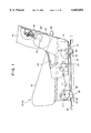
- FIG. 1 is a side view showing a seat according to the present invention
- FIG. 2 is a side view showing the detailed structure of the seat shown in FIG. 1;
- FIG. 3 is a plan view showing the seat shown in FIG. 1;
- FIG. 4 is an enlarged side view showing the front portion of the seat frame of the seat shown in FIG. 1;
- FIG. 5 is an enlarged side view showing the rear portion of the seat frame of the seat shown in FIG. 1;
- FIG. 6 is an enlarged side view used to explain the transfer mechanism of the seat shown in FIG. 1;
- FIG. 7 is a perspective view showing the seat folded and locked to the floor in accordance with the present invention.
- FIG. 8 illustrates pictorially how the seat shown in FIG. 1 is folded and removed according to the present invention
- FIG. 9 is a side view showing a conventional seat
- FIG. 10 is a side view showing the conventional seat shown in FIG. 9.
- FIG. 11 is a side view showing another conventional seat.
- right and left rear seats 13 and 14 are disposed behind the right and left front seats 11 and 12 of a vehicle.
- Each of the right and left rear seats 13 and 14 has a seat cushion 15 and a seat back 16 rotatably supported on the rear portion of the seat cushion 15.
- the seat back 16 can be locked at a predetermined angular position with respect to the seat cushion 15.
- the rear seats 13 and 14 can be folded by tilting up the seat cushion 15 along with the seat back 16 from the forward reclined position when the seat back 16 is reclined fully forward. Furthermore, the rear seats 13 and 14 can be removed from the floor when they are in the folding positions.
- the seat cushion 15 of the rear seat 13 is mounted on right and left seat frames 21, 21, each of which extends in a fore-and-aft (longitudinal) direction of the vehicle.
- FIGS. 1 through 5 the left side is forward and the right side is rearward with respect to a passenger seated.
- connecting brackets 22, 22 extend upward from the rear ends of the seat frames 21, 21, respectively.
- the seat back 16 is rotatably supported at its lower end by the connecting brackets 22, 22.
- the seat 13 is equipped with a reclining mechanism (not shown).
- the reclining mechanism can adjust the angular position of the seat back 16 by the operation of a reclining lever 24.
- the seat back 16 can be reclined fully forward by the operation of a forward reclining lever 25 so that the seat back 16 and the seat cushion 15 are closely attached with each other.
- the front lower portion of the seat frame 21 is provided with a front lock mechanism 26 engageable with a first striker 35 and a third striker 34 both of which are secured to the floor 28.
- the front lock mechanism 26 has the function of rotatably and removably locking the front lower portion of the seat frame 21 to the floor 28 and also has the function of maintaining the folding position of the seat 13 in the folding position.
- the rear lower portion of the seat frame 21 is provided with a rear lock mechanism 27 engageable with a second striker 36 secured to the floor 28.
- the rear lock mechanism 27 has the function of locking the rear lower portion of the seat frame 21 removably to the floor 28.
- right and left reinforcing members 31, 31 are attached to the floor 28 along the longitudinal direction of the vehicle, and a front opening 32 and a rear opening 33 are formed in the front and rear upper surfaces of each reinforcing member 31.
- the first and third strikers 35 and 34 are secured to fore and aft edges of the front opening 32, respectively, while the second striker 36 is secured to a fore edge of the rear opening 33.
- the front and rear openings 32 and 33 have front and rear covers 37 and 38 attached thereto, respectively.
- first support brackets 41, 41 are rotatably supported on the front portions of the right and left seat frames 21, 21.
- the right and left seat frames 21, 21 are rotatable around an axis X with respect to the first support brackets 41, 41.
- the right and left first support brackets 41, 41 are connected together by an auxiliary lever 42 having an intermediate crank portion. Therefore, the right and left support brackets 41, 41 and the auxiliary lever 42 can rotate as a unit with respect to the seat frames 21, 21.
- Each of the support brackets 41, 41 is provided at the lower end thereof with a guide portion 43 which can be inserted into or removed from the front opening 32.
- the guide portion 43 further includes a hook portion 44, which is in turn engageable with the third striker 34.
- a spring 45 is interposed between the seat frame 21 and the first support bracket 41 to urge the seat frame 21 to rotate in a counterclockwise direction in FIG. 2 with respect to the first support bracket 41.
- Right and left locking plates 46, 46 as first locking members, are rotatably supported on the right and left first support brackets 41, 41, respectively.
- the right and left first locking plates 46, 46 are connected together by a first lever 30 having an intermediate crank portion. Therefore, the right and left first locking plates 46, 46 and the first lever 30 can rotate as a unit with respect to the first brackets 41, 41.
- Each of the first locking plates 46, 46 is provided integrally, at the lower end thereof, with a guide portion 47 which can be inserted into or removed from the front opening 32. Furthermore, the guide portion 47 includes a first slot 48 which can receive the first striker 35.
- each of the first locking plates 46, 46 has a locking position in which the first striker 35 is received within the first slot 48 and an unlocking position in which the first striker 35 is located outside the first slot 48.
- a spring 49 is interposed between an arm 92 connected to the first lever 30 and another arm 94 connected to the auxiliary lever 42 to urge the first locking plate 46 to rotate in the counterclockwise direction in FIG. 2 with respect to the first support bracket 41.
- a third locking plate 50 as a third locking member, is rotatably supported around a support shaft 51.
- a coil spring 52 is wound around the support shaft 51 to urge the third locking plate 50 to rotate in the clockwise direction in FIG. 4 with respect to the seat frame 21.
- the lower portion of the third locking plate 50 is provided integrally with a guide portion 53 which can be inserted into or removed from the front opening 32. Furthermore, the guide portion 53 includes a third slot 54 which can receive the third striker 34.
- the locking plate 50 has a holding position in which the third striker 34 is received within the third slot 54 and a releasing position in which the third striker 34 is located outside the third slot 54.
- a guide pin 55 is attached to the third locking plate 50, while the first support bracket 41 has a corresponding guide slot 57 into which the guide pin 55 projects.
- a protruding portion 58 is formed integrally on the first locking plate 46 adjacent to the third locking plate 50, and a releasing pin 59 is attached to the third locking plate 50.
- the guide pin 55 of the third locking plate 50 will be moved along the guide slot 57 of the first support bracket 41 according to the upward rotation of the seat frame 21.
- the movement of the guide pin 55 causes the third locking plate 50 to rotate in the clockwise direction in FIGS. 2 and 4 with respect to the seat frame 21.
- the third slot 54 of the third locking plate 50 engages with the third striker 34, whereby the seat frame 21 (rear seat 13) is locked to the floor 28 in the folding position.
- the first lever 30 is rotated in the clockwise direction in FIG. 2 toward the auxiliary lever 42, the first locking plate 46 will be rotated in the same direction and the first slot 48 of the first locking plate 46 will be disengaged from the first striker 35.
- the clockwise rotation of the first locking plate 46 causes the protruding portion 58 of the first locking plate 46 to push up the releasing pin 59 on the third locking plate 50, whereby the third locking plate 50 is disengaged from the third striker 34. Therefore, the engagement between the seat frame 21 and the floor 28 is released. In this state It is possible either to return the rear seat 13 to the seating position by the rear downward rotation of the seat frame 21 or to remove the rear seat 13 by the upward lifting of the seat frame 21.
- second support brackets 61, 61 are rotatably supported on the rear portions of the right and left frames 21, 21.
- the second support brackets 61, 61 are connected together by a connecting rod 62. Therefore, the right and left second support brackets 61, 61 and connecting rod 62 can rotate as a unit with respect to the right and left frames 21, 21.
- Each of the second support brackets 61, 61 is provided, at the lower end thereof, with a guide portion 63 which can be inserted into or removed from the aforementioned rear opening 33, and at the upper end thereof with a cable tube attaching portion.89 to which a cable tube is attached.
- Second locking plates 64, 64 as second locking members, are rotatably supported on the right and left second support brackets 61, 61, respectively.
- the second locking plates 64, 64 are connected together by a connecting rod 65. Therefore, the right and left second locking plates 64, 64 and the connecting rod 65 can rotate as a unit with respect to the second support brackets 61, 61.
- Each of the second locking plates 64, 64 is provided integrally at the lower end thereof with a guide portion 66 which can be inserted into or removed from the rear opening 33.
- This guide portion 66 includes a second slot 67 which can receive the second striker 36 therein.
- cam members 68, 68 are rotatably supported adjacent to the second locking plates 64, 64, respectively, by a support shaft 69.
- Each of the cam members 68, 68 has a cam surface 70, which is in turn engageable with the abutting surface 71 of the second locking plate 64.
- a cable connecting lever 72 is connected to each of the cam members 68, 68, and each pair of the cam member 68 and cable connecting lever 72 can rotate as a unit with respect to the second support bracket 61.
- a spring 73 is interposed between the cam member 68 and the second locking plate 64, and as shown in FIG. 5, the spring 73 urges the cam member 68 to rotate in the clockwise direction and the second locking plate 64 to rotate in the counterclockwise direction, respectively.
- front and rear connecting arms 74 and 75 extend from the auxiliary lever 42 and the connecting rod 62, respectively.
- the front connecting arm 74 and rear connecting arm 75 are connected by a connecting link 76. Therefore, the first and second support brackets 41 and 61 are rotatable in synchronization with each other with respect to the seat frame 21.
- the third slot 54 of the third locking plate 50 will engage with the third striker 34, whereby the seat frame 21 (rear seat 13) will be locked in the folding position with respect to the floor 28.
- a second lever 29 for rotating the second locking plate 64 and the third locking plate 50 is attached to the rear surface of the seat back 16.
- the rear seat 13 is equipped with right and left transfer mechanisms 77, 77.
- Each transfer mechanism 77 inhibits the second lever 29 from rotating the third locking plates 50, 50 when the rear seat 13 is in the seating position and also allows the second lever 29 to rotate the third locking plates 50, 50 when the rear seat 13 is in the folding position.
- each support bracket 78 has cable tube attaching portions 79, 80, and 81 to which cable tubes are respectively attached.
- a lateral rod 83 extending in the lateral direction of the seat 13 is rotatably supported by the support brackets 78, 78.
- Transfer links 82, 82 are fixed near the opposite end portions of the lateral rod 83.
- Each transfer link 82 is formed integrally with cable connecting portions 84, 85, and 86 to which the end portions of cables 87, 88, and 90 are respectively connected.
- the second lever 29 on the rear surface of the seat back 16 and the cable connecting portion 84 of each transfer link 82 are connected together by the first cable 87 through the cable tube attaching portion 79. That is, a pair of first cables 87, 87 are disposed between the second lever 29 and the right cable connecting section 84 and between the second lever 29 and the left cable connecting section 84, respectively.
- the cable connecting lever 72 which is integral with the cam member 68, and the cable connecting portion 85 of the transfer link 82 are connected together by the second cable 88 through the cable tube attaching portions 80 and 89.
- a pair of second cables 88, 88 are disposed between the left cable connecting lever 72 and the left cable connecting sections 84 and between the right cable connecting lever 72 and the right cable connecting sections 84, respectively.
- the guide pin 55 of the third locking plate 50 and the cable connecting portion 86 of the transfer link 82 are connected together by the third cable 90 through the cable tube attaching portion 81. Namely, a single third cable 90 is disposed between the third locking plate 50 and one of the right and left transfer links 82, 82.
- lost motion stroke S1 is provided between the end portion 90a of the third cable 90 (indicated by a two-dotted line in FIG. 6) and the cable connecting portion 86 of the transfer link 82, as shown in FIGS. 2 and 6.
- the lost motion stroke S1 is absorbed by rotation of the third locking plate 50, so that the end portion 90a of the third cable 90 (indicated by a solid line in FIG. 6) and the cable connecting portion 86 of the transfer link 82 are closely attached with each other.
- lost motion stroke S2 is provided between the end portion 88a of the second cable 88 and the cable connecting portion 85 of each transfer link 82, as shown in FIG. 6.
- each of the first cables 87, 87 will be pulled up and each transfer link 82 will be rotated in the clockwise direction in FIG. 2.
- each of the second cables 88, 88 is pulled and each cam member 68 is rotated in the counterclockwise direction in FIG. 2.
- each of the second locking plates 64, 64 are also rotated in the counterclockwise direction, whereby the engagement between the second slot 67 of the second locking plate 64 and the second striker 36 is released.
- the rear seat 13 can be tilted up toward the forward direction.
- the rear seat 13 When, on the other hand, the rear seat 13 is in the folding position, if the passenger operates the second lever 29, the third cable 90 will be pulled according to the rotation of the transfer link 82, because the end portion 90a of the third cable 90 and the cable connecting portion 86 of the transfer link 82 are in contact with each other. This causes the third locking plate 50 to rotate in the counterclockwise direction in FIG. 2, whereby the engagement between the third slot 54 of the third locking plate 50 and the third striker 34 is released. Therefore, the rear seat 13 can be returned to the seating position.
- the hook portion 44 of the first support bracket 41 engages the third striker 34 and also the first slot 48 of the first locking plate 46 engages the first striker 35.
- the second slot 67 of the second locking plate 64 engages the second striker 36. Therefore, the seat frame 21 is reliably locked to the floor 28 at the front and rear portions thereof.
- the seat back 16 is first tilted forward from the locked position denoted as 13a to the forward reclined position denoted as 13b by the operation of the forward tilting lever 25 so that the seat back 16 is closely attached to the seat cushion 15. Then, if the passenger pulls up the second lever 29, the transfer link 82 will be rotated in the clockwise direction through the first cable 87, and the cam member 68 of the rear lock mechanism 27 will be rotated in the counterclockwise direction through the second cable 88.
- the seat 13 can be tilted up and forward.
- the lost motion stroke S1 is provided between the end portion 90a of the third cable 90 and the cable connecting portion 86 of the transfer link 82. Therefore, even if the passenger operates the second lever 29, the third cable 90 will not be pulled.
- the seat frame 21 is locked to the floor 28 in the folding position, and as shown by a two-dotted line in FIG. 2, the rear lock mechanism 27 is housed within the tilted seat frame 21.
- the first locking plate 46 will be disengaged from the first striker 35 and the third locking plate 50 will be disengaged from the third striker 34.
- the seat can be removed from the floor 28, as denoted at 13d in FIG. 8.
- the guide portions 43, 47, and 53 of the front lock mechanism 26 are first inserted into the front opening 32. With this insertion, the first slot 48, third slot 54, and hook portion 44 are caused to engage with the first and third strikers 34 and 33, respectively. Thus, as denoted at 13c in FIG. 8, the seat is locked in the folding position.
- the returning operation can be performed from either the front or the rear of the seat 13.
- the first lever 30 can be operated from the rear of the seat 13.
- the first locking plate 46 will be rotated and therefore the protruding portion 58 of the first locking plate 46 will push up the releasing pin 59 of the third locking plate 50.
- the third locking plate 50 is rotated in the counterclockwise direction and the third slot 54 is disengaged from the third striker 34.
- the end portion 90a of the third cable 90 and the cable connecting portion 86 of the transfer link 82 are closely attached with each other. Therefore, if the passenger operates the second lever 29, the third cable 90 will be pulled through the first cable 87 and transfer link 82. This causes the guide pin 55 of the third locking plate 50 to move along the guide slot 57, whereby the third slot 54 of the third locking plate 50 is disengaged from the third striker 34.
- the lost motion stroke S2 is provided between the end portion 88a of the second cable 88 and the cable connecting portion 85 of the transfer link 82. For this reason, even if the passenger operates the second lever 29, the second cable 88 will not be pulled. Therefore, since the spring force of the spring 73, which is interposed between the cam member 68 and the second locking plate 64, is not transferred to the second lever 29 through the second cable 88, the passenger can easily operate the second lever 29.
- the seat can be locked with reliability to the floor, even when the seat is in the folding position. Furthermore, multiple lock mechanisms can be operated by a single lever, so the seat folding and removing operations become easy.
- the lock mechanism applicable to the present invention is not limited to the structure employed in the aforementioned embodiment.
- the seats are arranged along the longitudinal direction of the vehicle, they may be arranged along the lateral direction.
Landscapes
- Engineering & Computer Science (AREA)
- Aviation & Aerospace Engineering (AREA)
- Transportation (AREA)
- Mechanical Engineering (AREA)
- Seats For Vehicles (AREA)
Abstract
Description
Claims (35)
Applications Claiming Priority (4)
| Application Number | Priority Date | Filing Date | Title |
|---|---|---|---|
| JP27589297A JP3426932B2 (en) | 1997-10-08 | 1997-10-08 | Foldable seat structure with detachable mechanism |
| JP9-275892 | 1997-10-08 | ||
| JP9-276804 | 1997-10-09 | ||
| JP27680497A JP3426933B2 (en) | 1997-10-09 | 1997-10-09 | Seat device |
Publications (1)
| Publication Number | Publication Date |
|---|---|
| US6065804A true US6065804A (en) | 2000-05-23 |
Family
ID=26551661
Family Applications (1)
| Application Number | Title | Priority Date | Filing Date |
|---|---|---|---|
| US09/168,172 Expired - Lifetime US6065804A (en) | 1997-10-08 | 1998-10-08 | Removable folding seat |
Country Status (3)
| Country | Link |
|---|---|
| US (1) | US6065804A (en) |
| DE (1) | DE19846031C2 (en) |
| FR (1) | FR2769268B1 (en) |
Cited By (34)
| Publication number | Priority date | Publication date | Assignee | Title |
|---|---|---|---|---|
| US6158800A (en) * | 1995-09-25 | 2000-12-12 | Chuo Hatsujo Kabushiki Kaisha | Foldable device for a recline seat of an automobile |
| US6234552B1 (en) * | 1999-02-23 | 2001-05-22 | Witte-Velbert Gmbh & Co. Kg | Fastening device for seats, seat benches or the like on the floor of a motor vehicle or the like |
| US6250704B1 (en) * | 1999-08-12 | 2001-06-26 | Dura Automotive Systems Inc. | Release mechanism for fold and flip seat assembly |
| US6283550B1 (en) * | 1998-06-26 | 2001-09-04 | Bertrand Faure Equipements Sa | Vehicle seat with automatic front anchoring, and vehicle comprising such a seat |
| FR2811273A1 (en) * | 2000-07-10 | 2002-01-11 | Faure Bertrand Equipements Sa | Automobile tipping seat anchoring foot comprises connection leg integral with seat frame pivoted on foot, leg comprises arm supported on pivoting catch stop |
| US6361098B1 (en) * | 1999-03-17 | 2002-03-26 | Daimlerchrysler Corporation | Seat riser fold and tumble mechanism |
| US6375245B1 (en) * | 2000-10-09 | 2002-04-23 | Johnson Controls Technology Company | Vehicle seating system having chuck reducing apparatus |
| US6412849B1 (en) * | 1999-12-06 | 2002-07-02 | Fisher Dynamics Corporation | Chuck-free latch assembly |
| US6478358B1 (en) * | 1998-12-18 | 2002-11-12 | Aisin Seiki Kabushiki Kaisha | Seat device for a vehicle |
| US20030193228A1 (en) * | 2002-04-11 | 2003-10-16 | Gilles Duquesnay | Fixing device for fixing a seat to a vehicle floor, and a seat equipped with such a fixing device |
| FR2838392A1 (en) * | 2002-04-11 | 2003-10-17 | Faurecia Sieges Automobile | Lock for attaching rail on car seat to chassis comprises plate mounted on rail which is pushed down into slot in seating on floor and is fitted with swiveling hooks mounted in channel at base of plate |
| WO2004026622A1 (en) * | 2002-09-20 | 2004-04-01 | Intier Automotive Inc. | Stow in floor seat assembly with main lateral displacement |
| US20040075292A1 (en) * | 2000-05-26 | 2004-04-22 | Peter Rausch | Seat module |
| US20040104589A1 (en) * | 2002-07-29 | 2004-06-03 | Aisin Seiki Kabushiki Kaisha | Seat apparatus for a vehicle |
| US20040183327A1 (en) * | 2002-12-24 | 2004-09-23 | Aisin Seiki Kabushiki Kaisha | Vehicle seat apparatus |
| US20050062326A1 (en) * | 2003-08-11 | 2005-03-24 | Kim Jong Ho | Locking device for a detachable vehicle seat |
| FR2868740A1 (en) * | 2004-04-13 | 2005-10-14 | Faurecia Sieges Automobile | Motor vehicle seat fixing device, has base mounted pivotally on anchoring fork around pivoting axle between use and tilted positions, and indentation, locking hook and stop pin to block pivoting of base with respect to anchoring fork |
| US20060006687A1 (en) * | 2004-07-09 | 2006-01-12 | Jeong Chan H | Double-foldinging seat for vehicles |
| US20060012231A1 (en) * | 2004-07-13 | 2006-01-19 | Dae Won San Up Co., Ltd. | Detachable seat for automobiles |
| US7000990B1 (en) * | 2005-03-22 | 2006-02-21 | Porter Group Llc | Recliner for vehicle foldable seat |
| US20060097560A1 (en) * | 2004-10-28 | 2006-05-11 | Lear Corporation | Remote release actuating system for a seat assembly |
| US20070052255A1 (en) * | 2005-09-06 | 2007-03-08 | Lear Corporation | Seat assembly with a release system |
| US20070080554A1 (en) * | 2005-10-06 | 2007-04-12 | Toyo Seat Usa Corporation | Latch mechanism for automotive seat assembly |
| US20070182231A1 (en) * | 2005-10-11 | 2007-08-09 | Tavis Lutzka | Rear row vehicle seat incorporating combination seatback, front and rear floor latches interengageable for selective dump and tumble and including a separate user engageable module operable with said front and rear floor latches for effectuating rearward seat removal |
| US20080012379A1 (en) * | 2005-12-21 | 2008-01-17 | Miller Michael P | Front latch assembly for vehicle seat cushion |
| WO2008098200A3 (en) * | 2007-02-08 | 2008-10-23 | Johnson Controls Tech Co | Fold and tumble seat |
| US20090230744A1 (en) * | 2006-04-06 | 2009-09-17 | Szybisty Robert J | Stand up seat |
| US20090273211A1 (en) * | 2005-05-13 | 2009-11-05 | Johnson Controls Technology Company | Vehicle seating system |
| US20100320812A1 (en) * | 2009-06-18 | 2010-12-23 | Toyota Motor Engineering & Manufacturing North America, Inc. | Single motion load bearing release handle |
| US20130341953A1 (en) * | 2010-11-15 | 2013-12-26 | David A. White | One Touch Stow In Floor Seat Assembly With Automatic Lateral Displacement |
| US20150123443A1 (en) * | 2012-06-13 | 2015-05-07 | Johnson Controls Gmbh | Hinge mechanism for a vehicle seat and method for operating a vehicle seat |
| US9393887B1 (en) * | 2015-03-27 | 2016-07-19 | Konstantinos Beis | Portable seat assembly |
| US10618430B2 (en) * | 2018-05-09 | 2020-04-14 | Polaris Industries Inc. | Seat latch mechanism |
| US11447040B2 (en) * | 2019-07-26 | 2022-09-20 | Polaris Industries Inc. | Side-by-side vehicle |
Families Citing this family (9)
| Publication number | Priority date | Publication date | Assignee | Title |
|---|---|---|---|---|
| DE19822262A1 (en) * | 1998-05-18 | 1999-11-25 | Lear Corp | Vehicle seat fitting device |
| JP4147564B2 (en) * | 1998-09-21 | 2008-09-10 | アイシン精機株式会社 | Vehicle seat support device |
| DE10034019B4 (en) * | 2000-07-07 | 2009-01-22 | Volkswagen Ag | Fastening device, in particular for a vehicle seat |
| DE10042115A1 (en) * | 2000-08-28 | 2002-03-14 | Burger Soehne | Locking system for car seat has front and rear indicator levers which are connected and control lever which can only be operated when lever at front is engaged with locking bolt and front indicator lever is in free position |
| DE10047744A1 (en) * | 2000-09-27 | 2002-04-11 | Bayerische Motoren Werke Ag | Vehicle with at least three rows of seats has seats in rows behind the first which can be adjusted to three positions when they are not in use |
| DE10052090C1 (en) * | 2000-10-20 | 2001-12-20 | Keiper Gmbh & Co | Release mechanism, for automobile passenger seat with fold-down backrest, has common operating element for releasing backrest and for releasing seat part to allow removal from automobile body |
| DE10217196C1 (en) * | 2002-04-18 | 2003-07-03 | Faurecia Autositze Gmbh & Co | Fastening for pivoting motor vehicle seat section has pin and bearing with stop to retain seat section in use position |
| JP2004058830A (en) * | 2002-07-29 | 2004-02-26 | Aisin Seiki Co Ltd | Seat device |
| DE10348303B4 (en) * | 2003-10-17 | 2005-07-21 | Keiper Gmbh & Co. Kg | Automotive seat back and base frame release locking mechanism ha hand lever located between backrest pivot and floor fixtures |
Citations (9)
| Publication number | Priority date | Publication date | Assignee | Title |
|---|---|---|---|---|
| US5238285A (en) * | 1992-07-16 | 1993-08-24 | Douglas & Lomason Company | Folding vehicle bedseat |
| JPH05262170A (en) * | 1991-12-12 | 1993-10-12 | Bertrand Faure Automob Bfa | Movable seat for vehicle |
| US5282662A (en) * | 1992-12-14 | 1994-02-01 | General Motors Corporation | Rear seat for all purpose vehicle |
| US5498051A (en) * | 1994-03-07 | 1996-03-12 | Hoover Universal, Inc. | Tumble forward seat |
| US5577805A (en) * | 1995-10-10 | 1996-11-26 | General Motors Corporation | Van-type vehicle seat |
| US5626391A (en) * | 1995-05-25 | 1997-05-06 | Bertrand Faure Ltd. | Uptiltable rear vehicle seat assembly |
| US5634686A (en) * | 1995-03-21 | 1997-06-03 | Aisin Seiki Kabushiki Kaisha | Seat device for vehicles |
| US5671965A (en) * | 1996-03-26 | 1997-09-30 | Atoma International, Inc. | Tumble seat with displaceable side handle release |
| US5810443A (en) * | 1995-12-22 | 1998-09-22 | Cesa - Compagnie Europeenne De Sieges Pour Automobiles | Seat structure having a variable configuration for a motor vehicle |
Family Cites Families (5)
| Publication number | Priority date | Publication date | Assignee | Title |
|---|---|---|---|---|
| US4865377A (en) * | 1987-12-31 | 1989-09-12 | Knusaga Corporation | Seat riser |
| FR2700735B1 (en) * | 1993-01-27 | 1995-04-07 | Matra Automobile | Removable and adjustable vehicle seat in position. |
| US5372398A (en) * | 1993-04-02 | 1994-12-13 | Chrysler Corporation | Vehicle seat assembly with retracting latch/engaging roller seat-to-floor lock |
| US5393116A (en) * | 1993-10-25 | 1995-02-28 | General Motors Corporation | Van-type vehicle multi-positional seat |
| DE19544833C2 (en) * | 1995-12-01 | 2001-06-21 | Brose Fahrzeugteile | Device for releasably connecting a vehicle seat to the vehicle floor |
-
1998
- 1998-10-06 DE DE19846031A patent/DE19846031C2/en not_active Expired - Lifetime
- 1998-10-08 FR FR9812627A patent/FR2769268B1/en not_active Expired - Lifetime
- 1998-10-08 US US09/168,172 patent/US6065804A/en not_active Expired - Lifetime
Patent Citations (11)
| Publication number | Priority date | Publication date | Assignee | Title |
|---|---|---|---|---|
| JPH05262170A (en) * | 1991-12-12 | 1993-10-12 | Bertrand Faure Automob Bfa | Movable seat for vehicle |
| US5330245A (en) * | 1991-12-12 | 1994-07-19 | Bertrand Faure Automobile "Bfa" | Movable vehicle seat |
| EP0546908B1 (en) * | 1991-12-12 | 1995-09-06 | Bertrand Faure Automobile "B.F.A." | Movable seat for a vehicle |
| US5238285A (en) * | 1992-07-16 | 1993-08-24 | Douglas & Lomason Company | Folding vehicle bedseat |
| US5282662A (en) * | 1992-12-14 | 1994-02-01 | General Motors Corporation | Rear seat for all purpose vehicle |
| US5498051A (en) * | 1994-03-07 | 1996-03-12 | Hoover Universal, Inc. | Tumble forward seat |
| US5634686A (en) * | 1995-03-21 | 1997-06-03 | Aisin Seiki Kabushiki Kaisha | Seat device for vehicles |
| US5626391A (en) * | 1995-05-25 | 1997-05-06 | Bertrand Faure Ltd. | Uptiltable rear vehicle seat assembly |
| US5577805A (en) * | 1995-10-10 | 1996-11-26 | General Motors Corporation | Van-type vehicle seat |
| US5810443A (en) * | 1995-12-22 | 1998-09-22 | Cesa - Compagnie Europeenne De Sieges Pour Automobiles | Seat structure having a variable configuration for a motor vehicle |
| US5671965A (en) * | 1996-03-26 | 1997-09-30 | Atoma International, Inc. | Tumble seat with displaceable side handle release |
Cited By (61)
| Publication number | Priority date | Publication date | Assignee | Title |
|---|---|---|---|---|
| US6158800A (en) * | 1995-09-25 | 2000-12-12 | Chuo Hatsujo Kabushiki Kaisha | Foldable device for a recline seat of an automobile |
| US6283550B1 (en) * | 1998-06-26 | 2001-09-04 | Bertrand Faure Equipements Sa | Vehicle seat with automatic front anchoring, and vehicle comprising such a seat |
| US6478358B1 (en) * | 1998-12-18 | 2002-11-12 | Aisin Seiki Kabushiki Kaisha | Seat device for a vehicle |
| US6234552B1 (en) * | 1999-02-23 | 2001-05-22 | Witte-Velbert Gmbh & Co. Kg | Fastening device for seats, seat benches or the like on the floor of a motor vehicle or the like |
| US6361098B1 (en) * | 1999-03-17 | 2002-03-26 | Daimlerchrysler Corporation | Seat riser fold and tumble mechanism |
| US6250704B1 (en) * | 1999-08-12 | 2001-06-26 | Dura Automotive Systems Inc. | Release mechanism for fold and flip seat assembly |
| US6412849B1 (en) * | 1999-12-06 | 2002-07-02 | Fisher Dynamics Corporation | Chuck-free latch assembly |
| US7270362B2 (en) * | 2000-05-26 | 2007-09-18 | Brose Fahrzeugteile Gmbh & Co., Kg, Coburg | Seat module |
| US20040075292A1 (en) * | 2000-05-26 | 2004-04-22 | Peter Rausch | Seat module |
| US6561583B2 (en) | 2000-07-10 | 2003-05-13 | Faurecia Sieges D'automobile S.A. | Mechanism for joining a removable seat with tilting seat pan to the floor of an automobile vehicle |
| FR2811273A1 (en) * | 2000-07-10 | 2002-01-11 | Faure Bertrand Equipements Sa | Automobile tipping seat anchoring foot comprises connection leg integral with seat frame pivoted on foot, leg comprises arm supported on pivoting catch stop |
| US6375245B1 (en) * | 2000-10-09 | 2002-04-23 | Johnson Controls Technology Company | Vehicle seating system having chuck reducing apparatus |
| US20030193228A1 (en) * | 2002-04-11 | 2003-10-16 | Gilles Duquesnay | Fixing device for fixing a seat to a vehicle floor, and a seat equipped with such a fixing device |
| FR2838392A1 (en) * | 2002-04-11 | 2003-10-17 | Faurecia Sieges Automobile | Lock for attaching rail on car seat to chassis comprises plate mounted on rail which is pushed down into slot in seating on floor and is fitted with swiveling hooks mounted in channel at base of plate |
| US6830295B2 (en) * | 2002-04-11 | 2004-12-14 | Faurecia Sieges D'automobile S.A. | Fixing device for fixing a seat to a vehicle floor, and a seat equipped with such a fixing device |
| US20040104589A1 (en) * | 2002-07-29 | 2004-06-03 | Aisin Seiki Kabushiki Kaisha | Seat apparatus for a vehicle |
| US6863330B2 (en) | 2002-07-29 | 2005-03-08 | Aisin Seiki Kabushiki Kaisha | Seat apparatus for a vehicle |
| US20060108822A1 (en) * | 2002-09-20 | 2006-05-25 | Tame Omar D | Stow in floor seat assembly with main lateral displacement |
| US20050230995A1 (en) * | 2002-09-20 | 2005-10-20 | Tame Omar D | Stow in floor seat assembly with main lateral displacement |
| US7121609B2 (en) | 2002-09-20 | 2006-10-17 | Intier Automotive Inc. | Stow in floor seat assembly with main lateral displacement |
| US7325850B2 (en) | 2002-09-20 | 2008-02-05 | Intier Automotive Inc. | Stow in floor seat assembly with main lateral displacement |
| WO2004026622A1 (en) * | 2002-09-20 | 2004-04-01 | Intier Automotive Inc. | Stow in floor seat assembly with main lateral displacement |
| US20040183327A1 (en) * | 2002-12-24 | 2004-09-23 | Aisin Seiki Kabushiki Kaisha | Vehicle seat apparatus |
| US6974173B2 (en) | 2002-12-24 | 2005-12-13 | Aisin Seiki Kabushiki Kaisha | Vehicle seat apparatus |
| US20050062326A1 (en) * | 2003-08-11 | 2005-03-24 | Kim Jong Ho | Locking device for a detachable vehicle seat |
| US7213881B2 (en) * | 2003-11-08 | 2007-05-08 | Kia Motors Corporation | Locking device for a detachable vehicle seat |
| FR2868740A1 (en) * | 2004-04-13 | 2005-10-14 | Faurecia Sieges Automobile | Motor vehicle seat fixing device, has base mounted pivotally on anchoring fork around pivoting axle between use and tilted positions, and indentation, locking hook and stop pin to block pivoting of base with respect to anchoring fork |
| CN100450817C (en) * | 2004-07-09 | 2009-01-14 | 起亚自动车株式会社 | Double-foldinging seat for vehicles |
| US20060006687A1 (en) * | 2004-07-09 | 2006-01-12 | Jeong Chan H | Double-foldinging seat for vehicles |
| US7134703B2 (en) * | 2004-07-09 | 2006-11-14 | Kia Motors Corporation | Double-folding seat for vehicles |
| US7152925B2 (en) * | 2004-07-13 | 2006-12-26 | Dae Won San Up Co., Ltd | Detachable seat for automobiles |
| US20060012231A1 (en) * | 2004-07-13 | 2006-01-19 | Dae Won San Up Co., Ltd. | Detachable seat for automobiles |
| US20060097560A1 (en) * | 2004-10-28 | 2006-05-11 | Lear Corporation | Remote release actuating system for a seat assembly |
| DE102005051298B4 (en) * | 2004-10-28 | 2007-12-13 | Lear Corporation, Southfield | Seat arrangement for a vehicle |
| US7320501B2 (en) | 2004-10-28 | 2008-01-22 | Lear Corporation | Remote release actuating system for a seat assembly |
| WO2006101612A1 (en) * | 2005-03-22 | 2006-09-28 | Porter Group Llc | Recliner for vehicle foldable seat |
| US7000990B1 (en) * | 2005-03-22 | 2006-02-21 | Porter Group Llc | Recliner for vehicle foldable seat |
| US8091945B2 (en) * | 2005-05-13 | 2012-01-10 | Johnson Controls Technology Company | Vehicle seating system |
| US20090273211A1 (en) * | 2005-05-13 | 2009-11-05 | Johnson Controls Technology Company | Vehicle seating system |
| US7309095B2 (en) | 2005-09-06 | 2007-12-18 | Lear Corporation | Seat assembly with a release system |
| US20070052255A1 (en) * | 2005-09-06 | 2007-03-08 | Lear Corporation | Seat assembly with a release system |
| US20070080554A1 (en) * | 2005-10-06 | 2007-04-12 | Toyo Seat Usa Corporation | Latch mechanism for automotive seat assembly |
| US7357436B2 (en) | 2005-10-06 | 2008-04-15 | Toyo Seat Usa Corporation | Latch mechanism for automotive seat assembly |
| US7500707B2 (en) * | 2005-10-11 | 2009-03-10 | Bae Industries, Inc. | Removable vehicle seat |
| US20070182231A1 (en) * | 2005-10-11 | 2007-08-09 | Tavis Lutzka | Rear row vehicle seat incorporating combination seatback, front and rear floor latches interengageable for selective dump and tumble and including a separate user engageable module operable with said front and rear floor latches for effectuating rearward seat removal |
| US7367604B2 (en) * | 2005-12-21 | 2008-05-06 | Porter Group, Llc | Front latch assembly for vehicle seat cushion |
| US20080012379A1 (en) * | 2005-12-21 | 2008-01-17 | Miller Michael P | Front latch assembly for vehicle seat cushion |
| US20090230744A1 (en) * | 2006-04-06 | 2009-09-17 | Szybisty Robert J | Stand up seat |
| US7997653B2 (en) * | 2006-04-06 | 2011-08-16 | Intier Automotive Inc. | Stand up seat |
| WO2008098200A3 (en) * | 2007-02-08 | 2008-10-23 | Johnson Controls Tech Co | Fold and tumble seat |
| US20110062761A1 (en) * | 2007-02-08 | 2011-03-17 | Johnson Controls Technology Company | Pivot retainer |
| US8840187B2 (en) | 2007-02-08 | 2014-09-23 | Johnson Controls Technology Company | Pivot retainer |
| US20100320812A1 (en) * | 2009-06-18 | 2010-12-23 | Toyota Motor Engineering & Manufacturing North America, Inc. | Single motion load bearing release handle |
| US7914077B2 (en) | 2009-06-18 | 2011-03-29 | Toyota Motor Engineering & Manufacturing North America, Inc. | Single motion load bearing release handle |
| US20130341953A1 (en) * | 2010-11-15 | 2013-12-26 | David A. White | One Touch Stow In Floor Seat Assembly With Automatic Lateral Displacement |
| US8864209B2 (en) * | 2010-11-15 | 2014-10-21 | Magna Seating Inc. | One touch stow in floor seat assembly with automatic lateral displacement |
| US20150123443A1 (en) * | 2012-06-13 | 2015-05-07 | Johnson Controls Gmbh | Hinge mechanism for a vehicle seat and method for operating a vehicle seat |
| US9440558B2 (en) * | 2012-06-13 | 2016-09-13 | Johnson Controls Technology Company | Hinge mechanism for a vehicle seat and method for operating a vehicle seat |
| US9393887B1 (en) * | 2015-03-27 | 2016-07-19 | Konstantinos Beis | Portable seat assembly |
| US10618430B2 (en) * | 2018-05-09 | 2020-04-14 | Polaris Industries Inc. | Seat latch mechanism |
| US11447040B2 (en) * | 2019-07-26 | 2022-09-20 | Polaris Industries Inc. | Side-by-side vehicle |
Also Published As
| Publication number | Publication date |
|---|---|
| DE19846031A1 (en) | 1999-04-22 |
| DE19846031C2 (en) | 2002-01-17 |
| FR2769268B1 (en) | 2000-11-10 |
| FR2769268A1 (en) | 1999-04-09 |
Similar Documents
| Publication | Publication Date | Title |
|---|---|---|
| US6065804A (en) | Removable folding seat | |
| US6250704B1 (en) | Release mechanism for fold and flip seat assembly | |
| EP1049602B1 (en) | Rotary recliner control mechanism for multifunction vehicle seal applications | |
| US7029063B2 (en) | Drop down stow in floor automotive vehicle seat assembly | |
| EP1214220B1 (en) | Easy entry seat track assembly | |
| US6290297B1 (en) | Latch assembly and seat hinge with interlock | |
| US8496294B2 (en) | Stand and stow seat for hybrid vehicles | |
| US7021716B2 (en) | Tip easy entry and fold flat recliner assembly | |
| EP1601549B1 (en) | Seat assembly with seat back lockout | |
| JP3228406B2 (en) | Vehicle seat attachment / detachment mechanism | |
| EP1606137B1 (en) | Seat back recliner for vehicles | |
| CA2498848C (en) | Stow in floor automotive seat assembly | |
| EP0925995B1 (en) | Seat structure for vehicle | |
| JPH11348626A (en) | Trunk-through device | |
| CA2368074C (en) | Safety mechanism for a fold and tumble seat assembly | |
| JP2000103271A (en) | Inverted seat | |
| JPH09207637A (en) | Vehicle seat storage structure | |
| JP3426932B2 (en) | Foldable seat structure with detachable mechanism | |
| JP2001047911A (en) | Vehicle seat mounting structure | |
| EP1593546B1 (en) | Drop down stow in floor automotive vehicle set assembly | |
| JP2958134B2 (en) | Vehicle seat | |
| JPH0522437Y2 (en) | ||
| JPH11105595A (en) | Automotive seat moving mechanism | |
| JPH02144235A (en) | Seat device for automobile | |
| JPH09193700A (en) | Locking mechanism for retractable rear seat backs for vehicles |
Legal Events
| Date | Code | Title | Description |
|---|---|---|---|
| AS | Assignment |
Owner name: MITSUBISHI JIDOSHA KOGYO KABUSHIKI KAISHA, JAPAN Free format text: ASSIGNMENT OF ASSIGNORS INTEREST;ASSIGNORS:TANAKA, MASAMI;MURINISHI, YASUJI;KUTOMI, SHINGO;AND OTHERS;REEL/FRAME:009658/0043 Effective date: 19980917 Owner name: KABUSHIKI KAISHA IMASEN DENKI SEISAKUSHO, JAPAN Free format text: ASSIGNMENT OF ASSIGNORS INTEREST;ASSIGNORS:TANAKA, MASAMI;MURINISHI, YASUJI;KUTOMI, SHINGO;AND OTHERS;REEL/FRAME:009658/0043 Effective date: 19980917 |
|
| AS | Assignment |
Owner name: MITSUBISHI JIDOSHA KOGYO KABUSHIKI KAISHA, JAPAN Free format text: CORRECTIVE ASSIGNMENT TO CORRECT THE NAME OF THE ASSIGNORS, FILED ON 12-23-98, RECORDED ON REEL 9658, FRAME 0043;ASSIGNORS:TANAKA, MASAMI;MORINISHI, YASUJI;KUTOMI, SHINGO;AND OTHERS;REEL/FRAME:010057/0335 Effective date: 19980917 Owner name: KABUSHIKI KAISHA IMASEN DENKI SEISAKUSHO, JAPAN Free format text: CORRECTIVE ASSIGNMENT TO CORRECT THE NAME OF THE ASSIGNORS, FILED ON 12-23-98, RECORDED ON REEL 9658, FRAME 0043;ASSIGNORS:TANAKA, MASAMI;MORINISHI, YASUJI;KUTOMI, SHINGO;AND OTHERS;REEL/FRAME:010057/0335 Effective date: 19980917 |
|
| STCF | Information on status: patent grant |
Free format text: PATENTED CASE |
|
| FEPP | Fee payment procedure |
Free format text: PAYOR NUMBER ASSIGNED (ORIGINAL EVENT CODE: ASPN); ENTITY STATUS OF PATENT OWNER: LARGE ENTITY |
|
| AS | Assignment |
Owner name: MITSUBISHI JIDOSHA KOGYO K.K. (A.K.A. MITSUBISHI M Free format text: CHANGE OF ADDRESS;ASSIGNOR:MITSUBISHI JIDOSHA KOGYO K.K.;REEL/FRAME:014601/0865 Effective date: 20030905 |
|
| FPAY | Fee payment |
Year of fee payment: 4 |
|
| AS | Assignment |
Owner name: MITSUBISHI JIDOSHA KOGYO K.K. (A.K.A. MITSUBISHI M Free format text: CHANGE OF ADDRESS;ASSIGNOR:MITSUBISHI JIDOSHA KOGYO K.K. (A.K.A. MITSUBISHI MOTORS CORPORATION);REEL/FRAME:019019/0761 Effective date: 20070101 |
|
| FPAY | Fee payment |
Year of fee payment: 8 |
|
| FPAY | Fee payment |
Year of fee payment: 12 |