US6062467A - Dispensing assembly for a lined carton and process and apparatus thereof - Google Patents
Dispensing assembly for a lined carton and process and apparatus thereof Download PDFInfo
- Publication number
- US6062467A US6062467A US09/050,533 US5053398A US6062467A US 6062467 A US6062467 A US 6062467A US 5053398 A US5053398 A US 5053398A US 6062467 A US6062467 A US 6062467A
- Authority
- US
- United States
- Prior art keywords
- liner
- front panel
- carton
- pour spout
- dispensing
- Prior art date
- Legal status (The legal status is an assumption and is not a legal conclusion. Google has not performed a legal analysis and makes no representation as to the accuracy of the status listed.)
- Expired - Fee Related
Links
Images


Classifications
-
- B—PERFORMING OPERATIONS; TRANSPORTING
- B65—CONVEYING; PACKING; STORING; HANDLING THIN OR FILAMENTARY MATERIAL
- B65D—CONTAINERS FOR STORAGE OR TRANSPORT OF ARTICLES OR MATERIALS, e.g. BAGS, BARRELS, BOTTLES, BOXES, CANS, CARTONS, CRATES, DRUMS, JARS, TANKS, HOPPERS, FORWARDING CONTAINERS; ACCESSORIES, CLOSURES, OR FITTINGS THEREFOR; PACKAGING ELEMENTS; PACKAGES
- B65D5/00—Rigid or semi-rigid containers of polygonal cross-section, e.g. boxes, cartons or trays, formed by folding or erecting one or more blanks made of paper
- B65D5/42—Details of containers or of foldable or erectable container blanks
- B65D5/72—Contents-dispensing means
- B65D5/74—Spouts
- B65D5/741—Spouts for containers having a tubular body
- B65D5/743—Spouts formed by deforming or tearing scored or incised parts of the side-wall of containers
- B65D5/744—Spouts formed by deforming or tearing scored or incised parts of the side-wall of containers combined with swivelling devices having a bottom-wall and two side-walls
-
- Y—GENERAL TAGGING OF NEW TECHNOLOGICAL DEVELOPMENTS; GENERAL TAGGING OF CROSS-SECTIONAL TECHNOLOGIES SPANNING OVER SEVERAL SECTIONS OF THE IPC; TECHNICAL SUBJECTS COVERED BY FORMER USPC CROSS-REFERENCE ART COLLECTIONS [XRACs] AND DIGESTS
- Y10—TECHNICAL SUBJECTS COVERED BY FORMER USPC
- Y10S—TECHNICAL SUBJECTS COVERED BY FORMER USPC CROSS-REFERENCE ART COLLECTIONS [XRACs] AND DIGESTS
- Y10S493/00—Manufacturing container or tube from paper; or other manufacturing from a sheet or web
- Y10S493/901—Rigid container
- Y10S493/906—Rigid container having multilayer wall
- Y10S493/907—Lined
Definitions
- This invention relates to the packaging of dry particulate foods such as ready-to-eat (“RTE”) cereal. More specifically, this invention relates to lined cartons with reclosable dispensing means connected to the liner in such a way that a portion thereof is separated from the liner upon initial opening to provide access to the contents of the carton.
- RTE ready-to-eat
- cartons with liner bags for dry particulate foods such as RTE cereal are well known.
- Such cartons are usually formed from a blank of paperboard or similar material comprising sidewalls and top and bottom flaps.
- the liner is a plastic or coated paper bag which holds the particulate food.
- the liner can be filled and sealed before or after being placed inside an open top carton, the top flaps of which are then folded and sealed.
- RTE cereal for example, has a low moisture content and readily absorbs moisture from the air leading to a loss of crispness.
- Dispensing devices such as pour spouts have been proposed to control the discharge of particulate product and minimize exposure to the atmosphere, however, when a carton with a pour spout contains a filled and sealed liner bag, the bag must be manually torn or cut with a knife or scissors when the spout if first opened.
- This arrangement has several drawbacks not the least of which is manually opening the liner bag. Once opened, and as the contents are depleted, the liner bag and its contents slide and shift positions in the carton which can cause the opened portion of the liner to become misaligned with the pour spout opening thereby hindering dispensing of product from the carton. This also causes product to drop between the carton and the liner.
- the present invention is directed towards an improved food carton with a pivotable pour spout mounted to a dispensing opening.
- a front panel of the pour spout is bonded to a portion of the liner bag and, when initially opened, that portion partly separates from the rest of the liner thereby providing access to the contents of the carton.
- the liner bonded to the front panel separates to create an opening while remaining integral with the liner along the pivot axis.
- closure of the pour spout minimizes contact of the contents with the outside atmosphere and maintains alignment between the liner opening and the pour spout opening.
- the liner can also be bonded adjacent the dispensing opening to further maintain alignment.
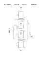
- FIGS. 1A and 1C are side views and FIG. 1B is a perspective view of the dispensing assembly of the invention shown partly open.
- FIG. 2 is a perspective view of the dispensing assembly of the invention shown fully open.
- FIGS. 3A and B are perspective views, partly broken away, showing the dispensing assembly partly open and fully open.
- FIGS. 3C and D are partial cross-sectional views showing the dispensing opening partly open and fully closed.
- FIG. 3E is a perspective view of an alternate notch shape.
- FIG. 4A is a plan view of the interior of a front panel of the dispensing assembly and FIG. 4B, 4C, 4D and 4E are cross-section views showing means to promote bonding between the front panel and the liner.
- FIG. 5 is a plan view of a pour spout assembly laid flat with its interior surfaces facing upwards.
- FIG. 6 is a plan view of a top insert laid flat with its interior surface facing upward.
- FIG. 7 is a diagrammatic view of apparatus for sealing the liner to the front panel of the pour spout.
- FIG. 8 is a perspective view of an alternate embodiment of the present invention partly broken away.
- FIG. 9 shows a perforation pattern on the liner of the embodiment of FIG. 8.
- FIG. 10 is a plan view of a material which partly forms the side panels of the embodiment of FIG. 8.
- U.S. Pat. No. 5,012,959 is illustrative of the first type and shows a plastic pour spout fitment in a precut dispensing opening of a paperboard carton. The fitment is attached by an adhesive or a plurality of rivets.
- Pour spout fitments may be made from any number of materials including, polyethylene, polypropylene, polystyrene, nylon ABS, paperboard and the like.
- a portion of the liner bag is brought into contact and bonded with the front panel of a pour spout mounted in a dispensing opening in a side panel of the carton.
- the preferred bonding medium is a hot melt adhesive. If the liner is in the carton, open and unfilled, simple means can be employed to clamp the liner and the front panel together and apply heat to heat seal to two surfaces together. Normally, in this embodiment, the hot melt adhesive is first applied in the desired pattern to the interior of the front panel of the pour spout.
- reduced pressure means such as a simple vacuum enclosure can be used to bring about a sealing contact between the liner and the front panel of the pour spout.
- An activatable hot melt adhesive is positioned in the desired pattern between the liner and the front panel and externally activated by delivering bonding energy to the interface. This can be done by including a heat generating substance in or with the hot melt adhesive that will generate heat to activate the adhesive.
- a heat generating substance in or with the hot melt adhesive that will generate heat to activate the adhesive.
- Such substances include metal foils such as aluminum foil laminated on one or both sides to a hot melt adhesive, metal salts such as magnesium chloride, chromium nitrate, aluminum chloride and the like, mixed with a hot melt adhesive or metal particles such as iron or aluminum powder mixed with or flocked onto a hot melt adhesive applied in the desired pattern to the front panel.
- a magnet When using magnetizable particles such as iron, a magnet can be employed to orient the particles and promote bonding with the liner.
- Metal salts and metal particles are used in amounts sufficient to activate the adhesive when external bonding energy is applied.
- Hot-melt adhesives are 100% solids and are applied in hot, molten form. They set fast when heat is removed and can be preapplied and reactivated later by the application of heat.
- Hot melt adhesives are typically formulated with a backbone polymer such as ethylene-vinyl acetate or polyethylene. The main polymer is usually let down with a diluent such as wax to improve melt flow properties.
- Antioxidants are a component since the adhesive is applied hot and is subject to oxidation. Tackifiers improve hot tack and viscosity. Other materials influence melt temperature. Added colorants can make the adhesive more visible.
- Hot-melt adhesives are readily available from numerous sources. INSTANT LOK® & hot melt adhesives from National Starch and Chemical Corporation of Bridgewater N.J. 08807 are suitable for use in the invention.
- a typical metal foil laminate includes aluminum foil, generally vacuum metalized aluminum on a polyester film, with a linear low density polyethylene adhesive on one or both sides.
- Curwood Inc. of Oshkosh, Wis. 54903, provides CURLAM® Grade 5432 film with adhesive on one side. It is preferred to coat both sides of the film with an adhesive which enables the use of induction heating to bond the foil laminate to the front panel and the liner at the same time.
- Induction heating equipment is widely used in the packaging field and suitable units for use in the invention are available from Lepel Corporation of Edgewood, N.Y. 11717 and Amertherm, Inc. of Scottsville, N.Y. 14546.
- the intensity and duration of the induction field required to bond the liner to the front panel depends on the composition of the heat activatable adhesive.
- an aluminum foil laminated with linear, low density polyethylene generally achieves its sealing temperature in 0.9 to 1.2 seconds when exposed to a Lepel, LEPAK, Jr. 750 watt induction sealer.
- induction heating systems and heat activatable adhesives can be adopted to the present invention.
- an induction heating system for sealing packages using magnetic susceptible particles and heat softenable adhesives and high frequency alternating magnetic fields is disclosed in U.S. Pat. No. 3,879,247 which is incorporated herein by reference.
- Polymer systems for sealing containers which can be activated by electromagnetic energy frequencies of 0.1-30,000 MHZ, including radio frequency and microwave heating, are disclosed in U.S. Pat. No. 4,787,194 which is incorporated herein by reference.
- RF sealable, non-foil acrylate based polymers for packaging applications are disclosed in WO 95/03939 which is also incorporated herein by reference.
- Heat sealing the liner to the front panel of the pour spout locally weakens the liner at the margins of the heat seal area which facilitates separation of a portion of the liner.
- This effect can be enhanced by attaching a laminate metal foil laminate to a raised area on the front panel with an overhang, that is, the size of the raised area is slight smaller than the area of the metal foil laminate.
- the edges of the foil laminate extend over the outside perimeter of the raised area and come in contact with the liner without contact with the front panel.
- the heat produced in the overhang area creates a thinned area or score line mirroring the shape of the overhang area.
- Other methods of scoring a liner include applying a metal containing substance, such as a metal foil or a metal ink, directly to the liner, and then exposing the liner to an induction field.
- a metal containing substance such as a metal foil or a metal ink
- the dispensing assembly of the invention shown generally by reference numeral 3, is mounted to a dispensing opening in carton 1.
- Carton 1 includes side walls 42, end walls 43 and top flaps 40 and 41.
- a sealed plastic liner bag 15 with product is in carton 1.
- Flap member 5 which is perforated from end wall 43 so as to pivot around axis 2 carries the pour spout which includes front panel 6 and side panels 7.
- pour spout 3 can be gained, in one embodiment shown in FIG. 1A, by removing strip 51 between perforated lines 4 via tab 5" thus is exposing an upper portion of front panel 6 as shown in FIG. 1B.
- flap 5 can abut cut line 4' in end wall 43 as shown in FIG. 1C.
- Line 4' is covered by a peal off tape which can be removed for initial opening of the pour spout 3.
- the pour spout assembly has side panels 7 joined to front panel 6 along fold lines 31.
- Side panels 7 have notches 36 and 37 for defining the closed and open position of the spout 3 as well as tabs 38 which prevent complete removal of the pour spout in the event the position defined by notches 37 is exceeded.
- Front panel 6 is secured to flap 5 using a suitable adhesive such as a hot melt adhesive while the box blank is still flat.
- the pour spout incorporates an upper member having a center section 11 and side members 11' which fold along fold lines 30.
- Center section 11 and side members 11' are adhered to the interior of side and end walls 42 and 43 with center section 11 positioned as shown in FIGS. 1B and 3A such that the upper portion of front panel 6 covers section 11 and terminates at line 4' in end wall 43.
- Center section 11 has two step down sections which interact with the side panels 7 and notches 36 and 37.
- the first step down section has detents or ends 34 and a width D1 which corresponds to width D1 of front panel 6.
- the second step down member has similar detents or ends 35 and a width D2 which is slightly larger than D1, the width of front panel 6, and thus slightly larger than the width of end wall 43. This provides a snap fit for opening and closing the pour assembly 3.
- side panels 7 pivot between side walls 42 and ends 35 of center section 11.
- ends 35 enter notches 37 because the distance D2 between ends 35, being greater than width D2 of panel 6, is also greater than the distance between notches 37.
- side panels 7 now rest against ends 34 of section 11 to keep them approximately parallel to side walls 42.
- ends 35 enter notches 36 with adjacent portions of side panels 7 again resting against ends 34 (FIG. 3D). This provides a snap like opening and closing by virtue of the greater distance between ends 35 and notches 37 in the open position and notches 36 in the closed position.
- FIG. 3E shows an alternate V shaped configuration for notch 37 in side walls 7 to facilitate opening and closing of the pour spout 3.
- front panel 6 carries means 9 for promoting bonding of a portion of the liner bag 15 to front panel 6 of the pour spout. Similar means 13 to bond liner 15 to end wall 43 above the pour spout are positioned on center section 11 facing the interior of the carton.
- Bonding means 9 is shown to have a generally rectangular shape which defines that portion of the liner bag 15 that separates from the liner as the pour spout pivots to open for the first time.
- Bonding member 9 can have dimensions approximating the rectangular shape of the front panel 6 or it can be reduced in size as shown in FIGS. 2 and 5.
- bonding member 9 is adhered to a raised portion 6' of front panel 6 which corresponds approximately to the rectangular shape of member 9. See FIG. 4A.
- member 9 includes a layer of metal foil 9a such as aluminum foil or vacuum metalized aluminum adhered to polyester layer 9b.
- Adhesive layers 9c and 9e flank both sides of the polyester/foil laminate.
- Linear low density polyethylene adhesive layers define the outermost layers 9d and 9f.
- the overall thickness of member 9 is about 5 mils and it can be adhered to raised area 6' of front panel 6 by spot glueing for positioning purposes.
- Bonding member 13 is of a similar construction and can also be spot glued in the position shown in FIG. 3A. Spot glueing of members 9 and 13 is preferred so as to activate both adhesive layers 9d and 9f at the same time as described below.
- carton 1 contains a filled and sealed liner bag 15.
- the filled carton is passed through enclosure 70 via air locks 72 and 73 which maintain an area of reduced pressure in the enclosure 70 via vacuum generator 71.
- sealed liner bag 15 contains atmospheric air, the application of a vacuum has the effect of inflating liner bag 15 forcing it tightly against the interior of the carton including foil laminate 9 and front panel 6. While in this state, the carton 1 enters a heating zone provided by induction heating device 21.
- a suitable induction heater is a Model XP20 made by Ameritherm Inc.
- Induction heat provided by member 21 heats the metal foil laminate member 9 which in turn activates adhesive layers 9d and 9f.
- Adhesive layer 9d adheres the foil laminate member 9 to raised area 6' of front panel 6 while adhesive layer 9e adheres the plastic liner bag 15 to the front panel 6 in an area defined by the rectangular shape of metal foil laminate member 9.
- member 9 overlaps raised area 6' leaving air spaces 50 heat generated by foil layer 9a becomes concentrated at the edges of the member 9 in the area of overhang which stretches and thins the bag liner 15 in the area shown by reference numeral 51. This thinning provides a score line in the bag liner 15 around the edges of member 9 to facilitate initial opening of the pour spout.
- portion 16, (FIG. 2), of liner bag 15 remains bonded to panel 6 via member 9 and separates on three sides 16a, 16b and 16c corresponding to the thinned or weakened score line formed in the area of 51 around the edges of the member 9.
- portion 16 of liner bag 15 separates from the main body of the liner bag and remains integral therewith along the pivot axis 2'.
- side panels 7 cooperate with ends 34 and 35 on member 11 to maintain alignment between portion 16 and opening 14 in the liner bag 15.
- metal foil laminate member 13 is positioned as shown in FIG. 6 to bond the liner bag adjacent the opening 14 above the opening formed by the dispensing assembly itself.
- Further alignment means can be provided by a series of dots or circles 13' (FIG. 1B) of the same metal foil laminate as member 9 positioned on side panels 42 adjacent the periphery of the side panels 7 when the pour spout is in a closed position.
- Members 13 and 13' bond the liner bag 15 to the carton walls via induction heating at the same time member 9 bonds the liner bag to front panel 6 (FIG. 7).
- FIGS. 4D and E show an alternate embodiment wherein a bead of hot melt adhesive 62 is applied to front panel 6 in the same pattern as member 9.
- the hot melt adhesive can be premixed with metal particles such as iron or aluminum or bead 62 can be flocked while still hot with iron or aluminum particles 61.
- a magnet can be used to orient iron particles 61 for better bonding to film 15 (FIG. 4E).
- FIG. 8 is a perspective of an alternate embodiment for a container of the present in invention.
- the pour spout 3 includes bezel 25 that is affixed directly to end wall 43, front panel 5 that is hingedly attached to bezel 7, and flexible side panels 80 which are attached to front panel 5 by conventional adhesive. Side panels 80 bond to liner 15 at seams 23. Bonding between the side panels 80 and the liner 15 is achieved by the process shown in FIG. 7.
- flexible side panels 80 pull and tear the liner 15 along lines of perforation 84 shown in FIG. 9. As flexible side panels 80 pull liner 15, portions 82 the liner extend and form the side walls spout 3 with side panels 80.
- Flexible side panels 80 are preferably formed by a single sheet of flexible material 86 as shown in FIG. 10 with conventional adhesive 27 applied to the edge which bonds to the pour spout front panel 5.
- Foil laminate bonding member 29 (similar to member 9) bonds to corresponding edges of portions 82 of liner 15 to form seams 23 in the side panels 80, 82.
Landscapes
- Engineering & Computer Science (AREA)
- Mechanical Engineering (AREA)
- Cartons (AREA)
Abstract
Description
Claims (18)
Priority Applications (10)
| Application Number | Priority Date | Filing Date | Title |
|---|---|---|---|
| US09/050,533 US6062467A (en) | 1997-12-17 | 1998-03-30 | Dispensing assembly for a lined carton and process and apparatus thereof |
| US09/150,966 US6145736A (en) | 1997-12-17 | 1998-09-10 | Dispensing assembly for a lined carton and process and apparatus thereof |
| JP2000538922A JP2002508283A (en) | 1997-12-17 | 1998-12-17 | Dispensing assembly for carton with liner and method and apparatus for manufacturing the same |
| AU20022/99A AU754011B2 (en) | 1997-12-17 | 1998-12-17 | Dispensing assembly for a lined carton and process and apparatus thereof |
| NZ505138A NZ505138A (en) | 1997-12-17 | 1998-12-17 | Dispensing assembly for a lined carton with spout such that on opening spout the liner separates to allow access to interior of carton |
| EP98964773A EP1037808A1 (en) | 1997-12-17 | 1998-12-17 | Dispensing assembly for a lined carton and process and apparatus thereof |
| US09/213,100 US6213388B1 (en) | 1997-12-17 | 1998-12-17 | Dispensing assembly for a lined carton and process and apparatus thereof |
| CA002309166A CA2309166A1 (en) | 1997-12-17 | 1998-12-17 | Dispensing assembly for a lined carton and process and apparatus thereof |
| PCT/US1998/026907 WO1999030974A1 (en) | 1997-12-17 | 1998-12-17 | Dispensing assembly for a lined carton and process and apparatus thereof |
| US09/699,300 US6474046B1 (en) | 1997-12-17 | 2000-10-27 | Method of induction sealing liners to cartons |
Applications Claiming Priority (2)
| Application Number | Priority Date | Filing Date | Title |
|---|---|---|---|
| US6985997P | 1997-12-17 | 1997-12-17 | |
| US09/050,533 US6062467A (en) | 1997-12-17 | 1998-03-30 | Dispensing assembly for a lined carton and process and apparatus thereof |
Related Child Applications (1)
| Application Number | Title | Priority Date | Filing Date |
|---|---|---|---|
| US09/150,966 Continuation-In-Part US6145736A (en) | 1997-12-17 | 1998-09-10 | Dispensing assembly for a lined carton and process and apparatus thereof |
Publications (1)
| Publication Number | Publication Date |
|---|---|
| US6062467A true US6062467A (en) | 2000-05-16 |
Family
ID=46203325
Family Applications (1)
| Application Number | Title | Priority Date | Filing Date |
|---|---|---|---|
| US09/050,533 Expired - Fee Related US6062467A (en) | 1997-12-17 | 1998-03-30 | Dispensing assembly for a lined carton and process and apparatus thereof |
Country Status (1)
| Country | Link |
|---|---|
| US (1) | US6062467A (en) |
Cited By (46)
| Publication number | Priority date | Publication date | Assignee | Title |
|---|---|---|---|---|
| US6145736A (en) * | 1997-12-17 | 2000-11-14 | Kellogg Company | Dispensing assembly for a lined carton and process and apparatus thereof |
| US6227440B1 (en) * | 1999-02-22 | 2001-05-08 | Smurfrit-Stone Container Corporation | Pre-lined carton with dispensing spout |
| US6386438B1 (en) | 2000-06-28 | 2002-05-14 | Graphic Packaging Corporation | Carton blank, carton and method of forming the carton |
| US6474040B1 (en) * | 2000-10-26 | 2002-11-05 | Michigan State University | Method and apparatus for producing lined cartons having pour spouts |
| US20030044492A1 (en) * | 2001-08-31 | 2003-03-06 | Knigge Wayne I | Package and method |
| US20030136819A1 (en) * | 2002-01-18 | 2003-07-24 | Walsh Joseph C. | Container and methods associated therewith |
| US6634546B2 (en) * | 2000-04-11 | 2003-10-21 | Kraft Foods R&D Inc. | Package for food products, blank of a package for food products and method of manufacturing such a blank |
| US20040164134A1 (en) * | 2003-02-22 | 2004-08-26 | Lie-Zhong Gong | Packaging system |
| US20040166206A1 (en) * | 2003-02-25 | 2004-08-26 | Archibald William E. | Vacuum packaged food products and methods of making same |
| US20040164135A1 (en) * | 2003-02-22 | 2004-08-26 | Lie-Zhong Gong | Packaging system |
| US20060000880A1 (en) * | 2004-06-29 | 2006-01-05 | Sam Wein | Box with widest possible pouring spout |
| US20060255112A1 (en) * | 2005-05-12 | 2006-11-16 | Frances Sweet | Carton having a pivoting dispenser |
| US20070095698A1 (en) * | 2005-10-14 | 2007-05-03 | Cambron Ronald E | Apparatus for storing biological prostheses |
| US20070131752A1 (en) * | 2005-12-12 | 2007-06-14 | Jones Edward W | Carton Having a Pivotable Dispenser |
| US20070289980A1 (en) * | 2006-06-16 | 2007-12-20 | Patrick Yeh | Beverage package with concealed straw |
| US20080135605A1 (en) * | 2006-12-08 | 2008-06-12 | Tim Manaige | Carton with Reclosable Dispenser |
| US20080264970A1 (en) * | 2004-07-30 | 2008-10-30 | Yushin Giken Co., Ltd. | Liquid Spouting Nozzle, Packaging Bag Using the Nozzle, Box for Packaging Bag and Packaging Structure |
| US20100006635A1 (en) * | 2008-07-11 | 2010-01-14 | Graphic Packaging International, Inc. | Carton with Spout |
| US20100230448A1 (en) * | 2007-05-17 | 2010-09-16 | Julianne Desautels | Spout for food stuff container |
| US20110266298A1 (en) * | 2009-04-22 | 2011-11-03 | Oksana Kyfyuk | Dispensing lid intended, in particular, for use with food-dispensing containers |
| US20120043321A1 (en) * | 2010-08-23 | 2012-02-23 | Caraustar Custom Packaging Group, Inc. | Blank and container having an integral recloseable pour spout |
| US8720769B2 (en) | 2009-09-15 | 2014-05-13 | Packaging Corporation Of America | Beverage container |
| TWI455853B (en) * | 2011-11-10 | 2014-10-11 | Lu Ya Chen | Side-openable box |
| WO2015116049A1 (en) * | 2014-01-29 | 2015-08-06 | General Mills, Inc. | Paperboard carton |
| US9108761B2 (en) | 2011-01-26 | 2015-08-18 | Graphic Packaging International, Inc. | Carton with reclosable fitment |
| US9156579B2 (en) | 2013-07-09 | 2015-10-13 | Graphic Packaging International, Inc. | Carton with recloseable features |
| US9156582B2 (en) | 2011-05-02 | 2015-10-13 | Graphic Packaging International, Inc. | Carton with opening feature |
| CN105212801A (en) * | 2015-10-28 | 2016-01-06 | 天津海吉纳盐品有限公司 | A kind of moistureproof closed salt box and using method |
| JP2016528121A (en) * | 2013-08-02 | 2016-09-15 | タコム ソシエテ アノニム | Salt shaker with spout |
| US9463896B2 (en) | 2014-01-31 | 2016-10-11 | Graphic Packaging International, Inc. | Carton with opening feature |
| US9604754B1 (en) * | 2016-04-27 | 2017-03-28 | Lubuag Ltd. | Hermetically-sealing dispensing lid of injected plastic material for packages of solid products, in powder or grain form |
| US9701438B2 (en) | 2010-11-17 | 2017-07-11 | Graphic Packaging International, Inc. | Carton with reclosable lid |
| US20180057238A1 (en) * | 2016-08-30 | 2018-03-01 | Talal T. Al-Housseiny | Pouring Device For A Container With An Inner Bag And Method Of Using Same |
| US10106299B2 (en) | 2013-12-31 | 2018-10-23 | Luizzi Bros. Sealcoating & Striping Llc | Food container and method |
| US10124947B2 (en) | 2014-06-23 | 2018-11-13 | Graphic Packaging International, Llc | Carton with dispensing features |
| US10173805B2 (en) | 2016-07-14 | 2019-01-08 | Graphic Packaging International, Llc | Reclosable carton |
| US10239651B2 (en) | 2017-01-13 | 2019-03-26 | Graphic Packaging International, Llc | Carton with top closure |
| US10472120B2 (en) | 2016-02-05 | 2019-11-12 | Graphic Packaging International, Llc | Carton with reclosable top |
| US10633141B2 (en) | 2015-07-24 | 2020-04-28 | General Mills, Inc. | Paperboard carton |
| US10683129B2 (en) | 2016-02-17 | 2020-06-16 | General Mills, Inc. | Paperboard carton |
| US10890476B1 (en) * | 2018-09-19 | 2021-01-12 | Adam A. Zuber | Storage container with measuring spout |
| US10919680B1 (en) | 2018-10-08 | 2021-02-16 | Packaging Corporation Of America | Liquid beverage container |
| US20230062184A1 (en) * | 2021-08-26 | 2023-03-02 | Andre Garcia | Snack Bag Assembly |
| US11767146B2 (en) | 2020-09-29 | 2023-09-26 | Great Stuff Design Ltd. | Container and container blanks with integral retractable pouring spout |
| USD1041303S1 (en) | 2020-09-29 | 2024-09-10 | Great Stuff Design Ltd. | Container with integral retractable pouring spout |
| US12351372B2 (en) | 2022-02-07 | 2025-07-08 | Graphic Packaging International, Llc | Carton with reclosable features |
Citations (26)
| Publication number | Priority date | Publication date | Assignee | Title |
|---|---|---|---|---|
| US2536529A (en) * | 1944-08-09 | 1951-01-02 | Robert Morris Bergstein | Method of producing bags with opening means |
| US2593778A (en) * | 1947-10-06 | 1952-04-22 | Robert F Mcginnis | Carton |
| US2701679A (en) * | 1952-10-15 | 1955-02-08 | Goldstein Saul | Dispensing container |
| US2820585A (en) * | 1954-07-01 | 1958-01-21 | Interstate Folding Box Co | Pouring opening for containers |
| US2998788A (en) * | 1958-08-20 | 1961-09-05 | Interstate Folding Box Co | Device for forming and applying pouring spouts to containers |
| US3127082A (en) * | 1964-03-31 | And like cartoxing m materials | ||
| US3250436A (en) * | 1963-12-31 | 1966-05-10 | Albert J Kurtz | Pouring spout assembly for a dispensing container |
| US3292839A (en) * | 1964-11-25 | 1966-12-20 | Sophia E Pike | Box spout |
| US3344972A (en) * | 1965-11-12 | 1967-10-03 | Cons Papers Inc | Pour spout carton |
| US3426955A (en) * | 1966-09-16 | 1969-02-11 | Hoerner Waldorf Corp | Combination bag and box |
| US3484034A (en) * | 1966-10-21 | 1969-12-16 | Martin M Sternau | Pour spout dispensing carton |
| US3605578A (en) * | 1966-10-21 | 1971-09-20 | Martin M Sternau | Dispensing boxes and methods and means for manufacture thereof |
| GB1275802A (en) * | 1969-04-16 | 1972-05-24 | Field Sons & Co Ltd | Improvements in cartons |
| US3768719A (en) * | 1971-07-16 | 1973-10-30 | Procter & Gamble | Carton having a bag-like liner |
| US3879247A (en) * | 1971-07-20 | 1975-04-22 | Harrington Research Corp | Method of heat sealing and holding package closure elements |
| US4565315A (en) * | 1984-06-21 | 1986-01-21 | Cp Schmidt-Verpackungswerk Gmbh & Co., Kg | Folding box having inside lining and also method and apparatus for the production thereof |
| US4707213A (en) * | 1985-11-12 | 1987-11-17 | Continental Can Company, Inc. | Induction heating unit for heat bonding a lid having a metallic layer to a container |
| US4787194A (en) * | 1985-05-28 | 1988-11-29 | The Dow Chemical Company | RF-sealable packaging containers |
| US4944406A (en) * | 1988-09-14 | 1990-07-31 | Uncle Ben's Inc. | Carton with pour spout |
| US4990200A (en) * | 1989-12-29 | 1991-02-05 | Lever Brothers Company | Fitment application process and apparatus |
| US5012959A (en) * | 1988-11-17 | 1991-05-07 | International Paper Company | Pour spout and carton construction |
| US5014888A (en) * | 1989-05-26 | 1991-05-14 | Bryan William T | Closure for a container |
| US5117613A (en) * | 1991-04-11 | 1992-06-02 | Tocco, Inc. | Induction heating and package sealing system and method |
| US5429297A (en) * | 1994-01-21 | 1995-07-04 | Graphic Packaging Corporation | Pour spout for a carton |
| US5531376A (en) * | 1995-08-14 | 1996-07-02 | Packaging Corporation Of America | Paperboard container with integral paperboard pour spout |
| US5653383A (en) * | 1994-11-17 | 1997-08-05 | Toppan Printing Co., Ltd. | Pouring spout structure for paper carton, paper carton having pouring spout, and method of manufacturing such pouring spout |
-
1998
- 1998-03-30 US US09/050,533 patent/US6062467A/en not_active Expired - Fee Related
Patent Citations (26)
| Publication number | Priority date | Publication date | Assignee | Title |
|---|---|---|---|---|
| US3127082A (en) * | 1964-03-31 | And like cartoxing m materials | ||
| US2536529A (en) * | 1944-08-09 | 1951-01-02 | Robert Morris Bergstein | Method of producing bags with opening means |
| US2593778A (en) * | 1947-10-06 | 1952-04-22 | Robert F Mcginnis | Carton |
| US2701679A (en) * | 1952-10-15 | 1955-02-08 | Goldstein Saul | Dispensing container |
| US2820585A (en) * | 1954-07-01 | 1958-01-21 | Interstate Folding Box Co | Pouring opening for containers |
| US2998788A (en) * | 1958-08-20 | 1961-09-05 | Interstate Folding Box Co | Device for forming and applying pouring spouts to containers |
| US3250436A (en) * | 1963-12-31 | 1966-05-10 | Albert J Kurtz | Pouring spout assembly for a dispensing container |
| US3292839A (en) * | 1964-11-25 | 1966-12-20 | Sophia E Pike | Box spout |
| US3344972A (en) * | 1965-11-12 | 1967-10-03 | Cons Papers Inc | Pour spout carton |
| US3426955A (en) * | 1966-09-16 | 1969-02-11 | Hoerner Waldorf Corp | Combination bag and box |
| US3484034A (en) * | 1966-10-21 | 1969-12-16 | Martin M Sternau | Pour spout dispensing carton |
| US3605578A (en) * | 1966-10-21 | 1971-09-20 | Martin M Sternau | Dispensing boxes and methods and means for manufacture thereof |
| GB1275802A (en) * | 1969-04-16 | 1972-05-24 | Field Sons & Co Ltd | Improvements in cartons |
| US3768719A (en) * | 1971-07-16 | 1973-10-30 | Procter & Gamble | Carton having a bag-like liner |
| US3879247A (en) * | 1971-07-20 | 1975-04-22 | Harrington Research Corp | Method of heat sealing and holding package closure elements |
| US4565315A (en) * | 1984-06-21 | 1986-01-21 | Cp Schmidt-Verpackungswerk Gmbh & Co., Kg | Folding box having inside lining and also method and apparatus for the production thereof |
| US4787194A (en) * | 1985-05-28 | 1988-11-29 | The Dow Chemical Company | RF-sealable packaging containers |
| US4707213A (en) * | 1985-11-12 | 1987-11-17 | Continental Can Company, Inc. | Induction heating unit for heat bonding a lid having a metallic layer to a container |
| US4944406A (en) * | 1988-09-14 | 1990-07-31 | Uncle Ben's Inc. | Carton with pour spout |
| US5012959A (en) * | 1988-11-17 | 1991-05-07 | International Paper Company | Pour spout and carton construction |
| US5014888A (en) * | 1989-05-26 | 1991-05-14 | Bryan William T | Closure for a container |
| US4990200A (en) * | 1989-12-29 | 1991-02-05 | Lever Brothers Company | Fitment application process and apparatus |
| US5117613A (en) * | 1991-04-11 | 1992-06-02 | Tocco, Inc. | Induction heating and package sealing system and method |
| US5429297A (en) * | 1994-01-21 | 1995-07-04 | Graphic Packaging Corporation | Pour spout for a carton |
| US5653383A (en) * | 1994-11-17 | 1997-08-05 | Toppan Printing Co., Ltd. | Pouring spout structure for paper carton, paper carton having pouring spout, and method of manufacturing such pouring spout |
| US5531376A (en) * | 1995-08-14 | 1996-07-02 | Packaging Corporation Of America | Paperboard container with integral paperboard pour spout |
Non-Patent Citations (1)
| Title |
|---|
| The Wiley Encyclopedia of Packaging Technology, Bakker, John Wiley & Sons. 1986. * |
Cited By (66)
| Publication number | Priority date | Publication date | Assignee | Title |
|---|---|---|---|---|
| US6145736A (en) * | 1997-12-17 | 2000-11-14 | Kellogg Company | Dispensing assembly for a lined carton and process and apparatus thereof |
| US6227440B1 (en) * | 1999-02-22 | 2001-05-08 | Smurfrit-Stone Container Corporation | Pre-lined carton with dispensing spout |
| US6634546B2 (en) * | 2000-04-11 | 2003-10-21 | Kraft Foods R&D Inc. | Package for food products, blank of a package for food products and method of manufacturing such a blank |
| US6386438B1 (en) | 2000-06-28 | 2002-05-14 | Graphic Packaging Corporation | Carton blank, carton and method of forming the carton |
| US6474040B1 (en) * | 2000-10-26 | 2002-11-05 | Michigan State University | Method and apparatus for producing lined cartons having pour spouts |
| US20030044492A1 (en) * | 2001-08-31 | 2003-03-06 | Knigge Wayne I | Package and method |
| US7763298B2 (en) | 2001-08-31 | 2010-07-27 | General Mills Ip Holdings Ii, Llc. | Methods of making vacuum packaged food products |
| US20030136819A1 (en) * | 2002-01-18 | 2003-07-24 | Walsh Joseph C. | Container and methods associated therewith |
| US6889892B2 (en) | 2002-01-18 | 2005-05-10 | Graphic Packaging International, Inc. | Container and methods associated therewith |
| US7241254B2 (en) | 2002-01-18 | 2007-07-10 | Graphic Packaging International, Inc. | Container and methods associated therewith |
| US20040164134A1 (en) * | 2003-02-22 | 2004-08-26 | Lie-Zhong Gong | Packaging system |
| US20040164135A1 (en) * | 2003-02-22 | 2004-08-26 | Lie-Zhong Gong | Packaging system |
| US20040166206A1 (en) * | 2003-02-25 | 2004-08-26 | Archibald William E. | Vacuum packaged food products and methods of making same |
| US20060000880A1 (en) * | 2004-06-29 | 2006-01-05 | Sam Wein | Box with widest possible pouring spout |
| US20080264970A1 (en) * | 2004-07-30 | 2008-10-30 | Yushin Giken Co., Ltd. | Liquid Spouting Nozzle, Packaging Bag Using the Nozzle, Box for Packaging Bag and Packaging Structure |
| US8870026B2 (en) | 2004-07-30 | 2014-10-28 | Yushin Co., Ltd. | Liquid spouting nozzle, packaging bag using the nozzle, box for packaging bag and packaging structure |
| US8413846B2 (en) | 2004-07-30 | 2013-04-09 | Yushin Co., Ltd. | Liquid spouting nozzle, packaging bag using the nozzle, box for packaging bag and packaging structure |
| US8418886B2 (en) | 2004-07-30 | 2013-04-16 | Yushin Co., Ltd. | Liquid spouting nozzle, packaging bag using the nozzle, box for packaging bag and packaging structure |
| US8418885B2 (en) | 2004-07-30 | 2013-04-16 | Yushin Co., Ltd. | Liquid spouting nozzle, packaging bag using the nozzle, box for packaging bag, and packaging structure |
| US20100327027A1 (en) * | 2004-07-30 | 2010-12-30 | Yushin Co., Ltd. | Liquid spouting nozzle, packaging bag using the nozzle, box for packaging bag, and packaging structure |
| US20110042412A1 (en) * | 2004-07-30 | 2011-02-24 | Yushin Co., Ltd. | Liquid spouting nozzle, packaging bag using the nozzle, box for packaging bag and packaging structure |
| US20110042411A1 (en) * | 2004-07-30 | 2011-02-24 | Yushin Co., Ltd. | Liquid spouting nozzle, packaging bag using the nozzle, box for packaging bag and packaging structure |
| US8418884B2 (en) | 2004-07-30 | 2013-04-16 | Yushin Co., Ltd. | Liquid spouting nozzle, packaging bag using the nozzle, box for packaging and packaging structure |
| US20060255112A1 (en) * | 2005-05-12 | 2006-11-16 | Frances Sweet | Carton having a pivoting dispenser |
| US20070095698A1 (en) * | 2005-10-14 | 2007-05-03 | Cambron Ronald E | Apparatus for storing biological prostheses |
| US20070131752A1 (en) * | 2005-12-12 | 2007-06-14 | Jones Edward W | Carton Having a Pivotable Dispenser |
| US20070289980A1 (en) * | 2006-06-16 | 2007-12-20 | Patrick Yeh | Beverage package with concealed straw |
| US20080135605A1 (en) * | 2006-12-08 | 2008-06-12 | Tim Manaige | Carton with Reclosable Dispenser |
| US7913897B2 (en) | 2006-12-08 | 2011-03-29 | Graphic Packaging International, Inc. | Carton with reclosable dispenser |
| US20100230448A1 (en) * | 2007-05-17 | 2010-09-16 | Julianne Desautels | Spout for food stuff container |
| US20100006635A1 (en) * | 2008-07-11 | 2010-01-14 | Graphic Packaging International, Inc. | Carton with Spout |
| US7984844B2 (en) | 2008-07-11 | 2011-07-26 | Graphic Packaging International, Inc. | Carton with spout |
| US20110266298A1 (en) * | 2009-04-22 | 2011-11-03 | Oksana Kyfyuk | Dispensing lid intended, in particular, for use with food-dispensing containers |
| US8794503B2 (en) * | 2009-04-22 | 2014-08-05 | Oksana Kyfyuk | Dispensing lid intended, in particular, for use with food-dispensing containers |
| US8720769B2 (en) | 2009-09-15 | 2014-05-13 | Packaging Corporation Of America | Beverage container |
| US20120043321A1 (en) * | 2010-08-23 | 2012-02-23 | Caraustar Custom Packaging Group, Inc. | Blank and container having an integral recloseable pour spout |
| US9701438B2 (en) | 2010-11-17 | 2017-07-11 | Graphic Packaging International, Inc. | Carton with reclosable lid |
| US10501227B2 (en) | 2010-11-17 | 2019-12-10 | Graphic Packaging International, Llc | Carton with reclosable lid |
| US9108761B2 (en) | 2011-01-26 | 2015-08-18 | Graphic Packaging International, Inc. | Carton with reclosable fitment |
| US9156582B2 (en) | 2011-05-02 | 2015-10-13 | Graphic Packaging International, Inc. | Carton with opening feature |
| TWI455853B (en) * | 2011-11-10 | 2014-10-11 | Lu Ya Chen | Side-openable box |
| US9156579B2 (en) | 2013-07-09 | 2015-10-13 | Graphic Packaging International, Inc. | Carton with recloseable features |
| JP2016528121A (en) * | 2013-08-02 | 2016-09-15 | タコム ソシエテ アノニム | Salt shaker with spout |
| US10106299B2 (en) | 2013-12-31 | 2018-10-23 | Luizzi Bros. Sealcoating & Striping Llc | Food container and method |
| US20160347497A1 (en) * | 2014-01-29 | 2016-12-01 | General Mills, Inc. | Paperboard Carton |
| US10611513B2 (en) | 2014-01-29 | 2020-04-07 | General Mills, Inc. | Paperboard carton |
| WO2015116049A1 (en) * | 2014-01-29 | 2015-08-06 | General Mills, Inc. | Paperboard carton |
| US9463896B2 (en) | 2014-01-31 | 2016-10-11 | Graphic Packaging International, Inc. | Carton with opening feature |
| US10562687B2 (en) | 2014-06-23 | 2020-02-18 | Graphic Packaging International, Llc | Carton with dispensing features |
| US10124947B2 (en) | 2014-06-23 | 2018-11-13 | Graphic Packaging International, Llc | Carton with dispensing features |
| US10633141B2 (en) | 2015-07-24 | 2020-04-28 | General Mills, Inc. | Paperboard carton |
| CN105212801A (en) * | 2015-10-28 | 2016-01-06 | 天津海吉纳盐品有限公司 | A kind of moistureproof closed salt box and using method |
| US10472120B2 (en) | 2016-02-05 | 2019-11-12 | Graphic Packaging International, Llc | Carton with reclosable top |
| US10683129B2 (en) | 2016-02-17 | 2020-06-16 | General Mills, Inc. | Paperboard carton |
| US9604754B1 (en) * | 2016-04-27 | 2017-03-28 | Lubuag Ltd. | Hermetically-sealing dispensing lid of injected plastic material for packages of solid products, in powder or grain form |
| US10173805B2 (en) | 2016-07-14 | 2019-01-08 | Graphic Packaging International, Llc | Reclosable carton |
| WO2018044999A1 (en) * | 2016-08-30 | 2018-03-08 | Al Housseiny Talal T | Pouring device for a container with an inner bag and method of using same |
| US20180057238A1 (en) * | 2016-08-30 | 2018-03-01 | Talal T. Al-Housseiny | Pouring Device For A Container With An Inner Bag And Method Of Using Same |
| US10118750B2 (en) * | 2016-08-30 | 2018-11-06 | Talal T. Al-Housseiny | Pouring device for a container with an inner bag and method of using same |
| US10239651B2 (en) | 2017-01-13 | 2019-03-26 | Graphic Packaging International, Llc | Carton with top closure |
| US10890476B1 (en) * | 2018-09-19 | 2021-01-12 | Adam A. Zuber | Storage container with measuring spout |
| US10919680B1 (en) | 2018-10-08 | 2021-02-16 | Packaging Corporation Of America | Liquid beverage container |
| US11767146B2 (en) | 2020-09-29 | 2023-09-26 | Great Stuff Design Ltd. | Container and container blanks with integral retractable pouring spout |
| USD1041303S1 (en) | 2020-09-29 | 2024-09-10 | Great Stuff Design Ltd. | Container with integral retractable pouring spout |
| US20230062184A1 (en) * | 2021-08-26 | 2023-03-02 | Andre Garcia | Snack Bag Assembly |
| US12351372B2 (en) | 2022-02-07 | 2025-07-08 | Graphic Packaging International, Llc | Carton with reclosable features |
Similar Documents
| Publication | Publication Date | Title |
|---|---|---|
| US6062467A (en) | Dispensing assembly for a lined carton and process and apparatus thereof | |
| US6145736A (en) | Dispensing assembly for a lined carton and process and apparatus thereof | |
| US6474040B1 (en) | Method and apparatus for producing lined cartons having pour spouts | |
| EP0680890B1 (en) | Z-tab innerseal for a container | |
| EP0658480B1 (en) | An opening arrangement for a packing container | |
| US6120184A (en) | Bag apparatus with reclosable pour spout | |
| US6659645B1 (en) | Stand-up bag | |
| US4715528A (en) | Reclosable opening arrangement on a packing container | |
| US20030100424A1 (en) | Reclosable pouch | |
| AU718978B2 (en) | Packaging for bulk goods | |
| US20090263048A1 (en) | Bag Structures And Methods Of Assembling The Same | |
| EP0558946B1 (en) | An opening arrangement and a method of producing same | |
| US6474046B1 (en) | Method of induction sealing liners to cartons | |
| US4848649A (en) | Package with tear opening strip device | |
| CA2270572A1 (en) | Packaging foil with integral opening and re-closing system | |
| US5452849A (en) | Easy open tab sealer for packages | |
| WO2000074931A1 (en) | Linerless cartons having a reclosable dispenser and processes for preparing same | |
| CA2205625C (en) | Blank for a container, and a container having a closing and opening system | |
| EP1992572B1 (en) | Container lid formed as a laminate having a built-in opening feature, and container incorporating same | |
| PL201394B1 (en) | Scored tamper evident fastener tape | |
| EP1584570A1 (en) | Reclosable thermoformed flexible package and method of making same | |
| WO2000075025A1 (en) | Method and apparatus for producing a reclosable opening and pouring device for carton boxes with a liner | |
| JP3089325B2 (en) | Method and apparatus for closing an opening in a tubular container | |
| JPH0329664B2 (en) | ||
| WO1998038093A1 (en) | Method for securing fitments to containers |
Legal Events
| Date | Code | Title | Description |
|---|---|---|---|
| AS | Assignment |
Owner name: KELLOGG COMPANY, MICHIGAN Free format text: ASSIGNMENT OF ASSIGNORS INTEREST;ASSIGNORS:OURS, DAVID C.;ROBOTHAM, JAMES O.;BRADLEY, DAVID L.;REEL/FRAME:010760/0140;SIGNING DATES FROM 20000312 TO 20000408 |
|
| CC | Certificate of correction | ||
| AS | Assignment |
Owner name: BOARD OF TRUSTEES OF MICHIGAN STATE UNIVERSITY, MI Free format text: ASSIGNMENT OF ASSIGNORS INTEREST;ASSIGNOR:KELLOGG COMPANY;REEL/FRAME:012884/0606 Effective date: 20020225 |
|
| FEPP | Fee payment procedure |
Free format text: PAYOR NUMBER ASSIGNED (ORIGINAL EVENT CODE: ASPN); ENTITY STATUS OF PATENT OWNER: LARGE ENTITY |
|
| FPAY | Fee payment |
Year of fee payment: 4 |
|
| FPAY | Fee payment |
Year of fee payment: 8 |
|
| REMI | Maintenance fee reminder mailed | ||
| LAPS | Lapse for failure to pay maintenance fees | ||
| STCH | Information on status: patent discontinuation |
Free format text: PATENT EXPIRED DUE TO NONPAYMENT OF MAINTENANCE FEES UNDER 37 CFR 1.362 |
|
| FP | Lapsed due to failure to pay maintenance fee |
Effective date: 20120516 |