US6057815A - Driver circuit for AC-memory plasma display panel - Google Patents
Driver circuit for AC-memory plasma display panel Download PDFInfo
- Publication number
- US6057815A US6057815A US08/974,345 US97434597A US6057815A US 6057815 A US6057815 A US 6057815A US 97434597 A US97434597 A US 97434597A US 6057815 A US6057815 A US 6057815A
- Authority
- US
- United States
- Prior art keywords
- sustaining
- scanning
- switch
- electrode blocks
- electrodes
- Prior art date
- Legal status (The legal status is an assumption and is not a legal conclusion. Google has not performed a legal analysis and makes no representation as to the accuracy of the status listed.)
- Expired - Fee Related
Links
Images


Classifications
-
- G—PHYSICS
- G09—EDUCATION; CRYPTOGRAPHY; DISPLAY; ADVERTISING; SEALS
- G09G—ARRANGEMENTS OR CIRCUITS FOR CONTROL OF INDICATING DEVICES USING STATIC MEANS TO PRESENT VARIABLE INFORMATION
- G09G3/00—Control arrangements or circuits, of interest only in connection with visual indicators other than cathode-ray tubes
- G09G3/20—Control arrangements or circuits, of interest only in connection with visual indicators other than cathode-ray tubes for presentation of an assembly of a number of characters, e.g. a page, by composing the assembly by combination of individual elements arranged in a matrix no fixed position being assigned to or needed to be assigned to the individual characters or partial characters
- G09G3/22—Control arrangements or circuits, of interest only in connection with visual indicators other than cathode-ray tubes for presentation of an assembly of a number of characters, e.g. a page, by composing the assembly by combination of individual elements arranged in a matrix no fixed position being assigned to or needed to be assigned to the individual characters or partial characters using controlled light sources
- G09G3/28—Control arrangements or circuits, of interest only in connection with visual indicators other than cathode-ray tubes for presentation of an assembly of a number of characters, e.g. a page, by composing the assembly by combination of individual elements arranged in a matrix no fixed position being assigned to or needed to be assigned to the individual characters or partial characters using controlled light sources using luminous gas-discharge panels, e.g. plasma panels
- G09G3/288—Control arrangements or circuits, of interest only in connection with visual indicators other than cathode-ray tubes for presentation of an assembly of a number of characters, e.g. a page, by composing the assembly by combination of individual elements arranged in a matrix no fixed position being assigned to or needed to be assigned to the individual characters or partial characters using controlled light sources using luminous gas-discharge panels, e.g. plasma panels using AC panels
- G09G3/296—Driving circuits for producing the waveforms applied to the driving electrodes
-
- G—PHYSICS
- G09—EDUCATION; CRYPTOGRAPHY; DISPLAY; ADVERTISING; SEALS
- G09G—ARRANGEMENTS OR CIRCUITS FOR CONTROL OF INDICATING DEVICES USING STATIC MEANS TO PRESENT VARIABLE INFORMATION
- G09G2310/00—Command of the display device
- G09G2310/02—Addressing, scanning or driving the display screen or processing steps related thereto
- G09G2310/0202—Addressing of scan or signal lines
- G09G2310/0218—Addressing of scan or signal lines with collection of electrodes in groups for n-dimensional addressing
-
- G—PHYSICS
- G09—EDUCATION; CRYPTOGRAPHY; DISPLAY; ADVERTISING; SEALS
- G09G—ARRANGEMENTS OR CIRCUITS FOR CONTROL OF INDICATING DEVICES USING STATIC MEANS TO PRESENT VARIABLE INFORMATION
- G09G2320/00—Control of display operating conditions
- G09G2320/02—Improving the quality of display appearance
- G09G2320/0233—Improving the luminance or brightness uniformity across the screen
-
- G—PHYSICS
- G09—EDUCATION; CRYPTOGRAPHY; DISPLAY; ADVERTISING; SEALS
- G09G—ARRANGEMENTS OR CIRCUITS FOR CONTROL OF INDICATING DEVICES USING STATIC MEANS TO PRESENT VARIABLE INFORMATION
- G09G3/00—Control arrangements or circuits, of interest only in connection with visual indicators other than cathode-ray tubes
- G09G3/20—Control arrangements or circuits, of interest only in connection with visual indicators other than cathode-ray tubes for presentation of an assembly of a number of characters, e.g. a page, by composing the assembly by combination of individual elements arranged in a matrix no fixed position being assigned to or needed to be assigned to the individual characters or partial characters
- G09G3/22—Control arrangements or circuits, of interest only in connection with visual indicators other than cathode-ray tubes for presentation of an assembly of a number of characters, e.g. a page, by composing the assembly by combination of individual elements arranged in a matrix no fixed position being assigned to or needed to be assigned to the individual characters or partial characters using controlled light sources
- G09G3/28—Control arrangements or circuits, of interest only in connection with visual indicators other than cathode-ray tubes for presentation of an assembly of a number of characters, e.g. a page, by composing the assembly by combination of individual elements arranged in a matrix no fixed position being assigned to or needed to be assigned to the individual characters or partial characters using controlled light sources using luminous gas-discharge panels, e.g. plasma panels
- G09G3/288—Control arrangements or circuits, of interest only in connection with visual indicators other than cathode-ray tubes for presentation of an assembly of a number of characters, e.g. a page, by composing the assembly by combination of individual elements arranged in a matrix no fixed position being assigned to or needed to be assigned to the individual characters or partial characters using controlled light sources using luminous gas-discharge panels, e.g. plasma panels using AC panels
- G09G3/291—Control arrangements or circuits, of interest only in connection with visual indicators other than cathode-ray tubes for presentation of an assembly of a number of characters, e.g. a page, by composing the assembly by combination of individual elements arranged in a matrix no fixed position being assigned to or needed to be assigned to the individual characters or partial characters using controlled light sources using luminous gas-discharge panels, e.g. plasma panels using AC panels controlling the gas discharge to control a cell condition, e.g. by means of specific pulse shapes
- G09G3/292—Control arrangements or circuits, of interest only in connection with visual indicators other than cathode-ray tubes for presentation of an assembly of a number of characters, e.g. a page, by composing the assembly by combination of individual elements arranged in a matrix no fixed position being assigned to or needed to be assigned to the individual characters or partial characters using controlled light sources using luminous gas-discharge panels, e.g. plasma panels using AC panels controlling the gas discharge to control a cell condition, e.g. by means of specific pulse shapes for reset discharge, priming discharge or erase discharge occurring in a phase other than addressing
- G09G3/2927—Details of initialising
-
- G—PHYSICS
- G09—EDUCATION; CRYPTOGRAPHY; DISPLAY; ADVERTISING; SEALS
- G09G—ARRANGEMENTS OR CIRCUITS FOR CONTROL OF INDICATING DEVICES USING STATIC MEANS TO PRESENT VARIABLE INFORMATION
- G09G3/00—Control arrangements or circuits, of interest only in connection with visual indicators other than cathode-ray tubes
- G09G3/20—Control arrangements or circuits, of interest only in connection with visual indicators other than cathode-ray tubes for presentation of an assembly of a number of characters, e.g. a page, by composing the assembly by combination of individual elements arranged in a matrix no fixed position being assigned to or needed to be assigned to the individual characters or partial characters
- G09G3/22—Control arrangements or circuits, of interest only in connection with visual indicators other than cathode-ray tubes for presentation of an assembly of a number of characters, e.g. a page, by composing the assembly by combination of individual elements arranged in a matrix no fixed position being assigned to or needed to be assigned to the individual characters or partial characters using controlled light sources
- G09G3/28—Control arrangements or circuits, of interest only in connection with visual indicators other than cathode-ray tubes for presentation of an assembly of a number of characters, e.g. a page, by composing the assembly by combination of individual elements arranged in a matrix no fixed position being assigned to or needed to be assigned to the individual characters or partial characters using controlled light sources using luminous gas-discharge panels, e.g. plasma panels
- G09G3/288—Control arrangements or circuits, of interest only in connection with visual indicators other than cathode-ray tubes for presentation of an assembly of a number of characters, e.g. a page, by composing the assembly by combination of individual elements arranged in a matrix no fixed position being assigned to or needed to be assigned to the individual characters or partial characters using controlled light sources using luminous gas-discharge panels, e.g. plasma panels using AC panels
- G09G3/291—Control arrangements or circuits, of interest only in connection with visual indicators other than cathode-ray tubes for presentation of an assembly of a number of characters, e.g. a page, by composing the assembly by combination of individual elements arranged in a matrix no fixed position being assigned to or needed to be assigned to the individual characters or partial characters using controlled light sources using luminous gas-discharge panels, e.g. plasma panels using AC panels controlling the gas discharge to control a cell condition, e.g. by means of specific pulse shapes
- G09G3/293—Control arrangements or circuits, of interest only in connection with visual indicators other than cathode-ray tubes for presentation of an assembly of a number of characters, e.g. a page, by composing the assembly by combination of individual elements arranged in a matrix no fixed position being assigned to or needed to be assigned to the individual characters or partial characters using controlled light sources using luminous gas-discharge panels, e.g. plasma panels using AC panels controlling the gas discharge to control a cell condition, e.g. by means of specific pulse shapes for address discharge
-
- G—PHYSICS
- G09—EDUCATION; CRYPTOGRAPHY; DISPLAY; ADVERTISING; SEALS
- G09G—ARRANGEMENTS OR CIRCUITS FOR CONTROL OF INDICATING DEVICES USING STATIC MEANS TO PRESENT VARIABLE INFORMATION
- G09G3/00—Control arrangements or circuits, of interest only in connection with visual indicators other than cathode-ray tubes
- G09G3/20—Control arrangements or circuits, of interest only in connection with visual indicators other than cathode-ray tubes for presentation of an assembly of a number of characters, e.g. a page, by composing the assembly by combination of individual elements arranged in a matrix no fixed position being assigned to or needed to be assigned to the individual characters or partial characters
- G09G3/22—Control arrangements or circuits, of interest only in connection with visual indicators other than cathode-ray tubes for presentation of an assembly of a number of characters, e.g. a page, by composing the assembly by combination of individual elements arranged in a matrix no fixed position being assigned to or needed to be assigned to the individual characters or partial characters using controlled light sources
- G09G3/28—Control arrangements or circuits, of interest only in connection with visual indicators other than cathode-ray tubes for presentation of an assembly of a number of characters, e.g. a page, by composing the assembly by combination of individual elements arranged in a matrix no fixed position being assigned to or needed to be assigned to the individual characters or partial characters using controlled light sources using luminous gas-discharge panels, e.g. plasma panels
- G09G3/288—Control arrangements or circuits, of interest only in connection with visual indicators other than cathode-ray tubes for presentation of an assembly of a number of characters, e.g. a page, by composing the assembly by combination of individual elements arranged in a matrix no fixed position being assigned to or needed to be assigned to the individual characters or partial characters using controlled light sources using luminous gas-discharge panels, e.g. plasma panels using AC panels
- G09G3/291—Control arrangements or circuits, of interest only in connection with visual indicators other than cathode-ray tubes for presentation of an assembly of a number of characters, e.g. a page, by composing the assembly by combination of individual elements arranged in a matrix no fixed position being assigned to or needed to be assigned to the individual characters or partial characters using controlled light sources using luminous gas-discharge panels, e.g. plasma panels using AC panels controlling the gas discharge to control a cell condition, e.g. by means of specific pulse shapes
- G09G3/294—Control arrangements or circuits, of interest only in connection with visual indicators other than cathode-ray tubes for presentation of an assembly of a number of characters, e.g. a page, by composing the assembly by combination of individual elements arranged in a matrix no fixed position being assigned to or needed to be assigned to the individual characters or partial characters using controlled light sources using luminous gas-discharge panels, e.g. plasma panels using AC panels controlling the gas discharge to control a cell condition, e.g. by means of specific pulse shapes for lighting or sustain discharge
Definitions
- the present invention relates to a plasma display panel, and more particularly to a driver circuit for an AC-memory plasma display panel.
- Plasma display panels are advantageous in that they are simple in structure, can provide wide screen areas, and can use soda glass, which is widely used as window glass, as the material for substrates of plasma display panels.
- Plasma display panels comprise two insulating substrates of soda glass, electrodes mounted on the insulating substrates, and partitions mounted on the insulating substrates for defining pixels as display units.
- the insulating substrates with the electrodes and the partitions disposed thereon are attached to each other, with a discharge gas sealed between the insulating substrates.
- the partitions are generally of a height of about 0.2 mm, and the insulating substrates each have a thickness of about 3 mm. Therefore, the plasma display panels are very thin and lightweight.
- plasma display panels are finding use on personal computers and office workstations, which have made much progress in recent years, and also will be used on large-screen wall-hanging television sets, which are expected to be become popular in the future.
- the plasma displays are roughly classified into DC-type plasma displays and AC-type plasma displays.
- the DC-type plasma displays electrodes are held in direct contact with a discharge gas, and a direct current flows through the electrodes once a discharge occurs in the discharge gas.
- the AC-type plasma displays have an insulating layer interposed between electrodes and a discharge gas. After a voltage is applied, a current flows as a pulse for a short period of time such as about 1 microsecond and then converges. Since the insulating layer operates as a capacitor, when AC pulses are applied, pulsed emissions are repeatedly generated to display images.
- FIGS. 1A and 1B of the accompanying drawings show a general AC-memory plasma display panel disclosed in Japanese laid-open patent publication No. 295506/95.
- the disclosed AC-memory plasma display panel can be energized by a driver circuit according to the present invention and a conventional driver circuit. As shown in FIGS.
- the general AC-memory plasma display panel comprises a first insulating substrate 11 of soda glass having a thickness of 3 mm, a second insulating substrate 12 of soda glass having a thickness of 3 mm, striped sustaining electrodes 13a of transparent nesa film, striped scanning electrodes 13b of transparent nesa film, metal electrodes 13c of thick silver film for supplying sufficient currents to the transparent sustaining electrodes 13a and the scanning electrodes 13b, striped column electrodes 14 of thick silver film, a discharge gas space 15 filled with a discharge gas of He and Ne composed at a ratio of 7:3, respectively, with 3% of Xe mixed under a total pressure of 500 Torr, partitions 16 of thick film which sustains the discharge gas space 15 and defining pixels, a fluorescent layer 17 of Zn 2 SiO 4 : Mn for converting ultraviolet radiation generated by a discharge in the discharge gas into visible light, an insulating layer 18a of transparent thick-film glaze covering the sustaining electrodes 13a, the scanning electrodes 13b
- regions surrounded by the partitions 16 which extend vertically and horizontally serve as pixels 20.
- the AC-memory plasma display panel serves as a plasma display panel capable of displaying images in full colors.
- the AC-memory plasma display panel may display images on an upper surface or a lower surface thereof as viewed in FIG. 1B.
- the lower surface of the AC-memory plasma display panel has a greater aperture ratio, and should preferably be used as a display surface because it allows a viewer to directly see light-emitting regions of the fluorescent layer 17 and provide a higher level of luminance.
- FIG. 2 of the accompanying drawings shows in plan a plasma display panel with electrodes being illustrated with greater emphasis.
- the plasma display panel denoted at 10, has a first insulating substrate 11 and a second insulating substrate 12 which are attached to each other and hermetically sealed by a seal 21 with a discharge gas filled between the first and second insulating substrates 11, 12.
- the plasma display panel 10 also has an array 13a of sustaining electrodes C1, C2, . . . , Cm, an array 13b of scanning electrodes S1, S2, . . . , Sm, and an array 14 of column electrodes D1, D2, . . . , Dn-1, Dn.
- Pixels are spaced at a pitch of 0.35 mm between the column electrodes and a pitch of 1.05 mm between the scanning electrodes.
- the distance between adjacent scanning and column electrodes is 0.2 mm.
- a process of displaying gradations on the plasma display panel will be described below. Unlike other display desices, since it is difficult for the plasma display panel to display highly luminous gradations by varying applied voltages, it is customary for the plasma display panel to display highly luminous gradations by controlling the number of times that it produces light emissions. For displaying highly luminous gradations, the plasma display panel is controlled by a subfield process described below.
- FIG. 3 of the accompanying drawings illustrates a graph having a horizontal axis which represents time and a vertical axis which represents scanning electrodes.
- One image is transmitted in one field by a computer or a broadcasting system. While the time of a field differs depending on the computer or the broadcasting system, it is usually set to a range from about 1/50 to 1/75 second.
- Each of the subfields has a sustaining discharge period for display light emissions and a writing discharge control period which includes periods for preliminary discharge other than sustaining discharge, preliminary discharge extinguishment, and scanning.
- n is the number of a subfield, with the subfield of lowest luminance being numbered "1" and the subfield of highest luminance being numbered "k"
- L 1 is the luminance of the subfield of lowest luminance
- FIG. 4 of the accompanying drawings shows the waveforms of drive voltages and emitted light in one subfield of the plasma display panel shown in FIGS. 1A, 1B and 2.
- a waveform A represents a voltage applied to the sustaining electrodes C 1 , C 2 , . . . , Cm, a waveform B a voltage applied to the scanning electrode S 1 , a waveform C a voltage applied to the scanning electrode S 2 , a waveform D a voltage applied to the scanning electrode S m , a waveform E a voltage applied to the column electrode D 1 , a waveform F a voltage applied to the column electrode D 2 , and a waveform G light emitted from a pixel a 11 .
- Pulses with diagonal lines of the waveforms E, F indicate that their presence or absence is determined by the presence or absence of data to be written.
- data voltage waveforms show that data are written in pixels a 11 , a 22 , and pixels of the third and following rows display images depending on the presence or absence of data.
- Sustaining pulses 31 and a preliminary discharge pulse 36 are applied to the sustaining electrodes C 1 , C 2 , . . . , C m .
- the plasma display panel shown in FIGS. 1A, 1B, and 2 operates as follows: Those pixels which have emitted light in the preceding subfield are extinguished by the extinguishing pulses 35. Then, all the pixels are forcibly discharged once by the preliminary discharge pulse 36, and the preliminary discharge is extinguished by the preliminary discharge extinguishing pulses 37, allowing writing discharges to occur easily with next scanning pulses 33.
- the scanning pulses 33 and the data pulses 34 are synchronously applied between the scanning electrodes and the column electrodes for causing writing discharges. Subsequently, sustaining discharges are sustained between adjacent sustaining and scanning electrodes by the sustaining pulses 31, 32. When only the scanning pulses 33 or the data pulses 34 are applied, no writing discharges occur, and no subsequent sustaining discharges occur. Such a function is referred to as a memory function.
- the luminance of light emitted in each of the subfields is controlled by the number of sustaining discharges.
- FIG. 5 of the accompanying drawings shows a different process of driving a plasma display panel as disclosed in Japanese laid-open patent publication No. 42289/92.
- T 1 ⁇ T 6 represent subfields.
- the timing of writing discharges and the timing of sustaining discharges are scanned, and one preliminary discharge occurs per field.
- FIG. 6 of the accompanying drawings shows the waveforms of drive voltages applied in one subfield shown in FIG. 5.
- sustaining pulses are successively applied unlike the waveforms shown in FIG. 4.
- Three scanning pulses are applied in one sustaining pulse period, and data pulses are applied synchronously with the scanning pulses in a manner not to overlap the sustaining pulses and extinguishing pulses.
- extinguishing pulses are applied simultaneously to three scanning electrodes, and are scanned as one set.
- a circuit for generating these waveforms of drive voltages will be described below.
- the sustaining pulses 31, 32 are applied commonly to the sustaining electrodes C 1 , C 2 , . . . , C m and the scanning electrodes S 1 , S 2 , . . . , S m . Therefore, a circuit for generating sustaining pulses may be shared throughout the entire screen of the plasma display panel. For example, as shown in FIG. 3 of an article "Large-screen AC color plasma display--View in present and future--", written by Akira Ohtsuka (a magazine “Display and Imaging (Japanese version)", 1996, Vol.
- a circuit for generating sustaining pulses 31 for sustaining electrodes is marked with "X SUSTAIN PULSER”, and generated sustaining pulses are applied altogether to the entire screen.
- a circuit for generating sustaining pulses 32 for scanning electrodes is marked with "Y SUSTAIN PULSER”, and generated sustaining pulses are also applied altogether to the entire screen.
- FIG. 7 of the accompanying drawings shows a driving process of a first technical example shown in FIG. 1 of Japanese laid-open patent publication No. 191627/95, the view illustrating a driven state of one subfield.
- A1 represents a period for applying preliminary discharge pulses
- B1 a period for applying preliminary discharge extinguishing pulses
- C 11 , C 12 , C 13 writing discharge periods
- D 1 a second sustaining discharge period.
- Scanning electrodes S 1 , S 2 , . . . , S m are divided into three scanning electrode blocks G, H, I.
- sustaining electrodes C 1 ⁇ C m paired with the scanning electrodes S 1 ⁇ S m are also grouped into three sustaining electrode blocks corresponding to the scanning electrode blocks G, H, I.
- independent sustaining discharge periods E11, E12, E13 are provided for the respective scanning electrode blocks or the respective sustaining electrode blocks immediately after writing processes in the respective scanning electrode blocks are finished.
- FIG. 8 of the accompanying drawings shows the waveforms of drive voltages (FIG. 3 of Japanese laid-open patent publication No. 191627/95) according to the driving process shown in FIG. 7.
- A7 represents a period for applying preliminary discharge pulses
- B7 a period for applying preliminary discharge extinguishing pulses
- C71, C72, C73 writing discharge periods
- D7 a second sustaining discharge period.
- COM1, COM2, COM3 represent the waveforms of sustaining electrode drive voltages applied to the respective sustaining electrode blocks, S11, S12 the waveforms of drive voltages applied to first and second scanning electrodes of the scanning electrode block G, S21, 522 the waveforms of drive voltages applied to first and second scanning electrodes of the scanning electrode block H, S31, S32 the waveforms of drive voltages applied to first and second scanning electrodes of the scanning electrode block I, and DATA the waveform of a drive voltage applied to a data electrode.
- sustaining pulses 41 contained in the waveforms COM1, COM2, COM3 of sustaining electrode drive voltages are independent with respect to the sustaining electrode blocks.
- sustaining pulses 42 contained in the wave-forms S11, S12, S21, S22, S31, S32 of scanning electrode drive voltages of the scanning electrode blocks are independent with respect to the scanning electrode blocks.
- the driving process which employs the scanning electrode blocks and the sustaining electrode blocks may be employed as described above. Since sustaining pulses used in the scanning electrode blocks and the sustaining electrode blocks need to be independently controlled, circuits for generating sustaining pulses for the sustaining electrodes of the sustaining electrode blocks and the scanning electrodes of the scanning electrode blocks are provided independently in association with the sustaining electrode blocks and the scanning electrode blocks, respectively. A circuit arrangement including those circuits is illustrated in FIG. 9 of the accompanying drawings.
- the circuit arrangement shown in FIG. 9 includes scanning pulse generators 2 for generating scanning pulses 33, data pulse generators 4 for generating data pulses, sustaining-electrode common pulse generators 39 for generating preliminary discharge extinguishing pulses 37 and sustaining pulses 41 and sustaining pulses 31 independent with respect to the sustaining electrode blocks, and scanning-electrode common pulse generators 40 for generating preliminary discharge pulses 36 and sustaining pulses 42 and sustaining pulses 32 independent with respect to the scanning electrode blocks.
- Sustaining electrodes 13a are divided into three sustaining electrode blocks CC11 ⁇ CC1m, CC21 ⁇ CC2m, CC31 ⁇ CC3m corresponding to the scanning electrode blocks, and are connected commonly to electrodes CA, CB, CC for the respective sustaining electrode blocks.
- the driving process which employs the scanning electrode blocks and the sustaining electrode blocks may be employed for causing writing discharges reliably and making a reliable shift from writing discharges to sustaining discharges to eliminate writing errors.
- circuits for generating sustaining pulses for the sustaining electrodes of the sustaining electrode blocks and the scanning electrodes of the scanning electrode blocks are provided independently in association with the sustaining electrode blocks and the scanning electrode blocks, respectively.
- the plasma display panel is energized with the independent circuits for generating sustaining pulses for the sustaining electrodes of the sustaining electrode blocks and the scanning electrodes of the scanning electrode blocks.
- the sustaining pulse generating circuits are provided independently in association with the sustaining electrode blocks and the scanning electrode blocks, respectively, if the numbers of pixels that emit light in the sustaining electrode blocks and the scanning electrode blocks differ from each other, then the sustaining electrode blocks and the scanning electrode blocks emit light with different luminances. Reasons why such luminance differences are produced by the sustaining electrode blocks or the scanning electrode blocks will be described below.
- FIG. 10 of the accompanying drawings shows a basic sustaining pulse generating circuit for use as the sustaining-electrode common pulse generators 39 or the scanning-electrode common pulse generators 40 in the circuit arrangement illustrated in FIG. 9.
- the basic sustaining pulse generating circuit comprises a P-channel FET 51 serving as a pull-up switch, an N-channel FET 52 serving as a pull-down switch, an electrolytic capacitor 53, and a small-capacitance capacitor 54 which comprises a ceramic capacitor or a film capacitor.
- the basic sustaining pulse generating circuit also has voltage measuring points PP1, PP2 and a power supply terminal--VS for applying a sustaining voltage--VS.
- the electrolytic capacitor 53 has a static capacitance of 10 uF or higher. Since the plasma display panel has a static capacitance of about 10 nF, the static capacitance of the electrolytic capacitor 53 is at least 1000 times the static capacitance of the plasma display panel. High-frequency components having frequencies of at least 100 KHz bypass the electrolytic capacitor 53 through the small-capacitance capacitor 54. Therefore, when light-emitting currents are supplied to the plasma display panel, any potential fluctuations at the voltage measuring point PP1 are small.
- the N-channel FET 52 has an on-state resistance of about 0.5 ⁇ with respect to a peak current of about 20 A, thus producing a voltage drop of about 10 V. If economy were ignored, then it would be possible to use a switching device such as an FET having a larger current capacity and a smaller on-state current. However, in view of cost and size considerations, it is necessary to use FETs of such an on-state resistance.
- a voltage drop in circuits for generating sustaining pulses when discharge light emissions are produced is mainly developed by switches such as FETS.
- FIG. 11A of the accompanying drawings shows the waveforms of voltages in the sustaining pulse generating circuit shown in FIG. 10 for the scanning electrode blocks and the sustaining electrode blocks where the number of light-emitting pixels is small
- FIG. 11B of the accompanying drawings shows the waveforms of voltages in the sustaining pulse generating circuit shown in FIG. 10 for the scanning electrode blocks and the sustaining electrode blocks where the number of light-emitting pixels is large.
- the reference numeral "60” represents a sustaining pulse and the reference numerals "61" ⁇ "64", voltage reductions at the time of a discharge light emission.
- the voltage drop across the N-channel FET 52 is small, and the voltage reduction 62 caused at the voltage measuring point PP2 by a voltage drop due to a discharge light emission is also small.
- the number of light-emitting pixels is large, as shown in FIG. 11B, while any potential fluctuations at the voltage measuring point PP1 are small, the voltage drop across the N-channel FET 52 is large, and the voltage reduction 62 caused at the voltage measuring point PP2 by a voltage drop due to a discharge light emission is of a large value of at least 10 V.
- the luminance of light emissions from the scanning electrode blocks and the sustaining electrode blocks where the number of light-emitting pixels is small is high because the voltage reduction 62 is small and a sufficient voltage is applied to the light-emitting pixels, whereas the luminance of light emissions from the scanning electrode blocks and the sustaining electrode blocks where the number of light-emitting pixels is large is low because the voltage reduction 64 is large and a sufficient voltage is not applied to the light-emitting pixels.
- Such a phenomenon may be minimized by reducing the internal resistance of the circuits for generating sustaining pulses to a sufficiently low level.
- the internal resistance of switching elements such as power FETs that develop a large voltage drop in the circuits for generating sustaining pulses may be reduced to a sufficiently low level. If the internal resistance of such switching elements is reduced to a sufficiently low level, however, the switching elements have to be greatly increased in size. As a result, not only the sustaining pulse generating circuits are greatly increased in size, but also the switching elements and driver circuits for driving the switching elements are also greatly increased in cost to the point where these switching elements and circuits are not practically affordable.
- the scanning electrode blocks and the sustaining electrode blocks which have different numbers of light-emitting pixels have suffered different levels of luminance.
- luminance differences can clearly be perceived between the scanning electrode blocks or the sustaining electrode blocks.
- Such luminance differences can immediately be recognized by not only persons who are deeply involved in image display fields but also general people who watch display devices.
- the luminance differences between the scanning electrode blocks or the sustaining electrode blocks are not contained in original images to be displayed, and hence make displayed images false.
- the luminance differences are conspicuous particularly in the display of scenic images, and tend to completely impair the displayed quality of scenic images. Such a shortcoming is fatal for display units, and so crucial that it will spoil the commercial value of display units.
- a driver circuit for a plasma display panel having striped scanning electrodes and striped column electrodes perpendicular to the striped scanning electrodes, the scanning electrodes being divided into a plurality of scanning electrode blocks, and also having a preliminary discharge period and a writing period for each of the scanning electrode blocks, and a sustaining period common to all of the scanning electrodes.
- the driver circuit includes a data pulse generator for generating data pulses, a plurality of scanning pulse generators associated with the scanning electrode blocks, respectively, for generating scanning pulses, a first switch comprising a pull-up switch for generating sustaining pulses to be applied to the plasma display panel in the sustaining period, the first switch having an end connected to a higher potential side of a sustaining pulse power supply and an opposite end for supplying a current to the plasma display panel, and a first group of as many diodes as the number of the scanning electrode blocks, the diodes of the first group having respective anodes connected in common to the opposite end of the first switch and respective cathodes connected respectively to the scanning pulse generators.
- the driver circuit also includes a second switch comprising a pull-down switch for generating sustaining pulses to be applied to the plasma display panel in the sustaining period, the second switch having an end connected to a lower potential side of the sustaining pulse power supply and an opposite end for drawing a current from the plasma display panel, and a second group of as many diodes as the number of the scanning electrode blocks, the diodes of the second group having respective cathodes connected in common to the opposite end of the second switch and respective anodes connected respectively to the scanning pulse generators.
- a second switch comprising a pull-down switch for generating sustaining pulses to be applied to the plasma display panel in the sustaining period
- the second switch having an end connected to a lower potential side of the sustaining pulse power supply and an opposite end for drawing a current from the plasma display panel, and a second group of as many diodes as the number of the scanning electrode blocks, the diodes of the second group having respective cathodes connected in common to the opposite end of the second switch and respective anodes connected
- the driver circuit further includes third switches associated respectively with the scanning electrode blocks for generating pulses other than the sustaining pulses independently with respect to the scanning electrode blocks.
- a driver circuit for a plasma display panel having striped scanning electrodes, striped sustaining electrodes paired with the scanning electrodes and extending parallel to the scanning electrodes, striped column electrodes perpendicular to the scanning electrodes and the sustaining electrodes, the scanning electrodes being divided into a plurality of scanning electrode blocks and the sustaining electrodes being divided into a plurality of sustaining electrode blocks paired with the scanning electrode blocks, and also having a preliminary discharge period and a writing period for each of the scanning electrode blocks and the sustaining electrode blocks, and a sustaining period common to all of the scanning electrodes and the sustaining electrodes.
- the driver circuit includes a data pulse generator for generating data pulses, a plurality of scanning pulse generators associated with the scanning electrode blocks, respectively, for generating scanning pulses, a first switch comprising a pull-up switch for generating sustaining pulses with respect to the scanning electrodes to be applied to the plasma display panel in the sustaining period, the first switch having an end connected to a higher potential side of a sustaining pulse power supply and an opposite end for supplying a current to the plasma display panel, and a first group of as many diodes as the number of the scanning electrode blocks, the diodes of the first group having respective anodes connected in common to the opposite end of the first switch and respective cathodes connected respectively to the scanning pulse generators.
- the driver circuit also includes a second switch comprising a pull-down switch for generating sustaining pulses with respect to the scanning electrodes to be applied to the plasma display panel in the sustaining period, the second switch having an end connected to a lower potential side of the sustaining pulse power supply and an opposite end for drawing a current from the plasma display panel, and a second group of as many diodes as the number of the scanning electrode blocks, the diodes of the second group having respective cathodes connected in common to the opposite end of the second switch and respective anodes connected respectively to the scanning pulse generators.
- a second switch comprising a pull-down switch for generating sustaining pulses with respect to the scanning electrodes to be applied to the plasma display panel in the sustaining period
- the second switch having an end connected to a lower potential side of the sustaining pulse power supply and an opposite end for drawing a current from the plasma display panel, and a second group of as many diodes as the number of the scanning electrode blocks, the diodes of the second group having respective cathodes connected in common
- the driver circuit further includes a third switch comprising a pull-up switch for generating sustaining pulses with respect to the sustaining electrodes to be applied to the plasma display panel in the sustaining period, the third switch having an end connected to the higher potential side of the sustaining pulse power supply and an opposite end for supplying a current to the plasma display panel, and a third group of as many diodes as the number of the sustaining electrode blocks, the diodes of the third group having respective anodes connected in common to the opposite end of the third switch and respective cathodes connected respectively to the sustaining electrode blocks.
- a third switch comprising a pull-up switch for generating sustaining pulses with respect to the sustaining electrodes to be applied to the plasma display panel in the sustaining period, the third switch having an end connected to the higher potential side of the sustaining pulse power supply and an opposite end for supplying a current to the plasma display panel, and a third group of as many diodes as the number of the sustaining electrode blocks, the diodes of the third group having respective anodes connected
- the driver circuit also includes a fourth switch comprising a pull-down switch for generating sustaining pulses with respect to the sustaining electrodes to be applied to the plasma display panel in the sustaining period, the fourth switch having an end connected to the lower potential side of the sustaining pulse power supply and an opposite end for drawing a current from the plasma display panel, and a fourth group of as many diodes as the number of the sustaining electrode blocks, the diodes of the fourth group having respective cathodes connected in common to the opposite end of the fourth switch and respective anodes connected respectively to the sustaining electrode blocks.
- the driver circuit also includes fifth switches associated respectively with the scanning electrode blocks for generating pulses other than the sustaining pulses independently with respect to the scanning electrode blocks, and sixth switches associated respectively with the sustaining electrodes for generating pulses other than the sustaining pulses independently with respect to the sustaining electrode blocks.
- switches for generating sustaining pulses which have heretofore been provided independently with respect to the scanning electrode blocks and the sustaining electrode blocks, are used commonly over the entire screen of the plasma display panel. Therefore, even if the resistance of the switches for generating sustaining pulses is somewhat large, the waveforms of sustaining pulse voltages applied to any blocks are the same as each other. Consequently, luminance irregularities between the blocks are eliminated even if the switches for generating sustaining pulses do not comprise expensive components of low resistance.
- the driver circuit according to the present invention is effective in completely eliminating luminance irregularities because the waveforms of sustaining pulse voltages applied to the blocks are made equal to each other in principle.
- the circuit arrangement which includes the diodes is relatively simple and can supply common sustaining pulses to the entire screen of the plasma display panel for thereby causing writing discharges reliably, making a reliable shift from writing discharges to sustaining discharges, and also eliminating writing errors of the plasma display panel.
- a driving process employing the scanning electrode blocks and the sustaining electrode blocks is relied upon, luminance differences that have heretofore been developed in the scanning electrode blocks and the sustaining electrode blocks can completely be eliminated. Since only additional parts that are needed are two inexpensive diodes per scanning electrode block or sustaining electrode block, the driver circuit according to the present invention does not incur any substantial cost increase, but is nevertheless highly effective.
- FIG. 1A is a fragmentary plan view of a conventional plasma display panel
- FIG. 1B is a cross-sectional view taken along line 1B--1B of FIG. 1A;
- FIG. 2 is a diagram of the plasma display panel shown in FIG. 1A with electrodes being illustrated with greater emphasis;
- FIG. 3 is a diagram illustrating subfields with separate scanning and sustaining discharges
- FIG. 4 is a diagram showing the waveforms of drive voltages in one of the subfields shown in FIG. 3;
- FIG. 5 is a diagram illustrating subfields with mixed scanning and sustaining discharges
- FIG. 6 is a diagram showing the waveforms of drive voltages in one of the subfields shown in FIG. 5;
- FIG. 7 is a diagram illustrative of a driving process for a subfield with scanning electrodes and sustaining electrodes being divided into scanning electrode blocks and sustaining electrode blocks, and the time from writing discharges until sustaining discharges being shortened;
- FIG. 8 is a diagram showing the waveforms of drive voltages applied in the driving process shown in FIG. 7;
- FIG. 9 is a block diagram of a circuit arrangement for generating the drive voltages shown in FIG. 8;
- FIG. 10 is a circuit diagram of a basic sustaining pulse generating circuit for the scanning electrode blocks or the sustaining electrode blocks;
- FIG. 11A is a diagram showing the waveforms of voltages in the basic sustaining pulse generating circuit for the scanning electrode blocks or the sustaining electrode blocks where the number of light-emitting pixels is small;
- FIG. 11B is a diagram showing the waveforms of voltages in the basic sustaining pulse generating circuit for the scanning electrode blocks or the sustaining electrode blocks where the number of light-emitting pixels is large;
- FIG. 12 is a block diagram of a driver circuit for a plasma display panel according to a first embodiment of the present invention.
- FIGS. 13A, 13B, and 13C are circuit diagrams of various pulse generators of the driver circuit shown in FIG. 12;
- FIG. 14 is a diagram showing a driving sequence of the driver circuit shown in FIG. 12;
- FIG. 15 is a diagram showing the waveforms of drive voltages and operation of switches in the driver circuit shown in FIG. 12;
- FIG. 16 is a block diagram of a driver circuit for a plasma display panel according to a second embodiment of the present invention.
- FIG. 17 is a diagram showing the waveforms of drive voltages and operation of switches in the driver circuit shown in FIG. 16;
- FIG. 18 is a diagram showing at enlarged scale a portion of the waveforms of drive voltages and operation of switches shown in FIG. 17 and also the waveforms of currents flowing through coils.
- a driver circuit for a plasma display panel 10 comprises sustaining-electrode independent pulse generators 1 for generating preliminary discharge pulses 36 (see FIG. 15) and independent sustaining pulses 41 (see FIG. 15) for sustaining electrode blocks, scanning pulse generators 2 for generating scanning pulses 33 (see FIG. 15), scanning-electrode independent pulse generators 3 for supplying DC scanning voltages to the scanning pulse generators 2 during writing discharge periods, data pulse generators 4, diodes DD1 ⁇ DD14, and switches SW1 ⁇ SW4 for generating common sustaining pulses over the entire screen of the plasma display panel 10.
- the switch SW1 comprises a pull-up switch which is connected to a higher potential side (ground level in FIG. 12) of a sustaining pulse power supply for supplying a sustaining pulse current to sustaining electrodes.
- the switch SW2 comprises a pull-down switch which is connected to a lower potential side (power supply terminal--VS in FIG. 12) of the sustaining pulse power supply for drawing the sustaining pulse current from the sustaining electrodes.
- the switch SW3 comprises a pull-up switch which is connected to the higher potential side (ground level in FIG. 12) of the sustaining pulse power supply for supplying a sustaining pulse current to scanning electrodes.
- the switch SW4 comprises a pull-down switch which is connected to the lower potential side (power supply terminal--VS in FIG. 12) of the sustaining pulse power supply for drawing the sustaining pulse current from the scanning electrodes.
- the scanning electrodes are divided into three scanning electrode blocks SC11 ⁇ SC1m, SC21 ⁇ SC2m, SC31 ⁇ SC3m, and the sustaining electrodes are also divided into three sustaining electrode blocks CC11 ⁇ CC1m, CC21 ⁇ CC2m, CC31 ⁇ CC3m paired with the scanning electrode blocks SC11 ⁇ SC1m, SC21 ⁇ SC2m, SC31 ⁇ SC3m and connected commonly to respective electrodes CA, CB, CC.
- the sustaining pulse generating switches which have heretofore been provided respectively for the scanning electrode blocks and the sustaining electrode blocks, are provided as common switches shared by the scanning electrode blocks and the sustaining electrode blocks.
- Diodes DD1 ⁇ DD6 are connected to the sustaining electrode blocks for preventing pulses generated independently by each of the sustaining electrode blocks from going around to the other sustaining electrode blocks.
- diodes DD7 ⁇ DD12 are connected to the scanning electrode blocks for preventing pulses generated independently by each of the scanning electrode blocks from going around to the other scanning electrode blocks.
- the circuit arrangement which includes the diodes D1 ⁇ D12 is relatively simple and can supply common sustaining pulses to the entire screen of the plasma display panel 10 for thereby completely eliminating luminance irregularities that have heretofore been developed in the scanning electrode blocks or the sustaining electrode blocks.
- FIGS. 13A, 13B, and 13C show each of the sustaining-electrode independent pulse generators 1, each of the scanning pulse generators 2, and each of the scanning-electrode independent pulse generators 3, respectively, of the driver circuit shown in FIG. 12.
- the each of the sustaining-electrode independent pulse generators 1 comprises a switch SW5 connected between a terminal TM1 and the power supply terminal--VS, and a switch SW6 connected between the terminal TM1 and a power supply terminal--VP which applies a preliminary discharge voltage.
- each of the scanning pulse generators 2 comprises series-connected FETs shunted by respective diodes and connected between terminals TM2, TM3. As shown in FIG.
- each of the scanning-electrode independent pulse generators 3 comprises a switch SW7 connected between a terminal TM4 and a power supply terminal--VPE which applies a preliminary discharge extinguishing voltage, a switch SW8 connected between ground and the terminal TM4, and a switch SW9 connected between a terminal TM5 and a power supply terminal--VW which applies a scanning voltage.
- FIG. 14 shows a driving sequence of the driver circuit shown in FIG. 12.
- FIG. 14 illustrates a driving sequence in one subfield as with the driving sequence shown in FIG. 7 which is disclosed in Japanese laid-open patent publication No. 191627/95.
- the scanning electrodes are divided into three scanning electrode blocks G, H. I.
- the sustaining electrodes paired with the scanning electrodes are also grouped into three sustaining electrode blocks corresponding to the scanning electrode blocks G, H, I.
- A51, A52, A53 represent periods in which to apply independent preliminary discharge pulses to the scanning electrode blocks and the sustaining electrode blocks, B51, B52, B53 periods in which to apply independent preliminary discharge extinguishing pulses to the scanning electrode blocks and the sustaining electrode blocks, C51, C52, C53 writing discharge periods, E51, E52, E53 first sustaining discharge periods independent for the scanning electrode blocks and the sustaining electrode blocks, and D5 a second sustaining discharge period.
- the scanning electrodes SC11 ⁇ SC3m are divided into three scanning electrode blocks G, H, I.
- Preliminary discharge periods and preliminary discharge extinguishing periods which are independent for the scanning electrode blocks and the sustaining electrode blocks, are provided in order to reduce the time from a preliminary discharge extinguishment to a writing discharge.
- the independent first sustaining discharge periods E51, E52, E53 which are independent for the scanning electrode blocks and the sustaining electrode blocks, are provided immediately after writing operation in the scanning electrode blocks and the sustaining electrode blocks in order to reduce a writing discharge to a sustaining discharge.
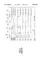
- FIG. 15 shows the waveforms of drive voltages and operation of switches in the driver circuit shown in FIG. 12.
- the waveforms shown in FIG. 15 correspond to the driving sequence shown in FIG. 7.
- the sustaining pulses 31 have a pulse duration of 2 us, a period of 6 us, and a voltage of -160 V.
- the scanning pulses 32 have the same pulse duration, period, and voltage as those of the sustaining pulses 31.
- the scanning pulses 33 have a pulse duration of 3 us and a voltage of -180 V.
- the data pulses 34 have the same pulse duration as that of the scanning pulses 33, and a voltage of +70 V.
- the preliminary discharge pulses 36 have a pulse duration of 10 us and a voltage of -300 V.
- the preliminary discharge extinguishing pulses 37 have a pulse duration of 1 us and a voltage of -90 V.
- the sustaining pulses 41 have a pulse duration of 20 us and a voltage of -160 V. Extinguishing pulses are not employed in FIG. 15, but may be employed.
- the preliminary discharge pulses 36, the sustaining pulses 41, and the sustaining pulses 31 are applied to the electrodes CA, CB, CC.
- the sustaining pulses 31 are applied commonly to the entire screen of the plasma display panel 10.
- FIG. 12 which shows the driver circuit that operates according to the driving sequence shown in FIG. 14 with the drive voltages shown in FIG.
- the switch SW1 is turned on connecting the electrodes CA, CB, CC to the ground potential in periods except while the preliminary discharge pulses 36, the sustaining pulses 41, and the sustaining pulses 31 are being applied
- the switch SW2 is turned on holding the electrodes CA, CB, CC at a common sustaining pulse potential in periods while the sustaining pulses 31 are being applied
- the switch SW3 is turned on connecting the scanning electrodes SC11, SCl2, . . . , SC1m, SC21, SC22, . . . , SC2m, and SC31, SC32, . . .
- FIG. 16 shows a driver circuit for a plasma display panel according to a second embodiment of the present invention, which includes a pair of charge collecting circuits.
- the plasma display panel according to the second embodiment employs charge collecting circuits as disclosed in Japanese patent application No. 41536/95 for collecting energy to charge and discharge the static capacity of the plasma display panel for thereby effectively reducing its power requirement.
- Those parts shown in FIG. 16 which are identical to those shown in FIG. 12 are denoted by identical reference characters and will not be described in detail below.
- the driver circuit additionally has a switch SW10 having an end connected to the cathodes of the diodes DD10 ⁇ DD12 and an opposite end to an end of a charge-collecting coil L1 whose opposite end is connected to the anodes of the diodes DD1 ⁇ DD3, and a switch SW11 having an end connected to the anodes of the diodes DD7 ⁇ DD9 and an opposite end to an end of a charge-collecting coil L2 whose opposite end is connected to the cathodes of the diodes DD ⁇ DD6.
- the switch SW10 and the coil L1 jointly make up a charge collecting circuit
- the switch SW11 and the coil L2 also jointly make up a charge collecting circuit.
- Other details of the driver circuit shown in FIG. 16 are the same as those of the driver circuit shown in FIG. 12.
- the waveforms of drive voltages and operation of the switches of the driver circuit shown in FIG. 16 will be described below with reference to FIG. 17.
- the drive voltages and operation of the switches SW1 ⁇ SW4 shown in FIG. 17 are the same as those shown in FIG. 15.
- the switch SW11 is turned on at a positive-going edge of the first sustaining pulse 32, and successively turned on at respective positive-going edges of the successive sustaining pulses 32.
- the switch SW10 remains turned off as the sustaining pulses are stopped.
- the switch SW10 is turned on at a positive-going edge of the first sustaining pulse 31, and successively turned on at respective positive-going edges of the successive sustaining pulses 31. At the final sustaining pulse 31, the sustaining pulses are not yet stopped, but lead to the final sustaining pulse 32. The switch SW10 is turned on at a positive-going edge of the final sustaining pulse 31.
- FIG. 18 shows at enlarged scale a portion of the waveforms shown in FIG. 17 where sustaining pulses are successively generated in the period D5.
- FIG. 18 also shows the waveforms of currents flowing through the coils L1, L2, the currents being positive when flowing in the direction indicated by the arrows in FIG. 16.
- the sustaining electrodes 13a are kept at a zero potential and the scanning electrodes 13b are kept at a negative sustaining pulse potential prior to a time t1.
- the switches SW1, SW4 are turned off, and only the switch SW11 is turned on.
- a current now flows from the sustaining electrodes 13a through the diodes DD4 ⁇ DD6, the coil L2, the switch SW11, the diodes DD7 ⁇ DD9, and the terminals TM3 of the scanning pulse generators 2 to the scanning electrodes 13b, charging the sustaining electrodes 13a and the scanning electrodes 13b to an opposite polarity.
- the current flows due to resonance between the coil L2 and the static capacity of the plasma display panel 10.
- the potential of the sustaining electrodes 13a decreases, and the potential of the scanning electrodes 13b increases.
- the switch SW11 is turned off, and the switches SW2, SW3 are turned on, whereupon the sustaining electrodes 13a are connected to the negative sustaining pulse potential and the scanning electrodes 13b are connected to the zero potential.
- the switches SW2, SW3 are turned off, and only the switch SW10 is turned on.
- a resonant current now flows from the scanning electrodes 13b through the terminals TM2 of the scanning pulse generators 2, the diodes DD11 ⁇ DD12, the switch SW10, the coil L1, and the diodes DD1 ⁇ DD3 to the sustaining electrodes 13a, charging the sustaining electrodes 13a and the scanning electrodes 13b to an opposite polarity.
- the potential of the sustaining electrodes 13a increases, and the potential of the scanning electrodes 13b decreases.
- the switch SW10 is turned off, and the switches SW1, SW4 are turned on, whereupon the sustaining electrodes 13a are connected to the zero potential and the scanning electrodes 13b are connected to a sustaining pulse potential.
- the added charge collecting circuit effectively collects energy to charge and discharge the static capacity of the plasma display panel for thereby saving electric power to operate the plasma display panel.
- the switch SW11 has been described as being turned off at the time t2 when the resonant current falls to zero. Actually, however, since the resonant current tending to flow continuously through the coil L2 after the time t2 is blocked by the diodes DD4 ⁇ DD6 or the diodes DD7 ⁇ DD9, the switch SW11 may be turned off anytime between the times t2, t3. Likewise, the switch SW10 may be turned off anytime between the times t4, t5.
- the switching elements used in the drive circuits according to the above embodiments may comprise a field-effect transistor (FET) which can turn on and off a large current at a high speed, and also a bipolar transistor, a thyristor, an IGBT, or the like insofar as it has an appropriate operation speed and a current supply capability.
- FET field-effect transistor
- the principles of the present invention are applicable to a plasma display panel free of sustaining electrodes, i.e., a facing-discharge-type plasma display panel.
Abstract
Description
Claims (4)
Applications Claiming Priority (2)
| Application Number | Priority Date | Filing Date | Title |
|---|---|---|---|
| JP8-307951 | 1996-11-19 | ||
| JP8307951A JP2874671B2 (en) | 1996-11-19 | 1996-11-19 | Drive circuit for plasma display panel |
Publications (1)
| Publication Number | Publication Date |
|---|---|
| US6057815A true US6057815A (en) | 2000-05-02 |
Family
ID=17975141
Family Applications (1)
| Application Number | Title | Priority Date | Filing Date |
|---|---|---|---|
| US08/974,345 Expired - Fee Related US6057815A (en) | 1996-11-19 | 1997-11-19 | Driver circuit for AC-memory plasma display panel |
Country Status (2)
| Country | Link |
|---|---|
| US (1) | US6057815A (en) |
| JP (1) | JP2874671B2 (en) |
Cited By (17)
| Publication number | Priority date | Publication date | Assignee | Title |
|---|---|---|---|---|
| US6232935B1 (en) * | 1997-09-01 | 2001-05-15 | Samsung Sdi Co., Ltd. | Plasma display panel and method for driving the same |
| EP1172787A1 (en) * | 2000-07-13 | 2002-01-16 | Deutsche Thomson-Brandt Gmbh | Gradation control of a matrix display |
| EP1172790A1 (en) * | 2000-07-13 | 2002-01-16 | Deutsche Thomson-Brandt Gmbh | Gradation control of a matrix display |
| US6362800B1 (en) * | 1998-01-17 | 2002-03-26 | Lg Electronics Inc. | Method and apparatus for driving plasma display panel |
| US6373451B1 (en) * | 1999-03-02 | 2002-04-16 | Samsung Sdi Co., Ltd. | Method for driving AC plasma display panel |
| US20020154075A1 (en) * | 2001-04-18 | 2002-10-24 | Nec Corporation | Plasma display unit and substrate used in the same |
| EP1256925A2 (en) * | 2001-05-08 | 2002-11-13 | Pioneer Corporation | Display panel drive apparatus |
| WO2003001492A1 (en) * | 2001-06-20 | 2003-01-03 | Matsushita Electric Industrial Co., Ltd. | Plasma display panel display and its drive method |
| EP1310936A1 (en) * | 2001-11-09 | 2003-05-14 | Matsushita Electric Industrial Co., Ltd. (MEI) | Energy recovery circuit for driving a capacitive load |
| US6741238B2 (en) * | 2000-02-08 | 2004-05-25 | Hyundai Electronics Industries Co., Ltd. | Power saving circuit for display panel |
| EP1571641A1 (en) * | 2002-12-13 | 2005-09-07 | Matsushita Electric Industrial Co., Ltd. | Plasma display panel drive method |
| US20050264477A1 (en) * | 2004-05-31 | 2005-12-01 | Gab-Sick Kim | Plasma display panel driving method |
| US20050280608A1 (en) * | 2004-06-18 | 2005-12-22 | Gab-Sick Kim | Driving method of plasma display panel |
| US20070109290A1 (en) * | 2005-11-15 | 2007-05-17 | Lg Electronics Inc. | Display device having plurality of power supplies and method for controlling the same |
| CN1326102C (en) * | 2001-10-15 | 2007-07-11 | 三星Sdi株式会社 | Apparatus and method for driving plasma display panel |
| CN100369089C (en) * | 2004-11-26 | 2008-02-13 | 友达光电股份有限公司 | Plasma displaying panel and driving method for plasma displaying panel |
| US20080150835A1 (en) * | 2006-12-20 | 2008-06-26 | Lg Electronics Inc. | Plasma display apparatus and driving method thereof |
Families Citing this family (7)
| Publication number | Priority date | Publication date | Assignee | Title |
|---|---|---|---|---|
| JP2000047636A (en) | 1998-07-30 | 2000-02-18 | Matsushita Electric Ind Co Ltd | Ac type plasma display device |
| JP3603712B2 (en) | 1999-12-24 | 2004-12-22 | 日本電気株式会社 | Driving apparatus for plasma display panel and driving method thereof |
| JP2001265281A (en) * | 2000-03-17 | 2001-09-28 | Matsushita Electric Ind Co Ltd | Display device and its driving method |
| JP3665956B2 (en) | 2000-03-23 | 2005-06-29 | パイオニアプラズマディスプレイ株式会社 | Plasma display panel drive circuit |
| CN1623177A (en) * | 2001-05-30 | 2005-06-01 | 皇家菲利浦电子有限公司 | Method and apparatus for driving a display panel |
| KR100400466B1 (en) * | 2001-06-19 | 2003-10-01 | 엘지전자 주식회사 | Driving Device of Plasma Display Panel |
| JP2005037604A (en) * | 2003-07-18 | 2005-02-10 | Matsushita Electric Ind Co Ltd | Plasma display device |
Citations (7)
| Publication number | Priority date | Publication date | Assignee | Title |
|---|---|---|---|---|
| JPH01233492A (en) * | 1988-03-15 | 1989-09-19 | Fujitsu Ltd | Method for driving planar display device |
| US5420602A (en) * | 1991-12-20 | 1995-05-30 | Fujitsu Limited | Method and apparatus for driving display panel |
| JPH07191627A (en) * | 1993-12-27 | 1995-07-28 | Nec Corp | Discharging method of plasma display panel |
| US5670974A (en) * | 1994-09-28 | 1997-09-23 | Nec Corporation | Energy recovery driver for a dot matrix AC plasma display panel with a parallel resonant circuit allowing power reduction |
| US5684499A (en) * | 1993-11-29 | 1997-11-04 | Nec Corporation | Method of driving plasma display panel having improved operational margin |
| US5717437A (en) * | 1994-12-07 | 1998-02-10 | Nec Corporation | Matrix display panel driver with charge collection circuit used to collect charge from the capacitive loads of the display |
| US5828353A (en) * | 1996-05-31 | 1998-10-27 | Fujitsu Limited | Drive unit for planar display |
-
1996
- 1996-11-19 JP JP8307951A patent/JP2874671B2/en not_active Expired - Fee Related
-
1997
- 1997-11-19 US US08/974,345 patent/US6057815A/en not_active Expired - Fee Related
Patent Citations (7)
| Publication number | Priority date | Publication date | Assignee | Title |
|---|---|---|---|---|
| JPH01233492A (en) * | 1988-03-15 | 1989-09-19 | Fujitsu Ltd | Method for driving planar display device |
| US5420602A (en) * | 1991-12-20 | 1995-05-30 | Fujitsu Limited | Method and apparatus for driving display panel |
| US5684499A (en) * | 1993-11-29 | 1997-11-04 | Nec Corporation | Method of driving plasma display panel having improved operational margin |
| JPH07191627A (en) * | 1993-12-27 | 1995-07-28 | Nec Corp | Discharging method of plasma display panel |
| US5670974A (en) * | 1994-09-28 | 1997-09-23 | Nec Corporation | Energy recovery driver for a dot matrix AC plasma display panel with a parallel resonant circuit allowing power reduction |
| US5717437A (en) * | 1994-12-07 | 1998-02-10 | Nec Corporation | Matrix display panel driver with charge collection circuit used to collect charge from the capacitive loads of the display |
| US5828353A (en) * | 1996-05-31 | 1998-10-27 | Fujitsu Limited | Drive unit for planar display |
Non-Patent Citations (2)
| Title |
|---|
| Akira Otsuka, "Large Size ac-type Color Plasma Display", Display and Imaging, vol., 4, 1996, pp. 67-73. |
| Akira Otsuka, Large Size ac type Color Plasma Display , Display and Imaging , vol., 4, 1996, pp. 67 73. * |
Cited By (26)
| Publication number | Priority date | Publication date | Assignee | Title |
|---|---|---|---|---|
| US6232935B1 (en) * | 1997-09-01 | 2001-05-15 | Samsung Sdi Co., Ltd. | Plasma display panel and method for driving the same |
| US6362800B1 (en) * | 1998-01-17 | 2002-03-26 | Lg Electronics Inc. | Method and apparatus for driving plasma display panel |
| US6373451B1 (en) * | 1999-03-02 | 2002-04-16 | Samsung Sdi Co., Ltd. | Method for driving AC plasma display panel |
| US6741238B2 (en) * | 2000-02-08 | 2004-05-25 | Hyundai Electronics Industries Co., Ltd. | Power saving circuit for display panel |
| EP1172787A1 (en) * | 2000-07-13 | 2002-01-16 | Deutsche Thomson-Brandt Gmbh | Gradation control of a matrix display |
| EP1172790A1 (en) * | 2000-07-13 | 2002-01-16 | Deutsche Thomson-Brandt Gmbh | Gradation control of a matrix display |
| US6753832B2 (en) * | 2000-07-13 | 2004-06-22 | Thomson Licensing S.A. | Method for controlling light emission of a matrix display in a display period and apparatus for carrying out the method |
| US20020154075A1 (en) * | 2001-04-18 | 2002-10-24 | Nec Corporation | Plasma display unit and substrate used in the same |
| EP1256925A3 (en) * | 2001-05-08 | 2004-08-04 | Pioneer Corporation | Display panel drive apparatus |
| US7133006B2 (en) | 2001-05-08 | 2006-11-07 | Pioneer Corporation | Display panel drive apparatus |
| US20020167381A1 (en) * | 2001-05-08 | 2002-11-14 | Pioneer Corporation | Display panel drive apparatus |
| EP1256925A2 (en) * | 2001-05-08 | 2002-11-13 | Pioneer Corporation | Display panel drive apparatus |
| WO2003001492A1 (en) * | 2001-06-20 | 2003-01-03 | Matsushita Electric Industrial Co., Ltd. | Plasma display panel display and its drive method |
| US20040239592A1 (en) * | 2001-06-20 | 2004-12-02 | Taku Okada | Plasma display panel display and its drive method |
| CN1326102C (en) * | 2001-10-15 | 2007-07-11 | 三星Sdi株式会社 | Apparatus and method for driving plasma display panel |
| US6850213B2 (en) | 2001-11-09 | 2005-02-01 | Matsushita Electric Industrial Co., Ltd. | Energy recovery circuit for driving a capacitive load |
| EP1310936A1 (en) * | 2001-11-09 | 2003-05-14 | Matsushita Electric Industrial Co., Ltd. (MEI) | Energy recovery circuit for driving a capacitive load |
| EP1571641A1 (en) * | 2002-12-13 | 2005-09-07 | Matsushita Electric Industrial Co., Ltd. | Plasma display panel drive method |
| EP1571641A4 (en) * | 2002-12-13 | 2009-04-29 | Panasonic Corp | Plasma display panel drive method |
| US20050264477A1 (en) * | 2004-05-31 | 2005-12-01 | Gab-Sick Kim | Plasma display panel driving method |
| EP1605429A1 (en) * | 2004-05-31 | 2005-12-14 | Samsung SDI Co., Ltd. | Plasma display panel driving method |
| US20050280608A1 (en) * | 2004-06-18 | 2005-12-22 | Gab-Sick Kim | Driving method of plasma display panel |
| CN100369089C (en) * | 2004-11-26 | 2008-02-13 | 友达光电股份有限公司 | Plasma displaying panel and driving method for plasma displaying panel |
| US20070109290A1 (en) * | 2005-11-15 | 2007-05-17 | Lg Electronics Inc. | Display device having plurality of power supplies and method for controlling the same |
| US7817147B2 (en) * | 2005-11-15 | 2010-10-19 | Lg Electronics Inc. | Display device having plurality of power supplies and method for controlling the same |
| US20080150835A1 (en) * | 2006-12-20 | 2008-06-26 | Lg Electronics Inc. | Plasma display apparatus and driving method thereof |
Also Published As
| Publication number | Publication date |
|---|---|
| JPH10149131A (en) | 1998-06-02 |
| JP2874671B2 (en) | 1999-03-24 |
Similar Documents
| Publication | Publication Date | Title |
|---|---|---|
| US6057815A (en) | Driver circuit for AC-memory plasma display panel | |
| KR100354286B1 (en) | Driver for display panel | |
| US6738033B1 (en) | High resolution and high luminance plasma display panel and drive method for the same | |
| US6340960B1 (en) | Circuit and method for driving plasma display panel | |
| TWI291190B (en) | Display device and plasma display apparatus | |
| JPH10333637A (en) | Plasma discharge display element and its driving method | |
| US6127992A (en) | Method of driving electric discharge panel | |
| JP2000267625A (en) | Gas discharge panel display device and gas discharge panel driving method | |
| KR100639540B1 (en) | Plasma display panel driving method, plasma display panel driver circuit, and plasma display device | |
| JP2907167B2 (en) | Color plasma display panel | |
| JPH1092323A (en) | Display panel, and panel type display device | |
| US7710372B2 (en) | PDP data driver, PDP driving method, plasma display device, and control method for the same | |
| US5315213A (en) | Structure and driving method of a plasma display panel | |
| US20070139307A1 (en) | Apparatus and method for driving display panel | |
| US7408532B2 (en) | Plasma display device and drive method for use in plasma display device | |
| US5966107A (en) | Method for driving a plasma display panel | |
| US7009583B2 (en) | Display panel with sustain electrodes | |
| US8325110B2 (en) | Power supply and driver for plasma display panel | |
| US6472826B2 (en) | Method of driving plasma display panel and a plasma display device using the method | |
| KR100251148B1 (en) | Method for driving three electrodes surface discharge plasma display panel | |
| KR100426574B1 (en) | Method for driving ac pdp using local scanning method | |
| KR20020029490A (en) | Method for driving a plasma display panel | |
| JP2917184B2 (en) | Matrix driven display device and display method | |
| US20060262042A1 (en) | Method of driving plasma display panel (PDP) | |
| US20050156822A1 (en) | Panel driving apparatus |
Legal Events
| Date | Code | Title | Description |
|---|---|---|---|
| AS | Assignment |
Owner name: NEC CORPORATION, JAPAN Free format text: ASSIGNMENT OF ASSIGNORS INTEREST;ASSIGNOR:SANO, YOSHIO;REEL/FRAME:008832/0809 Effective date: 19971110 |
|
| FEPP | Fee payment procedure |
Free format text: PAYOR NUMBER ASSIGNED (ORIGINAL EVENT CODE: ASPN); ENTITY STATUS OF PATENT OWNER: LARGE ENTITY |
|
| FPAY | Fee payment |
Year of fee payment: 4 |
|
| AS | Assignment |
Owner name: NEC PLASMA DISPLAY CORPORATION, JAPAN Free format text: ASSIGNMENT OF ASSIGNORS INTEREST;ASSIGNOR:NEC CORPORATION;REEL/FRAME:015931/0301 Effective date: 20040930 |
|
| AS | Assignment |
Owner name: PIONEER PLASMA DISPLAY CORPORATION, JAPAN Free format text: ASSIGNMENT OF ASSIGNORS INTEREST;ASSIGNOR:NEC PLASMA DISPLAY CORPORATION;REEL/FRAME:016038/0801 Effective date: 20040930 |
|
| AS | Assignment |
Owner name: PIONEER CORPORATION,JAPAN Free format text: ASSIGNMENT OF ASSIGNORS INTEREST;ASSIGNOR:PIONEER PLASMA DISPLAY CORPORATION;REEL/FRAME:016334/0922 Effective date: 20050531 Owner name: PIONEER CORPORATION, JAPAN Free format text: ASSIGNMENT OF ASSIGNORS INTEREST;ASSIGNOR:PIONEER PLASMA DISPLAY CORPORATION;REEL/FRAME:016334/0922 Effective date: 20050531 |
|
| REMI | Maintenance fee reminder mailed | ||
| LAPS | Lapse for failure to pay maintenance fees | ||
| STCH | Information on status: patent discontinuation |
Free format text: PATENT EXPIRED DUE TO NONPAYMENT OF MAINTENANCE FEES UNDER 37 CFR 1.362 |
|
| FP | Lapsed due to failure to pay maintenance fee |
Effective date: 20080502 |