US6051291A - Heat reflective sleeve with insulating air pocket - Google Patents
Heat reflective sleeve with insulating air pocket Download PDFInfo
- Publication number
- US6051291A US6051291A US09/106,296 US10629698A US6051291A US 6051291 A US6051291 A US 6051291A US 10629698 A US10629698 A US 10629698A US 6051291 A US6051291 A US 6051291A
- Authority
- US
- United States
- Prior art keywords
- protective sleeve
- air pocket
- heat protective
- sleeve according
- flexible
- Prior art date
- Legal status (The legal status is an assumption and is not a legal conclusion. Google has not performed a legal analysis and makes no representation as to the accuracy of the status listed.)
- Expired - Fee Related
Links
- 230000001681 protective effect Effects 0.000 claims abstract description 31
- 239000000463 material Substances 0.000 claims abstract 5
- 239000000758 substrate Substances 0.000 claims description 12
- 239000002184 metal Substances 0.000 claims description 8
- 239000011888 foil Substances 0.000 claims description 7
- 239000000853 adhesive Substances 0.000 claims description 6
- 230000001070 adhesive effect Effects 0.000 claims description 6
- 239000011810 insulating material Substances 0.000 claims description 6
- 239000003365 glass fiber Substances 0.000 claims description 5
- 229920000728 polyester Polymers 0.000 claims description 4
- 230000002441 reversible effect Effects 0.000 claims description 4
- 239000004753 textile Substances 0.000 claims 4
- 239000010410 layer Substances 0.000 description 16
- 239000000446 fuel Substances 0.000 description 5
- 230000004888 barrier function Effects 0.000 description 3
- 230000005855 radiation Effects 0.000 description 3
- 229910000831 Steel Inorganic materials 0.000 description 2
- 239000012790 adhesive layer Substances 0.000 description 2
- 230000000903 blocking effect Effects 0.000 description 2
- 239000012530 fluid Substances 0.000 description 2
- 238000009413 insulation Methods 0.000 description 2
- 239000010959 steel Substances 0.000 description 2
- 230000002411 adverse Effects 0.000 description 1
- 238000005452 bending Methods 0.000 description 1
- 239000011230 binding agent Substances 0.000 description 1
- 230000003197 catalytic effect Effects 0.000 description 1
- 238000002485 combustion reaction Methods 0.000 description 1
- 230000000694 effects Effects 0.000 description 1
- 238000010292 electrical insulation Methods 0.000 description 1
- 238000009429 electrical wiring Methods 0.000 description 1
- 239000012210 heat-resistant fiber Substances 0.000 description 1
- 230000001788 irregular Effects 0.000 description 1
- 230000007774 longterm Effects 0.000 description 1
- 239000011104 metalized film Substances 0.000 description 1
- 238000000926 separation method Methods 0.000 description 1
Images


Classifications
-
- F—MECHANICAL ENGINEERING; LIGHTING; HEATING; WEAPONS; BLASTING
- F16—ENGINEERING ELEMENTS AND UNITS; GENERAL MEASURES FOR PRODUCING AND MAINTAINING EFFECTIVE FUNCTIONING OF MACHINES OR INSTALLATIONS; THERMAL INSULATION IN GENERAL
- F16L—PIPES; JOINTS OR FITTINGS FOR PIPES; SUPPORTS FOR PIPES, CABLES OR PROTECTIVE TUBING; MEANS FOR THERMAL INSULATION IN GENERAL
- F16L59/00—Thermal insulation in general
- F16L59/02—Shape or form of insulating materials, with or without coverings integral with the insulating materials
-
- F—MECHANICAL ENGINEERING; LIGHTING; HEATING; WEAPONS; BLASTING
- F16—ENGINEERING ELEMENTS AND UNITS; GENERAL MEASURES FOR PRODUCING AND MAINTAINING EFFECTIVE FUNCTIONING OF MACHINES OR INSTALLATIONS; THERMAL INSULATION IN GENERAL
- F16L—PIPES; JOINTS OR FITTINGS FOR PIPES; SUPPORTS FOR PIPES, CABLES OR PROTECTIVE TUBING; MEANS FOR THERMAL INSULATION IN GENERAL
- F16L59/00—Thermal insulation in general
- F16L59/08—Means for preventing radiation, e.g. with metal foil
-
- B—PERFORMING OPERATIONS; TRANSPORTING
- B60—VEHICLES IN GENERAL
- B60T—VEHICLE BRAKE CONTROL SYSTEMS OR PARTS THEREOF; BRAKE CONTROL SYSTEMS OR PARTS THEREOF, IN GENERAL; ARRANGEMENT OF BRAKING ELEMENTS ON VEHICLES IN GENERAL; PORTABLE DEVICES FOR PREVENTING UNWANTED MOVEMENT OF VEHICLES; VEHICLE MODIFICATIONS TO FACILITATE COOLING OF BRAKES
- B60T17/00—Component parts, details, or accessories of power brake systems not covered by groups B60T8/00, B60T13/00 or B60T15/00, or presenting other characteristic features
- B60T17/18—Safety devices; Monitoring
-
- F—MECHANICAL ENGINEERING; LIGHTING; HEATING; WEAPONS; BLASTING
- F16—ENGINEERING ELEMENTS AND UNITS; GENERAL MEASURES FOR PRODUCING AND MAINTAINING EFFECTIVE FUNCTIONING OF MACHINES OR INSTALLATIONS; THERMAL INSULATION IN GENERAL
- F16L—PIPES; JOINTS OR FITTINGS FOR PIPES; SUPPORTS FOR PIPES, CABLES OR PROTECTIVE TUBING; MEANS FOR THERMAL INSULATION IN GENERAL
- F16L59/00—Thermal insulation in general
- F16L59/06—Arrangements using an air layer or vacuum
-
- B—PERFORMING OPERATIONS; TRANSPORTING
- B60—VEHICLES IN GENERAL
- B60K—ARRANGEMENT OR MOUNTING OF PROPULSION UNITS OR OF TRANSMISSIONS IN VEHICLES; ARRANGEMENT OR MOUNTING OF PLURAL DIVERSE PRIME-MOVERS IN VEHICLES; AUXILIARY DRIVES FOR VEHICLES; INSTRUMENTATION OR DASHBOARDS FOR VEHICLES; ARRANGEMENTS IN CONNECTION WITH COOLING, AIR INTAKE, GAS EXHAUST OR FUEL SUPPLY OF PROPULSION UNITS IN VEHICLES
- B60K13/00—Arrangement in connection with combustion air intake or gas exhaust of propulsion units
- B60K13/04—Arrangement in connection with combustion air intake or gas exhaust of propulsion units concerning exhaust
-
- B—PERFORMING OPERATIONS; TRANSPORTING
- B60—VEHICLES IN GENERAL
- B60K—ARRANGEMENT OR MOUNTING OF PROPULSION UNITS OR OF TRANSMISSIONS IN VEHICLES; ARRANGEMENT OR MOUNTING OF PLURAL DIVERSE PRIME-MOVERS IN VEHICLES; AUXILIARY DRIVES FOR VEHICLES; INSTRUMENTATION OR DASHBOARDS FOR VEHICLES; ARRANGEMENTS IN CONNECTION WITH COOLING, AIR INTAKE, GAS EXHAUST OR FUEL SUPPLY OF PROPULSION UNITS IN VEHICLES
- B60K15/00—Arrangement in connection with fuel supply of combustion engines or other fuel consuming energy converters, e.g. fuel cells; Mounting or construction of fuel tanks
- B60K15/01—Arrangement of fuel conduits
-
- Y—GENERAL TAGGING OF NEW TECHNOLOGICAL DEVELOPMENTS; GENERAL TAGGING OF CROSS-SECTIONAL TECHNOLOGIES SPANNING OVER SEVERAL SECTIONS OF THE IPC; TECHNICAL SUBJECTS COVERED BY FORMER USPC CROSS-REFERENCE ART COLLECTIONS [XRACs] AND DIGESTS
- Y10—TECHNICAL SUBJECTS COVERED BY FORMER USPC
- Y10T—TECHNICAL SUBJECTS COVERED BY FORMER US CLASSIFICATION
- Y10T428/00—Stock material or miscellaneous articles
- Y10T428/13—Hollow or container type article [e.g., tube, vase, etc.]
- Y10T428/131—Glass, ceramic, or sintered, fused, fired, or calcined metal oxide or metal carbide containing [e.g., porcelain, brick, cement, etc.]
-
- Y—GENERAL TAGGING OF NEW TECHNOLOGICAL DEVELOPMENTS; GENERAL TAGGING OF CROSS-SECTIONAL TECHNOLOGIES SPANNING OVER SEVERAL SECTIONS OF THE IPC; TECHNICAL SUBJECTS COVERED BY FORMER USPC CROSS-REFERENCE ART COLLECTIONS [XRACs] AND DIGESTS
- Y10—TECHNICAL SUBJECTS COVERED BY FORMER USPC
- Y10T—TECHNICAL SUBJECTS COVERED BY FORMER US CLASSIFICATION
- Y10T428/00—Stock material or miscellaneous articles
- Y10T428/13—Hollow or container type article [e.g., tube, vase, etc.]
- Y10T428/1334—Nonself-supporting tubular film or bag [e.g., pouch, envelope, packet, etc.]
- Y10T428/1338—Elemental metal containing
-
- Y—GENERAL TAGGING OF NEW TECHNOLOGICAL DEVELOPMENTS; GENERAL TAGGING OF CROSS-SECTIONAL TECHNOLOGIES SPANNING OVER SEVERAL SECTIONS OF THE IPC; TECHNICAL SUBJECTS COVERED BY FORMER USPC CROSS-REFERENCE ART COLLECTIONS [XRACs] AND DIGESTS
- Y10—TECHNICAL SUBJECTS COVERED BY FORMER USPC
- Y10T—TECHNICAL SUBJECTS COVERED BY FORMER US CLASSIFICATION
- Y10T428/00—Stock material or miscellaneous articles
- Y10T428/13—Hollow or container type article [e.g., tube, vase, etc.]
- Y10T428/1352—Polymer or resin containing [i.e., natural or synthetic]
- Y10T428/1355—Elemental metal containing [e.g., substrate, foil, film, coating, etc.]
-
- Y—GENERAL TAGGING OF NEW TECHNOLOGICAL DEVELOPMENTS; GENERAL TAGGING OF CROSS-SECTIONAL TECHNOLOGIES SPANNING OVER SEVERAL SECTIONS OF THE IPC; TECHNICAL SUBJECTS COVERED BY FORMER USPC CROSS-REFERENCE ART COLLECTIONS [XRACs] AND DIGESTS
- Y10—TECHNICAL SUBJECTS COVERED BY FORMER USPC
- Y10T—TECHNICAL SUBJECTS COVERED BY FORMER US CLASSIFICATION
- Y10T428/00—Stock material or miscellaneous articles
- Y10T428/13—Hollow or container type article [e.g., tube, vase, etc.]
- Y10T428/1352—Polymer or resin containing [i.e., natural or synthetic]
- Y10T428/1362—Textile, fabric, cloth, or pile containing [e.g., web, net, woven, knitted, mesh, nonwoven, matted, etc.]
-
- Y—GENERAL TAGGING OF NEW TECHNOLOGICAL DEVELOPMENTS; GENERAL TAGGING OF CROSS-SECTIONAL TECHNOLOGIES SPANNING OVER SEVERAL SECTIONS OF THE IPC; TECHNICAL SUBJECTS COVERED BY FORMER USPC CROSS-REFERENCE ART COLLECTIONS [XRACs] AND DIGESTS
- Y10—TECHNICAL SUBJECTS COVERED BY FORMER USPC
- Y10T—TECHNICAL SUBJECTS COVERED BY FORMER US CLASSIFICATION
- Y10T428/00—Stock material or miscellaneous articles
- Y10T428/13—Hollow or container type article [e.g., tube, vase, etc.]
- Y10T428/1352—Polymer or resin containing [i.e., natural or synthetic]
- Y10T428/1369—Fiber or fibers wound around each other or into a self-sustaining shape [e.g., yarn, braid, fibers shaped around a core, etc.]
-
- Y—GENERAL TAGGING OF NEW TECHNOLOGICAL DEVELOPMENTS; GENERAL TAGGING OF CROSS-SECTIONAL TECHNOLOGIES SPANNING OVER SEVERAL SECTIONS OF THE IPC; TECHNICAL SUBJECTS COVERED BY FORMER USPC CROSS-REFERENCE ART COLLECTIONS [XRACs] AND DIGESTS
- Y10—TECHNICAL SUBJECTS COVERED BY FORMER USPC
- Y10T—TECHNICAL SUBJECTS COVERED BY FORMER US CLASSIFICATION
- Y10T428/00—Stock material or miscellaneous articles
- Y10T428/13—Hollow or container type article [e.g., tube, vase, etc.]
- Y10T428/1352—Polymer or resin containing [i.e., natural or synthetic]
- Y10T428/1372—Randomly noninterengaged or randomly contacting fibers, filaments, particles, or flakes
-
- Y—GENERAL TAGGING OF NEW TECHNOLOGICAL DEVELOPMENTS; GENERAL TAGGING OF CROSS-SECTIONAL TECHNOLOGIES SPANNING OVER SEVERAL SECTIONS OF THE IPC; TECHNICAL SUBJECTS COVERED BY FORMER USPC CROSS-REFERENCE ART COLLECTIONS [XRACs] AND DIGESTS
- Y10—TECHNICAL SUBJECTS COVERED BY FORMER USPC
- Y10T—TECHNICAL SUBJECTS COVERED BY FORMER US CLASSIFICATION
- Y10T428/00—Stock material or miscellaneous articles
- Y10T428/13—Hollow or container type article [e.g., tube, vase, etc.]
- Y10T428/1352—Polymer or resin containing [i.e., natural or synthetic]
- Y10T428/139—Open-ended, self-supporting conduit, cylinder, or tube-type article
- Y10T428/1393—Multilayer [continuous layer]
-
- Y—GENERAL TAGGING OF NEW TECHNOLOGICAL DEVELOPMENTS; GENERAL TAGGING OF CROSS-SECTIONAL TECHNOLOGIES SPANNING OVER SEVERAL SECTIONS OF THE IPC; TECHNICAL SUBJECTS COVERED BY FORMER USPC CROSS-REFERENCE ART COLLECTIONS [XRACs] AND DIGESTS
- Y10—TECHNICAL SUBJECTS COVERED BY FORMER USPC
- Y10T—TECHNICAL SUBJECTS COVERED BY FORMER US CLASSIFICATION
- Y10T428/00—Stock material or miscellaneous articles
- Y10T428/26—Web or sheet containing structurally defined element or component, the element or component having a specified physical dimension
Definitions
- This invention relates to reflective sleeving for thermal insulation of elongated items and especially to insulative sleeving for use, for example, in automotive, train and aircraft applications.
- Vehicles such as automobiles, trucks, busses, trains and aircraft typically employ internal combustion engines which produce significant heat.
- Components of an engine such as the exhaust manifold, catalytic converter and exhaust pipe, can achieve temperatures of several hundred degrees during the normal course of engine operation.
- These hot components must often be placed in proximity to other components, such as brake lines, electrical wiring or fuel lines, which must remain cool for long-term, effective operation.
- brake lines electrical wiring or fuel lines
- the electrical insulation could melt and/or ignite, causing an engine fire and an electrical short circuit.
- a fuel line is heated sufficiently by an adjacent engine component, gasoline in the line will vaporize leading to a complete or partial interruption of fuel flow to the engine. This is known as vapor lock, and under extreme conditions of vapor lock, the engine will stop or will not start.
- the invention comprises a heat protective sleeve for the protection of elongated components or substrates.
- the sleeve comprises a first flexible sheet of a thermally insulating material.
- the first sheet has two oppositely disposed edge portions which are placed in overlapping relationship to form a tubular protective wrap or covering around an elongated component, such as a brake line, which is to be protected from a nearby hot component, such as an exhaust pipe.
- a second flexible sheet also made of a thermally insulating material, has oppositely disposed edge portions which are attached to the first flexible sheet inwardly from the first sheet's edge portions.
- the second sheet is attached to the first sheet along the second sheet's edge portions, allowing a portion of the second sheet to bow outwardly from the first sheet and form an air pocket between the sheets.
- a means for forming the air pocket is interposed between the sheets.
- the air pocket provides extra insulation and is typically positioned facing the hot component, interposed between it and the component to be insulated.
- the sheets are woven or knitted from insulative, heat-resistant fibers, such as polyester monofilaments or glass fibers. It is also preferred to provide a reflective layer on the outside surface of the sheets to block thermal radiation from the hot component. For maximum insulating effect, the reflective layer is located on both the outside of the second sheet, as well as on the outside of the first sheet, including that portion of the first sheet within the air pocket which lies beneath the second sheet.
- a metal foil on the order of 20 microns in thickness provides an effective thermal radiation barrier and yet remains sufficiently flexible to permit manual conformity to a tubular shape. Metalized films may also be employed in some applications.
- the air pocket forming means can be a wire form bent to define an open-framed, elongated volume, for example, a monofilament wire formed into a spiral or helical shape.
- the formed wire is positioned lengthwise along the sleeve within the pocket.
- the wire is sufficiently stiff so as to maintain its shape, keeping the first and second sheet separated to form the air pocket.
- the wire is also sufficiently flexible so as to conform to the component around which the sleeve is wrapped.
- the pocket forming means comprises a continuous monofilament member, similarly formed like conventional notebook binder wire, into a multiplicity of spaced apart reverse bends forming a multiplicity of crests and troughs.
- the continuous monofilament member is further bent in cross section into a C-shaped configuration which positions the crests and troughs at the terminal points of the C-shape.
- the continuous monofilament member defines an axially extending region with an opening on one side bordered by the crests and troughs. The crests and troughs are arranged against the first flexible sheet within the air pocket.
- FIG. 1 shows an isometric view of the reflective sleeve wrap with an insulating air pocket according to the invention, the wrap being shown in a flat configuration;
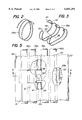
- FIG. 2 shows an isometric view of a detail from FIG. 1 on an enlarged scale
- FIG. 3 shows an isometric view of a detail from FIG. 1 on an enlarged scale
- FIG. 4 shows a cross sectional end view of the invention shown in a tubular-shaped configuration around an elongated member adjacent to a heat source;
- FIG. 5 shows a top plan view of the invention shown in FIG. 4 having cut-away portions showing internal details of the invention.
- FIG. 6 shows a cross-sectional view of the invention taken along lines 6--6 of FIG. 5.
- FIG. 1 shows a heat protective sleeve 10 according to the invention which comprises a first flexible sheet of thermally insulating material 12, providing a means formable into an elongated tubular shape.
- Flexible sheet 12 is woven or knitted, preferably from a polyester monofilament or from glass fiber yarns.
- Sheet 12 can be formed to any practical length as required to insulate elongated substrates or members, end 14 being shown with an irregular profile to indicate that sheet 12 extends beyond the length shown in FIG. 1.
- Sheet 12 has oppositely disposed edge portions 16 and 18 which are placed in overlapping relationship with respective portions of the sheet, as best shown in FIG. 4, to form the tubular protective covering.
- Each edge 16 and 18 has means for joining the edges to the sheet, described further below.
- a second flexible sheet 20 of thermally insulating material has oppositely disposed edge portions 22 and 24 which are attached to sheet 12 and spaced inwardly from edge portions 16 and 18. Edge portions 22 and 24 could be attached by stitching, but it is preferred to bond the edge portions to the sheet. A wide variety of adhesives may be employed, and heat-activated adhesives are preferred. Sheet 20 provides means for forming an air pocket 26 which runs lengthwise along sheet 12.
- a shaped monofilament wire illustrated as 28a or 28b, is disposed within air pocket 26.
- the wire comprises means for forming air pocket 26 and serves to space sheet 20 outwardly from sheet 12.
- the wire provides a flexible skeletal form enveloping an elongated volume and must be sufficiently stiff so as to maintain its shape and thereby the shape of the air pocket, but it must also be sufficiently flexible to allow sleeve 10 to conform to the shape of the elongated member around which the sleeve is wrapped.
- the combination of stiffness and flexibility is achieved by making the wire from a monofilament of a metal, such as steel, formed in a spiral shape, as seen at 28a in FIGS. 1 and 2.
- the steel spiral provides stiffness and elasticity in the radial direction to maintain the shape of air pocket 26, yet is flexible in bending to allow the sleeve to easily conform to a curvature along the length of the member being insulated.
- wire 28b is shown formed into a multiplicity of spaced apart reverse bends 30 forming a multiplicity of crests 32 and troughs 34.
- the crests and troughs are then further bent into a C-shaped configuration, positioning the crests and troughs adjacent to each other at the terminal points of the C-shape.
- Wire 28b thus, defines an axially extending region 36 with an opening 38 on one side bordered by the crests and troughs.
- the crests and troughs are arranged against the first flexible sheet 12 within air pocket 26, as best seen in FIG. 4 and in the cut-away view of FIG. 5.
- the preferred shape of wire 28b provides a radially rigid form which will maintain the shape of air pocket 26 yet provide longitudinal flexibility and allow the sleeve to conform to an elongated member or substrate.
- Opening 38 provides a discontinuity to the form of wire 28b which accepts a bulge 40 formed in sheet 12. The opening 38 helps orient wire 28b within air pocket 26 and prevents the wire from rotating within the air pocket and, thus, changing the shape of the pocket.
- sheets 12 and 20 each have means for reflecting radiant energy in the form of reflective cover layers 42 and 44, respectively (see FIG. 4).
- the reflective cover layers are positioned on the outside surfaces of the sheets and preferably comprise metal foil approximately 20 microns thick adhered to sheets 12 and 20.
- the foil is preferably bonded to the sheets with a heat-activated adhesive, although other adhesives are also suitable.
- sleeve 10 is wrapped around elongated members 46a-46d, which could be brake lines to be insulated by the sleeve.
- Members 46a-46d are secured in a cradle or clip 48, which is attached to a structure, such as a vehicle frame 50 seen in FIGS. 4 and 6.
- Clip 48 is attached to frame 50 by fastener means well known in the art, a rivet 52 being shown as an example.
- a heat source 54 for example, a portion of the exhaust system of the vehicle, is located near brake lines 46a-46d. To prevent the heat from the exhaust system portion 54 from adversely affecting the brake fluid within the brake lines, insulating sleeve 10 is disposed adjacent to the heat source surrounding the brake lines, as described below.
- sleeve 10 is preferably positioned on frame 50 adjacent to heat source 54 with the reflective layer 42 facing downwardly.
- Clip 48 is placed on top of sleeve 10 against flexible sheet 12 and fastened in place by rivet 52.
- Brake lines 46a-46d are positioned in clip 48, and a portion 12a of sheet 12 is folded over adjacent brake lines 46a and 46b bringing edge 18 toward sheet 12.
- Edge 18 has a plurality of loops 56 arranged along its length on loop tape, loops 56 being engagable with a plurality of hooks 58 formed on hook tape attached to sheet 12 intermediate edges 16 and 18 and extending lengthwise along sleeve 10. As seen in FIG.
- hooks 58 are not continuous, there being a gap 60 which allows clip 48 to continuously contact sheet 12.
- loops 56 are held securely, thus, holding edge 18 and a portion 12a of sheet 12 in the folded position.
- Sheet portion 12a has a cut-out 62 which fits around clip 48, allowing loops 56 on edge 18 to engage hooks 58 immediately adjacent to the clip without stretching or distorting sheet 12 around the clip.
- Adhesive layer 64 is covered with release paper 66 which is removed to exposed the adhesive just before the attachment is to be made.
- Folding sheet portion 12b positions air pocket 26 facing heat source 54.
- the air pocket lies between the two reflective layers 42 and 44. This combination of a reflective surface, followed by an air pocket, followed by a second reflective surface, is especially effective at blocking radiant energy from the heat source 54 incident on the sleeve.
- the outer most reflective layer 44 reflects the majority of the incident radiation. The outer layer will heat up, however, and conductively transfer a portion of the incident heat to underlying sheet 20. Sheet 20 will then radiate energy, which is reflected away from the inside of sleeve 10 by the inner reflective layer 42 on sheet 12.
- Air pocket 26 separates the reflective layers and inhibits conductive heat transfer between sheet 20 and sheet 12.
- Insulative sleeves according to the invention provide improved insulating performance over common insulating wraps which have a single non-conducting layer and a single reflective layer.
- the increased performance is maximized by adjusting the size of the air pocket so that it is sufficiently large to provide an effective heat barrier, yet is not oversized and consequently too close to the heat source, thereby providing undesired increased heat transfer to the elongated members.
- the sleeve according to the invention is flexible and compact and provides an efficient and economical means of insulating elongated substrates or members such as brake lines, fuel lines or electrical harnessing.
Abstract
Description
Claims (25)
Priority Applications (1)
| Application Number | Priority Date | Filing Date | Title |
|---|---|---|---|
| US09/106,296 US6051291A (en) | 1997-07-18 | 1998-06-29 | Heat reflective sleeve with insulating air pocket |
Applications Claiming Priority (2)
| Application Number | Priority Date | Filing Date | Title |
|---|---|---|---|
| US5312997P | 1997-07-18 | 1997-07-18 | |
| US09/106,296 US6051291A (en) | 1997-07-18 | 1998-06-29 | Heat reflective sleeve with insulating air pocket |
Publications (1)
| Publication Number | Publication Date |
|---|---|
| US6051291A true US6051291A (en) | 2000-04-18 |
Family
ID=21982123
Family Applications (1)
| Application Number | Title | Priority Date | Filing Date |
|---|---|---|---|
| US09/106,296 Expired - Fee Related US6051291A (en) | 1997-07-18 | 1998-06-29 | Heat reflective sleeve with insulating air pocket |
Country Status (12)
| Country | Link |
|---|---|
| US (1) | US6051291A (en) |
| EP (1) | EP0996841B1 (en) |
| JP (1) | JP2001510882A (en) |
| KR (1) | KR20010020584A (en) |
| AT (1) | ATE205587T1 (en) |
| BR (1) | BR9810912A (en) |
| CA (1) | CA2294863A1 (en) |
| DE (1) | DE69801666T2 (en) |
| ES (1) | ES2164429T3 (en) |
| HU (1) | HUP0004528A3 (en) |
| PL (1) | PL338080A1 (en) |
| WO (1) | WO1999004194A1 (en) |
Cited By (15)
| Publication number | Priority date | Publication date | Assignee | Title |
|---|---|---|---|---|
| WO2003013834A1 (en) * | 2001-08-06 | 2003-02-20 | Federal-Mogul Powertrain, Inc. | Thermally insulative sleeve |
| US20040022973A1 (en) * | 2002-08-02 | 2004-02-05 | Harry Bussey | Foamed laminated construction |
| US20040255435A1 (en) * | 2003-06-18 | 2004-12-23 | Suburban Machine Co., Inc. Dba Suburban Manufacturing, Inc. | Reusable hose bundling sleeve |
| US20070079884A1 (en) * | 2005-10-12 | 2007-04-12 | Arrowhead Products Corporation | Heat shrunk double wall, self-insulating, lightweight duct |
| US20070209729A1 (en) * | 2006-03-09 | 2007-09-13 | Arrowhead Products Corporation | Cable reinforcement for flexible ducts |
| US20070228226A1 (en) * | 2006-03-22 | 2007-10-04 | Michael Taillon | Adjustable spiral sleeve for protecting lines |
| US20070235100A1 (en) * | 2005-10-12 | 2007-10-11 | Arrowhead Products Corporation | Double walled, self-insulating, lightweight duct |
| US20080104804A1 (en) * | 2003-06-18 | 2008-05-08 | Suburban Machine Co., Inc. Dba Suburban Manufacturing, Inc. | Reusable hose bundling sleeve |
| US8505339B2 (en) | 2010-09-30 | 2013-08-13 | Federal-Mogul Powertrain, Inc. | Knit sleeve with knit barrier extension having a barrier therein and method of construction |
| US20160236564A1 (en) * | 2015-02-18 | 2016-08-18 | Toyota Motor Engineering & Manufacturing North America, Inc. | Protection of vehicle fluid conduits |
| US9633758B2 (en) | 2013-05-28 | 2017-04-25 | Federal-Mogul Powertrain, Inc. | Wrapped textile sleeve with bonded closure mechanism NAD method of construction thereof |
| US10711921B2 (en) | 2015-03-13 | 2020-07-14 | Bradley D Barger | Reusable hose bundling sleeve |
| WO2022125615A1 (en) * | 2020-12-08 | 2022-06-16 | Federal-Mogul Powertrain Llc | Protective, locatable sleeve and method of construction thereof |
| US20220290339A1 (en) * | 2019-09-10 | 2022-09-15 | Federal-Mogul Powertain LLC | Convolute woven sleeve and method of construction thereof |
| US11851010B2 (en) | 2020-12-08 | 2023-12-26 | Federal-Mogul Powertrain Llc | Protective, locatable sleeve and method of construction thereof |
Families Citing this family (7)
| Publication number | Priority date | Publication date | Assignee | Title |
|---|---|---|---|---|
| ATE261201T1 (en) * | 2000-04-27 | 2004-03-15 | Verta Ag | HEAT PROTECTION DEVICE, ESPECIALLY FOR LONG BODY |
| FR2832487B1 (en) | 2001-11-21 | 2004-02-13 | Fed Mogul Systems Prot Group | PROTECTIVE SHEATH FOR FLUID CIRCULATION TUBE |
| FR2838502B1 (en) * | 2002-04-12 | 2004-07-09 | Fed Mogul Systems Prot Group | SELF-CLOSING THERMAL PROTECTION SHEATH AND MANUFACTURING METHOD THEREOF |
| DE10300921A1 (en) | 2003-01-13 | 2004-07-22 | Verta Ag | Protective device for elongated objects |
| US7874184B2 (en) | 2007-08-23 | 2011-01-25 | Federal-Mogul Powertrain, Inc. | Thermal protection sleeve with knit thermal protection features and method of construction thereof |
| US7757517B2 (en) | 2007-08-23 | 2010-07-20 | Federal-Mogul Powertrain, Inc. | Protective sleeve with knitted opening and method on construction |
| JP6128031B2 (en) * | 2014-03-27 | 2017-05-17 | マツダ株式会社 | Engine exhaust pipe temperature control device |
Citations (7)
| Publication number | Priority date | Publication date | Assignee | Title |
|---|---|---|---|---|
| US4053667A (en) * | 1974-09-09 | 1977-10-11 | Lockheed Aircraft Corporation | Stiffened structural laminate and method of molding laminate with stiffener beads |
| US4064355A (en) * | 1976-11-08 | 1977-12-20 | Dayco Corporation | Polymeric flexible hose construction and method of making same |
| US4086937A (en) * | 1976-08-06 | 1978-05-02 | Hechler Iv Valentine | Dual hose |
| GB2004021A (en) * | 1977-09-08 | 1979-03-21 | Nederlandse Steenwolfabriek Nv | Insulating covering |
| EP0394117A1 (en) * | 1989-04-18 | 1990-10-24 | Société Industrielle de l'Ouest des produits Isolants" OUEST-ISOL" | Multi-layered coating and thermal insulating element with such a coating |
| US5538045A (en) * | 1995-02-14 | 1996-07-23 | Bentley-Harris Inc. | Protective sleeve with warp spacers |
| US5849379A (en) * | 1997-01-06 | 1998-12-15 | Bentley-Harris Inc. | Wrappable sleeve |
-
1998
- 1998-06-29 US US09/106,296 patent/US6051291A/en not_active Expired - Fee Related
- 1998-07-13 BR BR9810912-0A patent/BR9810912A/en active Search and Examination
- 1998-07-13 ES ES98929580T patent/ES2164429T3/en not_active Expired - Lifetime
- 1998-07-13 JP JP2000503363A patent/JP2001510882A/en active Pending
- 1998-07-13 EP EP98929580A patent/EP0996841B1/en not_active Expired - Lifetime
- 1998-07-13 PL PL98338080A patent/PL338080A1/en unknown
- 1998-07-13 DE DE69801666T patent/DE69801666T2/en not_active Expired - Fee Related
- 1998-07-13 CA CA002294863A patent/CA2294863A1/en not_active Abandoned
- 1998-07-13 AT AT98929580T patent/ATE205587T1/en active
- 1998-07-13 HU HU0004528A patent/HUP0004528A3/en unknown
- 1998-07-13 KR KR1019997012543A patent/KR20010020584A/en not_active Application Discontinuation
- 1998-07-13 WO PCT/IB1998/001063 patent/WO1999004194A1/en not_active Application Discontinuation
Patent Citations (7)
| Publication number | Priority date | Publication date | Assignee | Title |
|---|---|---|---|---|
| US4053667A (en) * | 1974-09-09 | 1977-10-11 | Lockheed Aircraft Corporation | Stiffened structural laminate and method of molding laminate with stiffener beads |
| US4086937A (en) * | 1976-08-06 | 1978-05-02 | Hechler Iv Valentine | Dual hose |
| US4064355A (en) * | 1976-11-08 | 1977-12-20 | Dayco Corporation | Polymeric flexible hose construction and method of making same |
| GB2004021A (en) * | 1977-09-08 | 1979-03-21 | Nederlandse Steenwolfabriek Nv | Insulating covering |
| EP0394117A1 (en) * | 1989-04-18 | 1990-10-24 | Société Industrielle de l'Ouest des produits Isolants" OUEST-ISOL" | Multi-layered coating and thermal insulating element with such a coating |
| US5538045A (en) * | 1995-02-14 | 1996-07-23 | Bentley-Harris Inc. | Protective sleeve with warp spacers |
| US5849379A (en) * | 1997-01-06 | 1998-12-15 | Bentley-Harris Inc. | Wrappable sleeve |
Cited By (22)
| Publication number | Priority date | Publication date | Assignee | Title |
|---|---|---|---|---|
| US6610928B2 (en) * | 2001-08-06 | 2003-08-26 | Federal-Mogul World Wide, Inc. | Thermally insulative sleeve |
| CN100396474C (en) * | 2001-08-06 | 2008-06-25 | 费德罗-莫格尔动力系公司 | Thermally insulative sleeve |
| WO2003013834A1 (en) * | 2001-08-06 | 2003-02-20 | Federal-Mogul Powertrain, Inc. | Thermally insulative sleeve |
| US20040022973A1 (en) * | 2002-08-02 | 2004-02-05 | Harry Bussey | Foamed laminated construction |
| US8127405B2 (en) | 2003-06-18 | 2012-03-06 | Suburban Machine Co., Inc. | Reusable hose bundling sleeve |
| US20040255435A1 (en) * | 2003-06-18 | 2004-12-23 | Suburban Machine Co., Inc. Dba Suburban Manufacturing, Inc. | Reusable hose bundling sleeve |
| US8691036B2 (en) | 2003-06-18 | 2014-04-08 | Suburban Machine Co., Inc. | Method of making a reusable hose bundling sleeve |
| US20080104804A1 (en) * | 2003-06-18 | 2008-05-08 | Suburban Machine Co., Inc. Dba Suburban Manufacturing, Inc. | Reusable hose bundling sleeve |
| US20070079884A1 (en) * | 2005-10-12 | 2007-04-12 | Arrowhead Products Corporation | Heat shrunk double wall, self-insulating, lightweight duct |
| US20070235100A1 (en) * | 2005-10-12 | 2007-10-11 | Arrowhead Products Corporation | Double walled, self-insulating, lightweight duct |
| US20070209729A1 (en) * | 2006-03-09 | 2007-09-13 | Arrowhead Products Corporation | Cable reinforcement for flexible ducts |
| US7895716B2 (en) | 2006-03-22 | 2011-03-01 | Taimi R&D Inc. | Adjustable spiral sleeve for protecting lines |
| US20070228226A1 (en) * | 2006-03-22 | 2007-10-04 | Michael Taillon | Adjustable spiral sleeve for protecting lines |
| US8505339B2 (en) | 2010-09-30 | 2013-08-13 | Federal-Mogul Powertrain, Inc. | Knit sleeve with knit barrier extension having a barrier therein and method of construction |
| US9633758B2 (en) | 2013-05-28 | 2017-04-25 | Federal-Mogul Powertrain, Inc. | Wrapped textile sleeve with bonded closure mechanism NAD method of construction thereof |
| US20160236564A1 (en) * | 2015-02-18 | 2016-08-18 | Toyota Motor Engineering & Manufacturing North America, Inc. | Protection of vehicle fluid conduits |
| US9776501B2 (en) * | 2015-02-18 | 2017-10-03 | Toyota Motor Engineering & Manufacturing North America, Inc. | Protection of vehicle fluid conduits |
| US10711921B2 (en) | 2015-03-13 | 2020-07-14 | Bradley D Barger | Reusable hose bundling sleeve |
| US20220290339A1 (en) * | 2019-09-10 | 2022-09-15 | Federal-Mogul Powertain LLC | Convolute woven sleeve and method of construction thereof |
| US11920266B2 (en) * | 2019-09-10 | 2024-03-05 | Federal-Mogul Powertrain Llc | Convolute woven sleeve and method of construction thereof |
| WO2022125615A1 (en) * | 2020-12-08 | 2022-06-16 | Federal-Mogul Powertrain Llc | Protective, locatable sleeve and method of construction thereof |
| US11851010B2 (en) | 2020-12-08 | 2023-12-26 | Federal-Mogul Powertrain Llc | Protective, locatable sleeve and method of construction thereof |
Also Published As
| Publication number | Publication date |
|---|---|
| WO1999004194A1 (en) | 1999-01-28 |
| HUP0004528A3 (en) | 2001-11-28 |
| BR9810912A (en) | 2000-08-08 |
| PL338080A1 (en) | 2000-09-25 |
| EP0996841A1 (en) | 2000-05-03 |
| ES2164429T3 (en) | 2002-02-16 |
| EP0996841B1 (en) | 2001-09-12 |
| KR20010020584A (en) | 2001-03-15 |
| DE69801666T2 (en) | 2002-06-20 |
| CA2294863A1 (en) | 1999-01-28 |
| ATE205587T1 (en) | 2001-09-15 |
| DE69801666D1 (en) | 2001-10-18 |
| JP2001510882A (en) | 2001-08-07 |
| HUP0004528A2 (en) | 2001-04-28 |
Similar Documents
| Publication | Publication Date | Title |
|---|---|---|
| US6051291A (en) | Heat reflective sleeve with insulating air pocket | |
| US5849379A (en) | Wrappable sleeve | |
| US6610928B2 (en) | Thermally insulative sleeve | |
| EP0751044B1 (en) | Laminated heat shield | |
| JP2010515859A (en) | Heat shield and configuration and installation method | |
| US6670020B1 (en) | Honeycomb body configuration with an intermediate layer containing at least one metal layer and sandwich structure in particular for a honeycomb body configuration | |
| US6649828B2 (en) | Self-sealing reflective sleeve | |
| US20040222013A1 (en) | Protective device for elongated objects | |
| JP5583113B2 (en) | Protective device especially for connecting elements | |
| EP0877892B1 (en) | Heat reflective sleeve | |
| US5177960A (en) | Metal-made carrier body for exhaust gas | |
| CN108141022A (en) | Insulating sleeve with reflectivity align member, its assembling and its building method | |
| US20030079790A1 (en) | Flexible protective sleeve | |
| EP3580439B1 (en) | Thermally insulative, durable, reflective convoluted sleeve and method of construction thereof | |
| MXPA00000546A (en) | Sleeve with secondary thermal barrier | |
| US20030059581A1 (en) | Flexible radiative heat shield with corrugated substrate | |
| CZ2000195A3 (en) | Package with secondary heat barrier | |
| GB2347984A (en) | Protector for use in forming a protective sleeve | |
| JP2008037063A (en) | Heat insulating structure |
Legal Events
| Date | Code | Title | Description |
|---|---|---|---|
| AS | Assignment |
Owner name: BENTLEY-HARRIS INC., PENNSYLVANIA Free format text: ASSIGNMENT OF ASSIGNORS INTEREST;ASSIGNORS:GLADFELTER, HARRY F.;GEIB, MICHELLE;REEL/FRAME:009458/0322;SIGNING DATES FROM 19980806 TO 19980810 |
|
| AS | Assignment |
Owner name: FEDERAL-MOGUL SYSTEMS PROTECTION GROUP, INC., PENN Free format text: CHANGE OF NAME;ASSIGNOR:BENTLEY-HARRIS INC.;REEL/FRAME:009486/0209 Effective date: 19980608 |
|
| AS | Assignment |
Owner name: FEDERAL-MOGUL SYSTEMS PROTECTION GROUP, INC., PENN Free format text: CHANGE OF NAME;ASSIGNOR:BENTLEY-HARRIS INC.;REEL/FRAME:009746/0968 Effective date: 19980608 |
|
| FPAY | Fee payment |
Year of fee payment: 4 |
|
| REMI | Maintenance fee reminder mailed | ||
| LAPS | Lapse for failure to pay maintenance fees | ||
| STCH | Information on status: patent discontinuation |
Free format text: PATENT EXPIRED DUE TO NONPAYMENT OF MAINTENANCE FEES UNDER 37 CFR 1.362 |
|
| FP | Lapsed due to failure to pay maintenance fee |
Effective date: 20080418 |