US6050159A - Facing head with rotary slide - Google Patents

Facing head with rotary slide Download PDF

Info

Publication number
US6050159A
US6050159A US09/241,974 US24197499A US6050159A US 6050159 A US6050159 A US 6050159A US 24197499 A US24197499 A US 24197499A US 6050159 A US6050159 A US 6050159A
Authority
US
United States
Prior art keywords
facing head
rotary slide
driving bodies
driving
rotation
Prior art date
Legal status (The legal status is an assumption and is not a legal conclusion. Google has not performed a legal analysis and makes no representation as to the accuracy of the status listed.)
Expired - Fee Related
Application number
US09/241,974
Inventor
Dieter Kress
Hans W. Beck
Herbert Jager
Current Assignee (The listed assignees may be inaccurate. Google has not performed a legal analysis and makes no representation or warranty as to the accuracy of the list.)
Mapal Fabrik fuer Praezisionswerkzeuge Dr Kress KG
Original Assignee
Mapal Fabrik fuer Praezisionswerkzeuge Dr Kress KG
Priority date (The priority date is an assumption and is not a legal conclusion. Google has not performed a legal analysis and makes no representation as to the accuracy of the date listed.)
Filing date
Publication date
Application filed by Mapal Fabrik fuer Praezisionswerkzeuge Dr Kress KG filed Critical Mapal Fabrik fuer Praezisionswerkzeuge Dr Kress KG
Assigned to MAPAL FABRIK FUR PRAZISIONSWERKZEUGE reassignment MAPAL FABRIK FUR PRAZISIONSWERKZEUGE ASSIGNMENT OF ASSIGNORS INTEREST (SEE DOCUMENT FOR DETAILS). Assignors: BECK, HANS W., JAGER, HERBERT, KRESS, DIETER
Application granted granted Critical
Publication of US6050159A publication Critical patent/US6050159A/en
Anticipated expiration legal-status Critical
Expired - Fee Related legal-status Critical Current

Links

Images

Classifications

    • BPERFORMING OPERATIONS; TRANSPORTING
    • B23MACHINE TOOLS; METAL-WORKING NOT OTHERWISE PROVIDED FOR
    • B23BTURNING; BORING
    • B23B29/00Holders for non-rotary cutting tools; Boring bars or boring heads; Accessories for tool holders
    • B23B29/03Boring heads
    • B23B29/034Boring heads with tools moving radially, e.g. for making chamfers or undercuttings
    • B23B29/03432Boring heads with tools moving radially, e.g. for making chamfers or undercuttings radially adjustable during manufacturing
    • B23B29/03467Boring heads with tools moving radially, e.g. for making chamfers or undercuttings radially adjustable during manufacturing by means of gears and racks
    • B23B29/03471Boring and facing heads
    • BPERFORMING OPERATIONS; TRANSPORTING
    • B23MACHINE TOOLS; METAL-WORKING NOT OTHERWISE PROVIDED FOR
    • B23BTURNING; BORING
    • B23B2250/00Compensating adverse effects during turning, boring or drilling
    • B23B2250/04Balancing rotating components
    • YGENERAL TAGGING OF NEW TECHNOLOGICAL DEVELOPMENTS; GENERAL TAGGING OF CROSS-SECTIONAL TECHNOLOGIES SPANNING OVER SEVERAL SECTIONS OF THE IPC; TECHNICAL SUBJECTS COVERED BY FORMER USPC CROSS-REFERENCE ART COLLECTIONS [XRACs] AND DIGESTS
    • Y10TECHNICAL SUBJECTS COVERED BY FORMER USPC
    • Y10TTECHNICAL SUBJECTS COVERED BY FORMER US CLASSIFICATION
    • Y10T408/00Cutting by use of rotating axially moving tool
    • Y10T408/83Tool-support with means to move Tool relative to tool-support
    • Y10T408/85Tool-support with means to move Tool relative to tool-support to move radially
    • Y10T408/856Moving means including pinion engaging rack-like surface of Tool
    • YGENERAL TAGGING OF NEW TECHNOLOGICAL DEVELOPMENTS; GENERAL TAGGING OF CROSS-SECTIONAL TECHNOLOGIES SPANNING OVER SEVERAL SECTIONS OF THE IPC; TECHNICAL SUBJECTS COVERED BY FORMER USPC CROSS-REFERENCE ART COLLECTIONS [XRACs] AND DIGESTS
    • Y10TECHNICAL SUBJECTS COVERED BY FORMER USPC
    • Y10TTECHNICAL SUBJECTS COVERED BY FORMER US CLASSIFICATION
    • Y10T409/00Gear cutting, milling, or planing
    • Y10T409/30Milling
    • Y10T409/309352Cutter spindle or spindle support
    • YGENERAL TAGGING OF NEW TECHNOLOGICAL DEVELOPMENTS; GENERAL TAGGING OF CROSS-SECTIONAL TECHNOLOGIES SPANNING OVER SEVERAL SECTIONS OF THE IPC; TECHNICAL SUBJECTS COVERED BY FORMER USPC CROSS-REFERENCE ART COLLECTIONS [XRACs] AND DIGESTS
    • Y10TECHNICAL SUBJECTS COVERED BY FORMER USPC
    • Y10TTECHNICAL SUBJECTS COVERED BY FORMER US CLASSIFICATION
    • Y10T82/00Turning
    • Y10T82/12Radially moving rotating tool inside bore
    • YGENERAL TAGGING OF NEW TECHNOLOGICAL DEVELOPMENTS; GENERAL TAGGING OF CROSS-SECTIONAL TECHNOLOGIES SPANNING OVER SEVERAL SECTIONS OF THE IPC; TECHNICAL SUBJECTS COVERED BY FORMER USPC CROSS-REFERENCE ART COLLECTIONS [XRACs] AND DIGESTS
    • Y10TECHNICAL SUBJECTS COVERED BY FORMER USPC
    • Y10TTECHNICAL SUBJECTS COVERED BY FORMER US CLASSIFICATION
    • Y10T82/00Turning
    • Y10T82/16Severing or cut-off
    • Y10T82/16229Interrelated means for tool infeed and circumrotation
    • Y10T82/16262Infeed cam disk rotation geared to tool holder rotation
    • Y10T82/16295Infeed cam disk rotation geared to tool holder rotation including centrifugal balancing means
    • YGENERAL TAGGING OF NEW TECHNOLOGICAL DEVELOPMENTS; GENERAL TAGGING OF CROSS-SECTIONAL TECHNOLOGIES SPANNING OVER SEVERAL SECTIONS OF THE IPC; TECHNICAL SUBJECTS COVERED BY FORMER USPC CROSS-REFERENCE ART COLLECTIONS [XRACs] AND DIGESTS
    • Y10TECHNICAL SUBJECTS COVERED BY FORMER USPC
    • Y10TTECHNICAL SUBJECTS COVERED BY FORMER US CLASSIFICATION
    • Y10T82/00Turning
    • Y10T82/16Severing or cut-off
    • Y10T82/16426Infeed means
    • Y10T82/16442Infeed means with means to circumrotate tool[s] about work
    • YGENERAL TAGGING OF NEW TECHNOLOGICAL DEVELOPMENTS; GENERAL TAGGING OF CROSS-SECTIONAL TECHNOLOGIES SPANNING OVER SEVERAL SECTIONS OF THE IPC; TECHNICAL SUBJECTS COVERED BY FORMER USPC CROSS-REFERENCE ART COLLECTIONS [XRACs] AND DIGESTS
    • Y10TECHNICAL SUBJECTS COVERED BY FORMER USPC
    • Y10TTECHNICAL SUBJECTS COVERED BY FORMER US CLASSIFICATION
    • Y10T82/00Turning
    • Y10T82/22Portable lathe for pipe turning
    • YGENERAL TAGGING OF NEW TECHNOLOGICAL DEVELOPMENTS; GENERAL TAGGING OF CROSS-SECTIONAL TECHNOLOGIES SPANNING OVER SEVERAL SECTIONS OF THE IPC; TECHNICAL SUBJECTS COVERED BY FORMER USPC CROSS-REFERENCE ART COLLECTIONS [XRACs] AND DIGESTS
    • Y10TECHNICAL SUBJECTS COVERED BY FORMER USPC
    • Y10TTECHNICAL SUBJECTS COVERED BY FORMER US CLASSIFICATION
    • Y10T82/00Turning
    • Y10T82/25Lathe
    • Y10T82/2529Revolvable cutter heads

Definitions

  • the invention relates to a facing head with at least one rotary slide, having at least one cutter plate, and particularly to the drive for rotating the rotary slide for repositioning it.
  • Facing heads of this type have at least one rotary slide on which a cutter plate is mounted.
  • the cutter plate cuts and machines a surface which is essentially planar in the finished machined state.
  • the rotary slide is driven, so that it rotates about its rotation axis. In this case, rotation of at most 180° is usually executed.
  • the rotary slide is connected to a driving rod, which extends through the facing head in a longitudinal direction, and specifically extends into the machine spindle which sets the facing head in rotation. It is, therefore, necessary for special machine spindles to be provided for facing heads of this kind. This makes it impossible for facing heads of this kind to be generally used.
  • special machine spindles of this type are very complicated and expensive.
  • the object of the invention is, therefore, to provide a facing head of this type, which has a simple drive and which can be generally used in known machining centers.
  • a facing head having control over rotation of the rotary slide includes a housing with a center axis, a rotary slide in the housing with an offset rotation axis and a cutter plate on the slide. It includes a centrifugal drive which is integrated in the facing head and which operates to rotate the rotary slide about its axis of rotation. Since the axis of rotation of the rotary slide is offset relative to the center axis of the facing head, the cut machining of a surface can be performed during rotation of the rotary slide.
  • the centrifugal drive includes at least two driving bodies which are so accommodated in the base body of the facing head as to be displaceable during rotatation of the tool.
  • the driving bodies cooperate with a return device which returns the bodies into their basic position when centrifugal forces fall below a predeterminable limit value.
  • these bodies are connected to one another with the aid of a coupling device which moves the driving bodies in opposite directions.
  • the coupling device has racks which are each connected to a driving body and are coupled to one another via a gearwheel. This coupling causes the two driving bodies to each be displaced by the same distance relative to the center axis of the facing head so that an imbalance during the displacement of the driving bodies cannot occur.
  • the return device has at least one spring element which acts on at least one driving body.
  • the spring element exerts a force which counteracts centrifugal forces and which, where appropriate, acts only on one driving body. Since the one driving body is connected to the other driving body via the coupling device, the other driving body is also subjected to a return force even when only a single spring element is provided.
  • the facing head can therefore have a very simple design, thus allowing, on the one hand, cost effective implementation and, on the other hand, very small forms of construction.
  • FIG. 1 shows a basic side view of a facing head
  • FIG. 2 shows a cross section through the facing head in FIG. 1,
  • FIG. 3 schematically illustrates a brake in the facing head.
  • FIG. 1 shows a facing head 1 which comprises a steep angle taper 3, which is capable of being introduced into a machine spindle, not illustrated, of a machine tool. It has a tool head 5 with a rotary slide 7, on which one or more cutter plates for machining a plane face can be mounted.
  • the rotary slide is rotatable about an axis of rotation 9, which is arranged offset, upwardly here, relative to a center axis 11 of the facing head 1.
  • the rotary slide 7 is rotatable by a drive shaft 13 which is connected fixedly for rotation at its left end 15 to the rotary slide.
  • a centrifugal drive 19 engages in a suitable way on the right end 17 of the drive shaft and the drive 19 is integrated into the facing head 1.
  • the head 1 and the drive 19 are detailed in FIG. 2.
  • FIG. 2 shows a longitudinal section perpendicular to the center axis 11 and through the facing head 1, showing the centrifugal drive 19 according to FIG. 1, as seen from the right.
  • the centrifugal drive 19 comprises at least two driving bodies 21 and 23 which are arranged preferably in a plane running perpendicularly to the center axis 11, that is, in the image plane of FIG. 2. They are accommodated in suitable respective recesses 25 and 27 in the base body 29 of the facing head 1.
  • the outer contours of the driving bodies 21 and 23 are coordinated with the contours of the respective recesses 25 and 27, such that the driving bodies are mounted displaceably in the base body 29.
  • the frictional forces between the driving bodies 21 and 23 and the base body 29 are selected so that, when the facing head 1 rotates, the driving bodies can be displaced outwardly, as indicated by double arrows 31 and 33, on account of the centrifugal forces which act radially outwardly from the center axis 11.
  • the driving bodies 21 and 23 are preferably displaced radially, since that is when the lowest friction forces occur. However, under centrifugal force, it is also possible that the driving bodies are displaced at an angle to an imaginary perpendicular to the center axis 11, that is, not directly radially.
  • the driving bodies 21 and 23 are provided with a coupling device 35 which couples the movements of the two driving bodies 21 and 23 or synchronizes them such that they move in the same way but in the opposite directions with respect to the center axis 11 or with respect to a plane E coinciding with the center axis 11.
  • the coupling device 35 ensures that the facing head 1 remains in the balanced state even when the driving bodies 21 and 23 are displaced.
  • the coupling device 35 has a first rack 37 coupled to the first driving body 21 and a second rack 39 coupled to the second driving body 23 in such a way that the racks move together with their respective driving bodies.
  • the driving bodies 21 and 23 are moved outwardly by centrifugal force, according to the double arrows 31 and 33, the first rack 37, together with the first driving body 21, and the second rack 39, together with the second driving body 23, are displaced outwardly here parallel to an imaginary perpendicular S which is perpendicular to the plane E or coinciding with an imaginary diameter line.
  • the racks 37 and 39 have teeth on their sides facing the center axis 11.
  • the teeth 41, 43, etc. of the second rack 39 are illustrated, whereas those of the first rack 37 are merely indicated by two lines L1 and L2.
  • the teeth 41, 43, etc. mesh with a gear wheel 45 having a center axis and an axis of rotation which coincide with the center axis 11 and the wheel 45 is set in rotation during displacement of the racks 37 and 39 in such a way that, upon outward movement of the driving bodies 21 and 23 along the double arrows 31 and 33, clockwise rotation of the gear wheel 45 is induced.
  • the gear wheel 45 couples the movements of the two driving bodies 21 and 23.
  • driving bodies 21 and 23 and the associated racks 37 and 39 may also be arranged in mirror inverse relative to the perpendicular S, so that counterclockwise, rather than clockwise rotation of the gear wheel 45 takes place when the driving bodies are displaced outwardly.
  • the gear wheel 45 is coupled rotatively fixedly to the right end 17, illustrated in FIG. 1, of the drive shaft 13. Any desired intermediate elements, which transmit rotation of the gear wheel 45 to the drive shaft 13 and induce rotation of this drive shaft, may also be arranged here. It is particularly preferred to have direct coupling between the gear wheel 45 and the drive shaft 13, as it avoids an interposed gear assembly, giving the facing head 1 a particularly small and compact design.
  • the movement of the driving bodies 21 and 23 drives the rotary slide 7 in dependence upon centrifugal force.
  • an oil brake shown in FIG. 3 is integrated into the facing head.
  • the oil brake 70 is designed, for example, in such a way that a disk 72, into which a throttle 74 is integrated and which is mounted rotationally on the rotary slide 7, brakes the slide by conveying oil through the throttle to the right in FIG. 3.
  • the throttle includes a nonreturn valve, which allows the oil to flow back to the left, virtually without any throttling.
  • the cutter plate is moved between two positions. During the movement from the first to the second position the workpiece is machined.
  • the cutting plate has to move slowly along the surface of the workpiece.
  • the slow movement of the cutting plate is effected by the throttle device.
  • the throttle device During the reverse movement from the second position to the first position, the workpiece just having been machined is either removed and a new workpiece is delivered or the workpiece is carried into another spatial position so that another portion of it can be machined.
  • This fast reverse movement is also effected by the throttle device.
  • the centrifugal device is to the right and the rotary slide to the left of the brake 70.
  • the operation of the driving bodies 21 and 23 permits a plurality of driving bodies to be arranged along the center axis 11 which are introduced into the base body 29 of the facing head 1, if appropriate so as also to be offset at 90°. This embodiment reinforces the forces acting on the drive shaft 13.
  • the facing head 1 or the centrifugal drive 19 include a return device 47 which has at least one spring element 48.
  • the spring element 48 here is a pneumatic compression spring which is supported, on the one hand, in the base body 29, on a suitable shoulder 49 serving as one abutment and, on the other hand, on a projection 51 provided on the second rack 39, which likewise serves as an other abutment.
  • the spring element 48 may have a highly compact design. It is accommodated in a recess 53 in the base body 29. It is clear that the return device 47 can be equipped with any desired type of spring element 48 acting as a compression spring.
  • a single spring element 48 is sufficient to produce a return device 47.
  • two spring elements 48 and 55 are arranged symmetrically to the perpendicular S, on the one hand, to increase the return forces and, on the other hand, to avoid imbalance of the facing head 1.
  • the spring element 55 is indicated here merely in its region facing the shoulder 49'. It is otherwise identical to the spring element 48.
  • the spring element 48 exerts a force on the projection 51 in the direction of the double arrow 31, which is opposite the direction of displacement of the driving body 23.
  • the direction of displacement is indicated by the double arrow 33 and is determined by centrifugal force.
  • the spring elements 48 and 55 of the return device 47 are designed such that displacement of the driving bodies 21 and 23 is determined only beyond a specific predetermined magnitude of the centrifugal force which acts in the direction of the double arrows 31 and 33. Until this limiting centrifugal force is exceeded, the gear wheel 45 is not moved by the racks 39 and 37. The rotary slide 7 therefore remains at rest. After the limiting rotational speed has been exceeded, the driving bodies 21 and 23 of the centrifugal drive 19 move outwardly, so that the gear wheel 45 and, consequently, the drive shaft 13 are moved via the racks 37 and 39. This rotates the rotary slide 7 and consequently displaces the cutter plate 8 coupled to the slide. That cutter plate consequently machines an annular region on a plane 8 face which is machined by means of the facing head 1.
  • the spring elements 48 and 55 can displace the driving bodies 21 and 23 in the direction of the center axis 11 or of the plane E, counter to the centrifugal force acting in the direction of the double arrows 31 and 33.
  • the facing head 1 has a very simple design.
  • the design of the return device 47, or the spring element 48 or spring elements 48 and 55, causes radially outward movement of the driving bodies 21 and 23, and therefore causes rotation of the rotary slide 7, when a predeterminable rotation speed of the facing head i is exceeded.
  • the limiting rotational speed of the facing head 1 is also determined by the weight or mass of the driving bodies 21 and 23.
  • These may be comprised of metal, for example of the same material as the facing head 1, or else, preferably, of a so called heavy metal, for example sintered tungsten, having a density which is approximately twice as great as the density of the initial material of the facing head 1.
  • the facing head 1 may be provided with more than a single rotary slide 7, as mentioned here in the description.
  • the facing head 1 has a very simple design so that conventional driving rods for rotating the rotary slide 7 may be dispensed with.
  • the facing head 1 may therefore be used together with conventional machine spindles, without any adaptation, and may be readily employed in known CNC stations.
  • the simple design of the facing head 1 gives it a relatively low space requirement, so that the facing head 1 can be highly compact.
  • the coupling device 35 causes the tool to always be balanced, irrespective of the positions of the driving bodies 21 and 23. It is also possible, therefore, inter alia, to operate the facing head at very high rotational speeds, of up to 6000 revolutions per minute, and above.
  • the simple design of the facing head 1 also requires very low maintenance.
  • the facing head 1 is rotated when mounted on a spindle. Sufficient speed rotation of the facing head displaces the driving bodies 21 and 23 radially outward far enough under the centrifugal force and against the return spring 48, 55. When the driving bodies are displaced radially outward, they rotate the rotary slide 7 sufficiently so that the cutting plates 8 project out of the side of the facing head 1 and machine a surface (not shown). On the other hand, as the facing head rotation slows or stops, the driving bodies 21, 23 return inward, which rotates the rotary slide to a position so that the cutting plates no longer project outwardly enough to cut a surface.
  • the purpose of the driving bodies is to reorient the rotary slide 7 and the cutting plates on the slide between a projecting cutting orientation and a non cutting orientation.

Abstract

A facing head includes a housing with a center axis and a rotary slide with a rotation axis offset from the housing center axis. At least one cutter plate is provided on the rotary slide and rotatable therewith. A centrifugal drive is located in the housing which rotates the rotary slide about its axis of rotation. The centrifugal drive includes at least two driving bodies which are mounted within the base body of the facing head and which are displaceable essentially perpendicular to the center axis under the influence of centrifugal force. The rotary slide rotates under the influence of a spring return device when centrifugal force does not move the driving bodies outward. A coupling device in the form of a gear wheel on the rotary slide co-operates with racks on the driving bodies so that the driving bodies move together but in opposition.

Description

BACKGROUND OF THE INVENTION
The invention relates to a facing head with at least one rotary slide, having at least one cutter plate, and particularly to the drive for rotating the rotary slide for repositioning it.
Facing heads of this type have at least one rotary slide on which a cutter plate is mounted. The cutter plate cuts and machines a surface which is essentially planar in the finished machined state. While the surface is being machined, the rotary slide is driven, so that it rotates about its rotation axis. In this case, rotation of at most 180° is usually executed. To execute that rotation, the rotary slide is connected to a driving rod, which extends through the facing head in a longitudinal direction, and specifically extends into the machine spindle which sets the facing head in rotation. It is, therefore, necessary for special machine spindles to be provided for facing heads of this kind. This makes it impossible for facing heads of this kind to be generally used. Moreover, special machine spindles of this type are very complicated and expensive.
SUMMARY OF THE INVENTION
The object of the invention is, therefore, to provide a facing head of this type, which has a simple drive and which can be generally used in known machining centers.
To achieve this object, a facing head having control over rotation of the rotary slide is herein proposed. It includes a housing with a center axis, a rotary slide in the housing with an offset rotation axis and a cutter plate on the slide. It includes a centrifugal drive which is integrated in the facing head and which operates to rotate the rotary slide about its axis of rotation. Since the axis of rotation of the rotary slide is offset relative to the center axis of the facing head, the cut machining of a surface can be performed during rotation of the rotary slide.
The centrifugal drive includes at least two driving bodies which are so accommodated in the base body of the facing head as to be displaceable during rotatation of the tool. The driving bodies cooperate with a return device which returns the bodies into their basic position when centrifugal forces fall below a predeterminable limit value. To avoid an imbalance of the facing head during displacement of the driving bodies, these bodies are connected to one another with the aid of a coupling device which moves the driving bodies in opposite directions.
In a preferred embodiment of the facing head, the coupling device has racks which are each connected to a driving body and are coupled to one another via a gearwheel. This coupling causes the two driving bodies to each be displaced by the same distance relative to the center axis of the facing head so that an imbalance during the displacement of the driving bodies cannot occur.
In another embodiment of the facing head, the return device has at least one spring element which acts on at least one driving body. The spring element exerts a force which counteracts centrifugal forces and which, where appropriate, acts only on one driving body. Since the one driving body is connected to the other driving body via the coupling device, the other driving body is also subjected to a return force even when only a single spring element is provided. The facing head can therefore have a very simple design, thus allowing, on the one hand, cost effective implementation and, on the other hand, very small forms of construction.
Other features and advantages of the present invention will become apparent from the following description of the invention which refers to the accompanying drawings.
BRIEF DESCRIPTION OF THE DRAWINGS
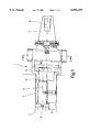
FIG. 1 shows a basic side view of a facing head,
FIG. 2 shows a cross section through the facing head in FIG. 1, and
FIG. 3 schematically illustrates a brake in the facing head.
DETAILED DESCRIPTION OF THE INVENTION
FIG. 1 shows a facing head 1 which comprises a steep angle taper 3, which is capable of being introduced into a machine spindle, not illustrated, of a machine tool. It has a tool head 5 with a rotary slide 7, on which one or more cutter plates for machining a plane face can be mounted. The rotary slide is rotatable about an axis of rotation 9, which is arranged offset, upwardly here, relative to a center axis 11 of the facing head 1. The rotary slide 7 is rotatable by a drive shaft 13 which is connected fixedly for rotation at its left end 15 to the rotary slide. A centrifugal drive 19 engages in a suitable way on the right end 17 of the drive shaft and the drive 19 is integrated into the facing head 1. The head 1 and the drive 19 are detailed in FIG. 2.
FIG. 2 shows a longitudinal section perpendicular to the center axis 11 and through the facing head 1, showing the centrifugal drive 19 according to FIG. 1, as seen from the right.
The centrifugal drive 19 comprises at least two driving bodies 21 and 23 which are arranged preferably in a plane running perpendicularly to the center axis 11, that is, in the image plane of FIG. 2. They are accommodated in suitable respective recesses 25 and 27 in the base body 29 of the facing head 1. The outer contours of the driving bodies 21 and 23 are coordinated with the contours of the respective recesses 25 and 27, such that the driving bodies are mounted displaceably in the base body 29. The frictional forces between the driving bodies 21 and 23 and the base body 29 are selected so that, when the facing head 1 rotates, the driving bodies can be displaced outwardly, as indicated by double arrows 31 and 33, on account of the centrifugal forces which act radially outwardly from the center axis 11. The driving bodies 21 and 23 are preferably displaced radially, since that is when the lowest friction forces occur. However, under centrifugal force, it is also possible that the driving bodies are displaced at an angle to an imaginary perpendicular to the center axis 11, that is, not directly radially.
The driving bodies 21 and 23 are provided with a coupling device 35 which couples the movements of the two driving bodies 21 and 23 or synchronizes them such that they move in the same way but in the opposite directions with respect to the center axis 11 or with respect to a plane E coinciding with the center axis 11. The coupling device 35 ensures that the facing head 1 remains in the balanced state even when the driving bodies 21 and 23 are displaced.
The coupling device 35 has a first rack 37 coupled to the first driving body 21 and a second rack 39 coupled to the second driving body 23 in such a way that the racks move together with their respective driving bodies. When the driving bodies 21 and 23 are moved outwardly by centrifugal force, according to the double arrows 31 and 33, the first rack 37, together with the first driving body 21, and the second rack 39, together with the second driving body 23, are displaced outwardly here parallel to an imaginary perpendicular S which is perpendicular to the plane E or coinciding with an imaginary diameter line.
The racks 37 and 39 have teeth on their sides facing the center axis 11. For simplicity, the teeth 41, 43, etc. of the second rack 39 are illustrated, whereas those of the first rack 37 are merely indicated by two lines L1 and L2.
The teeth 41, 43, etc. mesh with a gear wheel 45 having a center axis and an axis of rotation which coincide with the center axis 11 and the wheel 45 is set in rotation during displacement of the racks 37 and 39 in such a way that, upon outward movement of the driving bodies 21 and 23 along the double arrows 31 and 33, clockwise rotation of the gear wheel 45 is induced. The gear wheel 45 couples the movements of the two driving bodies 21 and 23.
It is apparent that the driving bodies 21 and 23 and the associated racks 37 and 39 may also be arranged in mirror inverse relative to the perpendicular S, so that counterclockwise, rather than clockwise rotation of the gear wheel 45 takes place when the driving bodies are displaced outwardly.
The gear wheel 45 is coupled rotatively fixedly to the right end 17, illustrated in FIG. 1, of the drive shaft 13. Any desired intermediate elements, which transmit rotation of the gear wheel 45 to the drive shaft 13 and induce rotation of this drive shaft, may also be arranged here. It is particularly preferred to have direct coupling between the gear wheel 45 and the drive shaft 13, as it avoids an interposed gear assembly, giving the facing head 1 a particularly small and compact design. The movement of the driving bodies 21 and 23 drives the rotary slide 7 in dependence upon centrifugal force.
To achieve uniform rotation of the rotary slide 7 and, consequently, a uniform feed of the cutter plate, an oil brake shown in FIG. 3 is integrated into the facing head. The oil brake 70 is designed, for example, in such a way that a disk 72, into which a throttle 74 is integrated and which is mounted rotationally on the rotary slide 7, brakes the slide by conveying oil through the throttle to the right in FIG. 3. For the rapid return of the cutter plate, which is induced by spring force, the throttle includes a nonreturn valve, which allows the oil to flow back to the left, virtually without any throttling. The cutter plate is moved between two positions. During the movement from the first to the second position the workpiece is machined. That is why during this phase the cutting plate has to move slowly along the surface of the workpiece. The slow movement of the cutting plate is effected by the throttle device. During the reverse movement from the second position to the first position, the workpiece just having been machined is either removed and a new workpiece is delivered or the workpiece is carried into another spatial position so that another portion of it can be machined. This fast reverse movement is also effected by the throttle device. In FIG. 3, the centrifugal device is to the right and the rotary slide to the left of the brake 70.
The operation of the driving bodies 21 and 23 permits a plurality of driving bodies to be arranged along the center axis 11 which are introduced into the base body 29 of the facing head 1, if appropriate so as also to be offset at 90°. This embodiment reinforces the forces acting on the drive shaft 13.
The facing head 1 or the centrifugal drive 19 include a return device 47 which has at least one spring element 48. The spring element 48 here is a pneumatic compression spring which is supported, on the one hand, in the base body 29, on a suitable shoulder 49 serving as one abutment and, on the other hand, on a projection 51 provided on the second rack 39, which likewise serves as an other abutment.
The spring element 48 may have a highly compact design. It is accommodated in a recess 53 in the base body 29. It is clear that the return device 47 can be equipped with any desired type of spring element 48 acting as a compression spring.
Since the two driving bodies 21 and 23 are coupled to one another in a mechanically rigid manner via the coupling device 35, that is, via the racks 37 and 39 and via the gear wheel 45, a single spring element 48 is sufficient to produce a return device 47. Preferably, however, two spring elements 48 and 55 are arranged symmetrically to the perpendicular S, on the one hand, to increase the return forces and, on the other hand, to avoid imbalance of the facing head 1. The spring element 55 is indicated here merely in its region facing the shoulder 49'. It is otherwise identical to the spring element 48.
The spring element 48 exerts a force on the projection 51 in the direction of the double arrow 31, which is opposite the direction of displacement of the driving body 23. The direction of displacement is indicated by the double arrow 33 and is determined by centrifugal force.
The spring elements 48 and 55 of the return device 47 are designed such that displacement of the driving bodies 21 and 23 is determined only beyond a specific predetermined magnitude of the centrifugal force which acts in the direction of the double arrows 31 and 33. Until this limiting centrifugal force is exceeded, the gear wheel 45 is not moved by the racks 39 and 37. The rotary slide 7 therefore remains at rest. After the limiting rotational speed has been exceeded, the driving bodies 21 and 23 of the centrifugal drive 19 move outwardly, so that the gear wheel 45 and, consequently, the drive shaft 13 are moved via the racks 37 and 39. This rotates the rotary slide 7 and consequently displaces the cutter plate 8 coupled to the slide. That cutter plate consequently machines an annular region on a plane 8 face which is machined by means of the facing head 1.
If the centrifugal force falls below the predetermined value, the spring elements 48 and 55 can displace the driving bodies 21 and 23 in the direction of the center axis 11 or of the plane E, counter to the centrifugal force acting in the direction of the double arrows 31 and 33.
Return movement of the driving bodies 21 and 23 is induced by the spring elements 48 and 55 in the directions opposite to the double arrows 31, 33. Through the racks 37 and 39, this rotates the gear wheel 45 counterclockwise, so that the rotary slide 7 is also moved in the opposite direction via the drive shaft 13.
The facing head 1 has a very simple design. The design of the return device 47, or the spring element 48 or spring elements 48 and 55, causes radially outward movement of the driving bodies 21 and 23, and therefore causes rotation of the rotary slide 7, when a predeterminable rotation speed of the facing head i is exceeded. The limiting rotational speed of the facing head 1 is also determined by the weight or mass of the driving bodies 21 and 23. These may be comprised of metal, for example of the same material as the facing head 1, or else, preferably, of a so called heavy metal, for example sintered tungsten, having a density which is approximately twice as great as the density of the initial material of the facing head 1.
Through use of suitable gear wheels inside the facing head 1, a plurality of drive shafts and, consequently, a plurality of rotary slides can also be set in rotation by the driving bodies. The facing head 1 may be provided with more than a single rotary slide 7, as mentioned here in the description.
The facing head 1 has a very simple design so that conventional driving rods for rotating the rotary slide 7 may be dispensed with. The facing head 1 may therefore be used together with conventional machine spindles, without any adaptation, and may be readily employed in known CNC stations. The simple design of the facing head 1 gives it a relatively low space requirement, so that the facing head 1 can be highly compact. The coupling device 35 causes the tool to always be balanced, irrespective of the positions of the driving bodies 21 and 23. It is also possible, therefore, inter alia, to operate the facing head at very high rotational speeds, of up to 6000 revolutions per minute, and above. The simple design of the facing head 1 also requires very low maintenance.
Operation of the facing head is described. The facing head 1 is rotated when mounted on a spindle. Sufficient speed rotation of the facing head displaces the driving bodies 21 and 23 radially outward far enough under the centrifugal force and against the return spring 48, 55. When the driving bodies are displaced radially outward, they rotate the rotary slide 7 sufficiently so that the cutting plates 8 project out of the side of the facing head 1 and machine a surface (not shown). On the other hand, as the facing head rotation slows or stops, the driving bodies 21, 23 return inward, which rotates the rotary slide to a position so that the cutting plates no longer project outwardly enough to cut a surface. The purpose of the driving bodies is to reorient the rotary slide 7 and the cutting plates on the slide between a projecting cutting orientation and a non cutting orientation.
Although the present invention has been described in relation to a particular embodiment thereof, many other variations and modifications and other uses will become apparent to those skilled in the art. It is preferred, therefore, that the present invention be limited not by the specific disclosure herein, but only by the appended claims.

Claims (11)

What is claimed is:
1. A facing head comprising:
a housing having a center axis;
a rotary slide in the housing, the rotary slide having a rotation axis, the rotation axis being radially offset from the center axis of the housing;
at least one cutter plate mounted on the slide for rotation about the rotation axis;
a centrifugal drive in the facing head connected with the rotary slide for rotating the rotary slide about its axis of rotation between first and second positions, and the centrifugal drive being operable by rotation of the facing head;
the centrifugal drive including:
a base body;
at least two driving bodies mounted in the base body of the facing head and displaceable essentially perpendicular to the center axis of the facing head to rotate the rotary slide to the second position upon application of centrifugal force;
a return device for displacing the driving bodies radially inwardly to rotate the rotary slide to the first position when there is insufficient centrifugal force due to rotation of the facing head for displacing the driving bodies outwardly;
a coupling device connected between the return device and the driving bodies causing the driving bodies to displace in opposition to each other upon application of centrifugal force thereto and under the action of the return device and
a drive shaft in the housing extending along the rotation axis of the rotary slide and connected with the rotary slide for driving the rotary slide to rotate.
2. The facing head of claim 1, wherein the coupling device comprises:
a respective rack at each of the driving bodies and each rack is displaceable along with the respective driving body; and
a gear wheel on the rotary slide and connected with each of the racks for being rotated by the racks due to movement of the driving bodies.
3. The facing head of claim 2, wherein the return device comprises a compression spring for returning the driving bodies to move the slide to the first position.
4. The facing head of claim 3, wherein the compression spring extends parallel to the direction of movement of the respective driving body.
5. The facing head of claim 1, wherein the return device comprises a return spring for returning the driving bodies to move the slide to the first position.
6. The facing head of claim 5, wherein the return device comprises a respective spring element connected to each of the driving bodies for returning the driving bodies radially inwardly toward the center axis.
7. The facing head of claim 6, wherein the respective spring element for each driving body is comprised of a compression spring connected between the base body and the respective driving body.
8. The facing head of claim 7, wherein each compression spring extends parallel to the direction of movement of the respective driving body.
9. The facing head of claim 1, wherein the drive shaft is coupled to the centrifugal drive to be rotated thereby.
10. The facing head of claim 1, wherein the coupling device comprises:
a respective rack at each of the driving bodies and each rack is displaceable along with the respective driving body; and
a gear wheel on the rotary slide and connected with each of the racks for being rotated by the racks due to movement of the driving bodies; and
the drive shaft being coupled to the gear wheel.
11. The facing head of claim 1, further comprising a throttle device for influencing the movement induced by the centrifugal drive and for allowing a uniform braked rotational motion of the rotary slide in one direction to the second position and virtually non-braked return rotation of the rotary slide to the first position.
US09/241,974 1998-01-30 1999-02-01 Facing head with rotary slide Expired - Fee Related US6050159A (en)

Applications Claiming Priority (2)

Application Number Priority Date Filing Date Title
DE19803613A DE19803613C2 (en) 1998-01-30 1998-01-30 Facing head
DE19803613 1998-01-30

Publications (1)

Publication Number Publication Date
US6050159A true US6050159A (en) 2000-04-18

Family

ID=7856144

Family Applications (1)

Application Number Title Priority Date Filing Date
US09/241,974 Expired - Fee Related US6050159A (en) 1998-01-30 1999-02-01 Facing head with rotary slide

Country Status (4)

Country Link
US (1) US6050159A (en)
EP (1) EP0933154A3 (en)
JP (1) JPH11277316A (en)
DE (1) DE19803613C2 (en)

Cited By (5)

* Cited by examiner, † Cited by third party
Publication number Priority date Publication date Assignee Title
US6487945B1 (en) * 1999-09-30 2002-12-03 Kummer Freres S.A. Tool head
US6655883B2 (en) 1999-10-27 2003-12-02 Wohlhaupter Gmbh Tool holder
US20070039440A1 (en) * 2005-08-22 2007-02-22 Climax Portable Machine Tools, Inc. Machine tool
US20120294685A1 (en) * 2011-05-17 2012-11-22 Andy Shozda Dual blade boring tool assembly
CN112024920A (en) * 2020-08-21 2020-12-04 浙江大学 Multi-machining-size boring cutter suitable for reconfigurable machine tool

Families Citing this family (2)

* Cited by examiner, † Cited by third party
Publication number Priority date Publication date Assignee Title
DE19960350A1 (en) * 1999-12-14 2001-06-21 Komet Stahlhalter Werkzeuge Tool drive for machine tools
CN107552837B (en) * 2017-10-24 2020-04-17 温州普睿达机械科技有限公司 Communication tower is built and is used tubular product drilling equipment

Citations (5)

* Cited by examiner, † Cited by third party
Publication number Priority date Publication date Assignee Title
US3289554A (en) * 1962-11-06 1966-12-06 Reynolds Metals Co Method and apparatus for rotating and/or axially advancing tubular stock or the like
GB2066128A (en) * 1979-12-29 1981-07-08 Komet Stahlhalter Werkzeug Compensating centrifugal forces in a rotary rotary tool head
DE4125106A1 (en) * 1991-07-30 1993-02-04 Wozar Tiberius Turning-tool arrangements with centrifugal adjusters - have built-in weights which adjust the tool relative to the rotational speed of the spindle
US5528830A (en) * 1994-02-18 1996-06-25 Hansen; Fredrick M. Rotary cutting tool for tubing, conduit and the like
US5759000A (en) * 1994-10-12 1998-06-02 Walter W. Wawrzyniak Generating head assembly with generating head and rotary power actuator

Patent Citations (5)

* Cited by examiner, † Cited by third party
Publication number Priority date Publication date Assignee Title
US3289554A (en) * 1962-11-06 1966-12-06 Reynolds Metals Co Method and apparatus for rotating and/or axially advancing tubular stock or the like
GB2066128A (en) * 1979-12-29 1981-07-08 Komet Stahlhalter Werkzeug Compensating centrifugal forces in a rotary rotary tool head
DE4125106A1 (en) * 1991-07-30 1993-02-04 Wozar Tiberius Turning-tool arrangements with centrifugal adjusters - have built-in weights which adjust the tool relative to the rotational speed of the spindle
US5528830A (en) * 1994-02-18 1996-06-25 Hansen; Fredrick M. Rotary cutting tool for tubing, conduit and the like
US5759000A (en) * 1994-10-12 1998-06-02 Walter W. Wawrzyniak Generating head assembly with generating head and rotary power actuator

Cited By (8)

* Cited by examiner, † Cited by third party
Publication number Priority date Publication date Assignee Title
US6487945B1 (en) * 1999-09-30 2002-12-03 Kummer Freres S.A. Tool head
US6655883B2 (en) 1999-10-27 2003-12-02 Wohlhaupter Gmbh Tool holder
US20070039440A1 (en) * 2005-08-22 2007-02-22 Climax Portable Machine Tools, Inc. Machine tool
US7793574B2 (en) * 2005-08-22 2010-09-14 Climax Portable Machine Tools Inc. Machine tool
US20120294685A1 (en) * 2011-05-17 2012-11-22 Andy Shozda Dual blade boring tool assembly
US8678721B2 (en) * 2011-05-17 2014-03-25 Barbara Shozda Dual blade boring tool assembly
CN112024920A (en) * 2020-08-21 2020-12-04 浙江大学 Multi-machining-size boring cutter suitable for reconfigurable machine tool
CN112024920B (en) * 2020-08-21 2021-09-24 浙江大学 Multi-machining-size boring cutter suitable for reconfigurable machine tool

Also Published As

Publication number Publication date
EP0933154A3 (en) 2001-09-19
JPH11277316A (en) 1999-10-12
DE19803613A1 (en) 1999-08-12
EP0933154A2 (en) 1999-08-04
DE19803613C2 (en) 2002-09-19

Similar Documents

Publication Publication Date Title
US5679066A (en) Eccentric disk grinder with a grinding disk brake
CN101862972B (en) Rotational resistance applying device in main shaft driving device for machine tool
US6050159A (en) Facing head with rotary slide
US4040315A (en) Machining cross-feed head counterweight system
US4689918A (en) Apparatus for manufacturing and working of gears
US5839860A (en) Intertially activated spotfacing and counterboring tool
EP0807489B1 (en) Device and method for indexing the phase of a crank pin
GB2073063A (en) Multi-position Tool Turret
CN102649247A (en) Processing apparatus with feeler roller
US5386743A (en) Turret indexing device
JP6514497B2 (en) Shaft coupling, damper device, impact torque reduction device and component fastening machine
US4532830A (en) Sawtooth grinding machine
JPS6232050B2 (en)
US4649671A (en) Method for the precision working of the flanks of gears with a gear-shaped tool coated with hard-material granules and a method for dressing such a tool
JPS5953140A (en) Drive for main spindle of turret type machine tool
JPS59156613A (en) Method and machine for manufacturing or machining gear
US5749273A (en) Method and apparatus for advancing a tool on a lathe
JPH03111103A (en) Spindle stock with hybrid bearing
NL8100690A (en) TOOL CHANGER.
JPS6036901B2 (en) Spindle indexing and rotation drive device
US2340735A (en) Tool feeding mechanism
US2294014A (en) Gear cutting machine
JPH0446687B2 (en)
US5101700A (en) Rotatable tool head
US2316106A (en) Driving means for the slides of machine tools

Legal Events

Date Code Title Description
AS Assignment

Owner name: MAPAL FABRIK FUR PRAZISIONSWERKZEUGE, GERMANY

Free format text: ASSIGNMENT OF ASSIGNORS INTEREST;ASSIGNORS:KRESS, DIETER;BECK, HANS W.;JAGER, HERBERT;REEL/FRAME:009864/0226

Effective date: 19990128

FEPP Fee payment procedure

Free format text: PAYOR NUMBER ASSIGNED (ORIGINAL EVENT CODE: ASPN); ENTITY STATUS OF PATENT OWNER: LARGE ENTITY

FPAY Fee payment

Year of fee payment: 4

REMI Maintenance fee reminder mailed
FPAY Fee payment

Year of fee payment: 8

FEPP Fee payment procedure

Free format text: PAYOR NUMBER ASSIGNED (ORIGINAL EVENT CODE: ASPN); ENTITY STATUS OF PATENT OWNER: LARGE ENTITY

Free format text: PAYER NUMBER DE-ASSIGNED (ORIGINAL EVENT CODE: RMPN); ENTITY STATUS OF PATENT OWNER: LARGE ENTITY

REMI Maintenance fee reminder mailed
LAPS Lapse for failure to pay maintenance fees
STCH Information on status: patent discontinuation

Free format text: PATENT EXPIRED DUE TO NONPAYMENT OF MAINTENANCE FEES UNDER 37 CFR 1.362

FP Lapsed due to failure to pay maintenance fee

Effective date: 20120418