US6032566A - Lever operated punch with strengthened flap and punch head adjustment arrangement - Google Patents
Lever operated punch with strengthened flap and punch head adjustment arrangement Download PDFInfo
- Publication number
- US6032566A US6032566A US09/122,184 US12218498A US6032566A US 6032566 A US6032566 A US 6032566A US 12218498 A US12218498 A US 12218498A US 6032566 A US6032566 A US 6032566A
- Authority
- US
- United States
- Prior art keywords
- base
- slipper
- punch
- opening
- heads
- Prior art date
- Legal status (The legal status is an assumption and is not a legal conclusion. Google has not performed a legal analysis and makes no representation as to the accuracy of the status listed.)
- Expired - Lifetime
Links
- 238000005728 strengthening Methods 0.000 abstract 1
- 239000002184 metal Substances 0.000 description 2
Images


Classifications
-
- B—PERFORMING OPERATIONS; TRANSPORTING
- B26—HAND CUTTING TOOLS; CUTTING; SEVERING
- B26F—PERFORATING; PUNCHING; CUTTING-OUT; STAMPING-OUT; SEVERING BY MEANS OTHER THAN CUTTING
- B26F1/00—Perforating; Punching; Cutting-out; Stamping-out; Apparatus therefor
- B26F1/32—Hand-held perforating or punching apparatus, e.g. awls
- B26F1/36—Punching or perforating pliers
-
- B—PERFORMING OPERATIONS; TRANSPORTING
- B26—HAND CUTTING TOOLS; CUTTING; SEVERING
- B26F—PERFORATING; PUNCHING; CUTTING-OUT; STAMPING-OUT; SEVERING BY MEANS OTHER THAN CUTTING
- B26F1/00—Perforating; Punching; Cutting-out; Stamping-out; Apparatus therefor
- B26F1/02—Perforating by punching, e.g. with relatively-reciprocating punch and bed
-
- Y—GENERAL TAGGING OF NEW TECHNOLOGICAL DEVELOPMENTS; GENERAL TAGGING OF CROSS-SECTIONAL TECHNOLOGIES SPANNING OVER SEVERAL SECTIONS OF THE IPC; TECHNICAL SUBJECTS COVERED BY FORMER USPC CROSS-REFERENCE ART COLLECTIONS [XRACs] AND DIGESTS
- Y10—TECHNICAL SUBJECTS COVERED BY FORMER USPC
- Y10T—TECHNICAL SUBJECTS COVERED BY FORMER US CLASSIFICATION
- Y10T83/00—Cutting
- Y10T83/222—With receptacle or support for cut product
-
- Y—GENERAL TAGGING OF NEW TECHNOLOGICAL DEVELOPMENTS; GENERAL TAGGING OF CROSS-SECTIONAL TECHNOLOGIES SPANNING OVER SEVERAL SECTIONS OF THE IPC; TECHNICAL SUBJECTS COVERED BY FORMER USPC CROSS-REFERENCE ART COLLECTIONS [XRACs] AND DIGESTS
- Y10—TECHNICAL SUBJECTS COVERED BY FORMER USPC
- Y10T—TECHNICAL SUBJECTS COVERED BY FORMER US CLASSIFICATION
- Y10T83/00—Cutting
- Y10T83/869—Means to drive or to guide tool
- Y10T83/8821—With simple rectilinear reciprocating motion only
- Y10T83/8828—Plural tools with same drive means
-
- Y—GENERAL TAGGING OF NEW TECHNOLOGICAL DEVELOPMENTS; GENERAL TAGGING OF CROSS-SECTIONAL TECHNOLOGIES SPANNING OVER SEVERAL SECTIONS OF THE IPC; TECHNICAL SUBJECTS COVERED BY FORMER USPC CROSS-REFERENCE ART COLLECTIONS [XRACs] AND DIGESTS
- Y10—TECHNICAL SUBJECTS COVERED BY FORMER USPC
- Y10T—TECHNICAL SUBJECTS COVERED BY FORMER US CLASSIFICATION
- Y10T83/00—Cutting
- Y10T83/869—Means to drive or to guide tool
- Y10T83/8821—With simple rectilinear reciprocating motion only
- Y10T83/8841—Tool driver movable relative to tool support
- Y10T83/885—Fixed axis lever
- Y10T83/8851—Adjustable mechanical advantage
Definitions
- the present invention is a slippered adjustable hand-operated punch with adjustment accomplished from the bottom of the punch without slipper removal.
- the flap handle is configured for added strength.
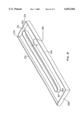
- FIG. 1 is a perspective view of the punch of the present invention having a handle and a lever;
- FIG. 2 is a sectional view taken along line 2--2 of FIG. 1 showing the flap handle's reverse curl;
- FIG. 3 is a perspective view of the punch with lever removed
- FIG. 4 is a sectional view along line 4--4 of FIG. 3;
- FIG. 5 is a bottom perspective view of the punch with slipper removed
- FIG. 6 is a partial perspective bottom view of the punch with the slipper installed
- FIG. 7 is a top perspective view of the base with the slipper extended for emptying
- FIG. 8 is a top perspective view of the slipper
- FIG. 9 is a plan view of the flap handle.
- FIG. 10 is an elevational view of the handle viewed from the reverse curl edge.
- punch 10 includes base 11, end uprights 12a, 12b, handle 14 including upper planar surface 13, handle depressions 13a, 13b, 13c mounted for pivoting around pivot pins 16a, 16b on end uprights 12a, 12b.
- Lever 17 is pivotally mounted on brackets 18a, 18b.
- punch assembly heads 21a, 21b, 21c and slipper 23 mounted on base rails 11a, 11b.
- Punch assembly heads 21a-c include punch pins P and curled projections 34a-c which reside in groove 40 to prevent turning of punch assembly heads 21a-c as they are translated (see also FIG. 7).
- handle 14 is formed of a sheet metal and comprises remote flange portion 14a substantially perpendicular to upper planar surface 13, (remote from pivot pins 16a, 16b); remote planar portion 14b, handle depression 13a, near planar portion 14c; near flange portion 14d perpendicular to upper planar surface 13 and reverse curl portion 15.
- Reverse curl portion 15 functions to stiffen and otherwise strengthen handle 14 and includes arc portion 15a and upright lip portion 15b.
- the sheet metal of handle 14 has thickness T.
- Table 1 below outlines ranges of handle 14 portions in relationship to thickness T.
- punch assembly heads 21a, 21b and 21c are adjustable using retaining screws 26a, 26b and 26c which travel in adjustment slots 27, 28 (FIG. 5) while the curled projections 34a-c travel in the longitudinal groove 40.
- Groove 40 is a longitudinal area below upper frame surface 11u and above a lower frame surface 11l. Curled projections 34a-c extend beyond and below upper frame surface 11u which permits the curled projections 34a-c to move back and forth in groove 40 during adjustment of the punch assembly heads and while preventing rotation of the heads 21a-c during their loosening. If a punch assembly head 21a-c attempts to rotate, its curled projection 34a-c will engage frame edge lie to prevent such rotation.
- Curled projections 34a-c may be of other shapes but a curved curled shape is preferred.
- the retaining screws 26a-c are threadedly engaged in threaded housing openings 31a, 31b and 31c (FIG. 4).
- Punch pin P is shown in FIG. 4.
- Base bottom 11c is shown in FIG. 5.
- Slipper 23 has a center opening 29 to permit access to the retaining screws 26a-c without removing the slipper 23.
- FIG. 7 shows the slipper 23 slid open for emptying and further shows the base rail 11a, 11b, end uprights 12a, 12b, slots 27, 28, retaining screws 26a-c, and groove 40.
- the slipper's center opening 29 is bounded by cowling 36 having ends 29a, 29b which cowling 36 has a height 36h sufficient to nearly abut the base bottom 11c to prevent paper punch outs or chips from escaping and exiting through center opening 29. Also shown are slipper flanges 23a, 23b and slipper slotted end 23c, and slipper closed end 23d. Slots 37a, 37b permit the slipper 23 to be slid open without removal from the base rails 11a, 11b. When slipper 23 is slid open, end 29a of the cowling 36 engages retaining screw 26c to limit its travel.
- Center opening 29 is longer than the distance (D) between outside retaining screws 26a and 26c to permit sliding of the slipper 23 relative to the base 11.
- the length of the opening 29 is less than the overall length of the slipper 23 so that paper punch outs which are all deposited on one side of cowling 36 can migrate past ends 29a, 29b to the other side as punch 10 is handled and manipulated.
- the reverse curl portion 15 of handle 14 has a length B which is less than the overall length A of handle 14.
- length B is at least 60% of length A.
Landscapes
- Life Sciences & Earth Sciences (AREA)
- Forests & Forestry (AREA)
- Engineering & Computer Science (AREA)
- Mechanical Engineering (AREA)
- Footwear And Its Accessory, Manufacturing Method And Apparatuses (AREA)
- Perforating, Stamping-Out Or Severing By Means Other Than Cutting (AREA)
- Press Drives And Press Lines (AREA)
- Holders For Apparel And Elements Relating To Apparel (AREA)
Abstract
Description
              TABLE 1
______________________________________
Portion(s)        Dimension
                           Range
______________________________________
1.     Near flange portion
                      a        6T-8T
2.     Curl portion width
                       b                     2.5T-4T
3.     Curl portion depth
                       c                     2.5T-4T
4.     Near flange portion
                      d                     9T-11T
       plus depth of curl
       portion
______________________________________
Claims (5)
Priority Applications (1)
| Application Number | Priority Date | Filing Date | Title |
|---|---|---|---|
| US09/122,184 US6032566A (en) | 1995-08-17 | 1998-07-24 | Lever operated punch with strengthened flap and punch head adjustment arrangement |
Applications Claiming Priority (3)
| Application Number | Priority Date | Filing Date | Title |
|---|---|---|---|
| US08/516,022 US5787783A (en) | 1995-08-17 | 1995-08-17 | Lever operated punch with strengthened flap and punch head adjustment arrangement |
| US08/697,934 US5797308A (en) | 1995-08-17 | 1996-09-03 | Hole punch having a slidable slipper and adjustable punches |
| US09/122,184 US6032566A (en) | 1995-08-17 | 1998-07-24 | Lever operated punch with strengthened flap and punch head adjustment arrangement |
Related Parent Applications (1)
| Application Number | Title | Priority Date | Filing Date |
|---|---|---|---|
| US08/697,934 Continuation US5797308A (en) | 1995-08-17 | 1996-09-03 | Hole punch having a slidable slipper and adjustable punches |
Publications (1)
| Publication Number | Publication Date |
|---|---|
| US6032566A true US6032566A (en) | 2000-03-07 |
Family
ID=24053789
Family Applications (4)
| Application Number | Title | Priority Date | Filing Date |
|---|---|---|---|
| US08/516,022 Expired - Lifetime US5787783A (en) | 1995-08-17 | 1995-08-17 | Lever operated punch with strengthened flap and punch head adjustment arrangement |
| US08/697,934 Expired - Lifetime US5797308A (en) | 1995-08-17 | 1996-09-03 | Hole punch having a slidable slipper and adjustable punches |
| US08/802,611 Expired - Lifetime US5829334A (en) | 1995-08-17 | 1997-02-19 | Lever operated punch with punch head adjustment arrangement |
| US09/122,184 Expired - Lifetime US6032566A (en) | 1995-08-17 | 1998-07-24 | Lever operated punch with strengthened flap and punch head adjustment arrangement |
Family Applications Before (3)
| Application Number | Title | Priority Date | Filing Date |
|---|---|---|---|
| US08/516,022 Expired - Lifetime US5787783A (en) | 1995-08-17 | 1995-08-17 | Lever operated punch with strengthened flap and punch head adjustment arrangement |
| US08/697,934 Expired - Lifetime US5797308A (en) | 1995-08-17 | 1996-09-03 | Hole punch having a slidable slipper and adjustable punches |
| US08/802,611 Expired - Lifetime US5829334A (en) | 1995-08-17 | 1997-02-19 | Lever operated punch with punch head adjustment arrangement |
Country Status (5)
| Country | Link |
|---|---|
| US (4) | US5787783A (en) |
| CN (3) | CN1262404C (en) |
| CA (1) | CA2202865C (en) |
| MX (1) | MX9702793A (en) |
| WO (1) | WO1997006934A1 (en) |
Cited By (23)
| Publication number | Priority date | Publication date | Assignee | Title |
|---|---|---|---|---|
| US6644161B2 (en) * | 2001-11-09 | 2003-11-11 | Gino Lu | Paper punch with multiple punch heads |
| US20040164138A1 (en) * | 2003-02-24 | 2004-08-26 | Chien-Fu Lin | Punch with punch elements in adjustable positions |
| US20050028659A1 (en) * | 2003-08-04 | 2005-02-10 | Chien-Fu Lin | Card corner cutter |
| US20050145085A1 (en) * | 2004-01-06 | 2005-07-07 | Ying-Chou Lee | Punch structure |
| US20060144206A1 (en) * | 2004-01-06 | 2006-07-06 | Ying-Chou Lee | Punch structure |
| US20070151435A1 (en) * | 2005-12-29 | 2007-07-05 | Acco Brands Usa Llc | Punch head housing |
| US20070199424A1 (en) * | 2006-01-23 | 2007-08-30 | Marks Joel S | Compact heavy duty hole punch |
| USD564594S1 (en) | 2007-03-30 | 2008-03-18 | Staples The Office Superstore, Llc | Hole punch |
| USD564593S1 (en) | 2007-03-30 | 2008-03-18 | Staples The Office Superstore, Llc | Hole punch |
| US20080092711A1 (en) * | 2006-10-19 | 2008-04-24 | Mate Precision Tooling, Inc. | Multiple punch and die assembly providing hand disassembly, punch length adjustment and replacement |
| US20080168874A1 (en) * | 2007-01-16 | 2008-07-17 | Officemate International Corporation | Lever handled paper punch |
| US20080236353A1 (en) * | 2007-03-30 | 2008-10-02 | Staples Brands Group | Hole punch |
| EP2014428A1 (en) * | 2007-07-07 | 2009-01-14 | Sdi Corporation | Hole puncher |
| US20090049967A1 (en) * | 2007-08-22 | 2009-02-26 | Chun-Yuan Chang | Hole punch structure |
| USD588647S1 (en) * | 2008-02-08 | 2009-03-17 | Officemate International Corporation | Hole punch |
| USD592250S1 (en) | 2007-12-19 | 2009-05-12 | Acco Brands Usa Llc | Sheet punch |
| US20090158908A1 (en) * | 2007-12-21 | 2009-06-25 | Acco Brands Usa Llc | Chip cartridge for sheet punch |
| US20100107847A1 (en) * | 2008-11-04 | 2010-05-06 | Staples The Office Superstore, Llc | Hole punch |
| US20100126325A1 (en) * | 2008-11-26 | 2010-05-27 | Eric Tsai | Effort-Saving Hand Operated Punching Device |
| US7954404B2 (en) | 2008-04-29 | 2011-06-07 | Mate Precision Tooling, Inc. | Punch device with adjustment subassembly as retrofit insert or as original equipment |
| USD658716S1 (en) | 2011-05-25 | 2012-05-01 | Staples The Office Superstore, Llc | Hole punch |
| USD717868S1 (en) * | 2014-01-02 | 2014-11-18 | Officemate International Corporation | Hole punch |
| US8936189B2 (en) | 2012-07-20 | 2015-01-20 | Officemate International Corporation | Switchable hole punch apparatus |
Families Citing this family (27)
| Publication number | Priority date | Publication date | Assignee | Title |
|---|---|---|---|---|
| US5787783A (en) * | 1995-08-17 | 1998-08-04 | Acco Brands, Inc. | Lever operated punch with strengthened flap and punch head adjustment arrangement |
| US6536321B2 (en) | 1996-03-05 | 2003-03-25 | Performance Design, Inc. | Hole punch quick-change die assembly with clamp system |
| US6363826B1 (en) | 1996-03-05 | 2002-04-02 | Performance Design, Inc. | Hole punch quick-change die assembly with pin strap and positioning system |
| DE19912042A1 (en) * | 1999-03-17 | 2000-09-21 | Esselte Leitz Gmbh & Co Kg | Waste tray for punchers |
| US6109155A (en) * | 1999-05-10 | 2000-08-29 | Huang; Bao-Ruh | Punch |
| USD445832S1 (en) | 2000-08-29 | 2001-07-31 | Tung Yung Stationery Manufactory Limited | Paper punch |
| US6962094B2 (en) | 2001-01-24 | 2005-11-08 | Orscheln Products Llc | Adjustable pedal assembly |
| US6769339B2 (en) | 2001-06-25 | 2004-08-03 | General Binding Corporation | Die set pin retainer |
| US6983877B2 (en) * | 2002-01-28 | 2006-01-10 | Ko Joseph Y | Automatic hole punch |
| USD468360S1 (en) | 2002-02-11 | 2003-01-07 | Peter Chen | Three hole punch with colored designer rubber insert and grip |
| US7111540B2 (en) * | 2003-06-03 | 2006-09-26 | Sop Services, Inc. | Dual purpose puncher |
| WO2007070842A2 (en) * | 2005-12-15 | 2007-06-21 | Josef Berger | System and methods for initiating, maintaining, and delivering personalized information by communication server |
| US20080022829A1 (en) * | 2006-07-31 | 2008-01-31 | Helix Usa | Edge punch |
| USD567861S1 (en) * | 2007-01-26 | 2008-04-29 | Officemate International Corp. | Paper punch |
| CN101234494A (en) * | 2007-02-02 | 2008-08-06 | 利高文具制造厂有限公司 | hole punch |
| CN101932412B (en) * | 2007-03-30 | 2012-12-05 | 斯特普尔斯办公用品超市有限公司 | Hole punch |
| US7721636B2 (en) * | 2007-06-19 | 2010-05-25 | Sdi Corporation | Hole puncher |
| US20100058912A1 (en) * | 2008-09-10 | 2010-03-11 | Chien-Chuan Huang | Paper punch with assistance arm |
| USD678946S1 (en) * | 2011-10-20 | 2013-03-26 | Fiskars Brands, Inc. | Material punch |
| USD685030S1 (en) * | 2012-01-06 | 2013-06-25 | Fiskars Brands, Inc. | Material punch |
| US9227314B2 (en) | 2012-05-07 | 2016-01-05 | David J. Crorey | Device and kit for making images for jewelry and accessories |
| USD685823S1 (en) | 2012-05-07 | 2013-07-09 | David J. Crorey | Bracelet maker |
| USD684608S1 (en) | 2012-11-20 | 2013-06-18 | David J. Crorey | Button maker |
| CN103568068A (en) * | 2013-11-06 | 2014-02-12 | 南通中尧机电制造有限公司 | Perforating machine |
| US20160346952A1 (en) * | 2015-05-29 | 2016-12-01 | Janyce Rossall | Combination three-hole punch and two-hole punch |
| TWI637831B (en) * | 2017-08-10 | 2018-10-11 | 順德工業股份有限公司 | Labor-saving punching machine |
| USD935522S1 (en) * | 2019-05-30 | 2021-11-09 | Zebra Technologies Corporation | Media processing device |
Citations (24)
| Publication number | Priority date | Publication date | Assignee | Title |
|---|---|---|---|---|
| US1655315A (en) * | 1927-06-24 | 1928-01-03 | Boorum & Pease Company | Punch |
| US1728475A (en) * | 1928-09-13 | 1929-09-17 | Claude H Cavill | Punching machine |
| US1870055A (en) * | 1931-03-06 | 1932-08-02 | Fred J Kline | Paper perforating device |
| US2001161A (en) * | 1934-01-29 | 1935-05-14 | Harry D Snyder | Perforating device |
| US2137716A (en) * | 1937-04-28 | 1938-11-22 | Bates Mfg Co | Perforator |
| US2244320A (en) * | 1939-11-18 | 1941-06-03 | Wilson Jones Co | Punch |
| US2244660A (en) * | 1939-05-18 | 1941-06-10 | New England Paper Punch Compan | Punch |
| US2368790A (en) * | 1943-12-23 | 1945-02-06 | Wilson Jones Co | Punch |
| US2389105A (en) * | 1944-05-12 | 1945-11-13 | Acco Products Inc | Multiple perforator |
| US2474344A (en) * | 1946-01-16 | 1949-06-28 | Carpenter John Allan | Multihole punch |
| US2481883A (en) * | 1947-09-24 | 1949-09-13 | Metal Specialties Mfg Co | Punch apparatus |
| US2494836A (en) * | 1945-07-13 | 1950-01-17 | Wilson Jones Co | Perforating device |
| US2534094A (en) * | 1946-03-09 | 1950-12-12 | John A Yerkes | Paper punch |
| US3073199A (en) * | 1962-04-16 | 1963-01-15 | John A Yerkes | Variable hole pattern hand punch |
| US3176570A (en) * | 1963-03-07 | 1965-04-06 | Bates Mfg Co | Multiple punch |
| US3392913A (en) * | 1966-07-28 | 1968-07-16 | Hildaur L. Neilsen | Paper punch with slidable punch actuating plate |
| US3714857A (en) * | 1970-09-09 | 1973-02-06 | Swingline Inc | Punch |
| US4036088A (en) * | 1976-08-30 | 1977-07-19 | Rolodex Corporation | Paper punch with variable spacing |
| US4656907A (en) * | 1985-08-30 | 1987-04-14 | Velobind, Inc. | Paper punch |
| US4688457A (en) * | 1983-01-10 | 1987-08-25 | Rolodex Corporation | Heavy duty paper punch |
| US4700601A (en) * | 1986-04-28 | 1987-10-20 | Velo Bind Inc. | Punch pin head structure |
| US4713995A (en) * | 1985-10-03 | 1987-12-22 | Rolodex Corp. | Hole punch assembly |
| US4898055A (en) * | 1988-12-15 | 1990-02-06 | Neilsen Hildaur L | Adjustable multiple paper punch |
| US5787783A (en) * | 1995-08-17 | 1998-08-04 | Acco Brands, Inc. | Lever operated punch with strengthened flap and punch head adjustment arrangement |
Family Cites Families (2)
| Publication number | Priority date | Publication date | Assignee | Title |
|---|---|---|---|---|
| US2482218A (en) * | 1945-02-26 | 1949-09-20 | Wilson Jones Co | Paper perforating device |
| US4829867A (en) * | 1987-03-05 | 1989-05-16 | Neilsen Hildaur L | Paper punch apparatus with improved punch element |
-
1995
- 1995-08-17 US US08/516,022 patent/US5787783A/en not_active Expired - Lifetime
-
1996
- 1996-08-14 WO PCT/US1996/013109 patent/WO1997006934A1/en not_active Ceased
- 1996-08-14 CN CNB031077609A patent/CN1262404C/en not_active Expired - Lifetime
- 1996-08-14 CA CA002202865A patent/CA2202865C/en not_active Expired - Fee Related
- 1996-08-14 CN CNA031077587A patent/CN1506200A/en active Pending
- 1996-08-14 CN CNB961911964A patent/CN1160176C/en not_active Expired - Lifetime
- 1996-08-14 MX MX9702793A patent/MX9702793A/en not_active IP Right Cessation
- 1996-09-03 US US08/697,934 patent/US5797308A/en not_active Expired - Lifetime
-
1997
- 1997-02-19 US US08/802,611 patent/US5829334A/en not_active Expired - Lifetime
-
1998
- 1998-07-24 US US09/122,184 patent/US6032566A/en not_active Expired - Lifetime
Patent Citations (25)
| Publication number | Priority date | Publication date | Assignee | Title |
|---|---|---|---|---|
| US1655315A (en) * | 1927-06-24 | 1928-01-03 | Boorum & Pease Company | Punch |
| US1728475A (en) * | 1928-09-13 | 1929-09-17 | Claude H Cavill | Punching machine |
| US1870055A (en) * | 1931-03-06 | 1932-08-02 | Fred J Kline | Paper perforating device |
| US2001161A (en) * | 1934-01-29 | 1935-05-14 | Harry D Snyder | Perforating device |
| US2137716A (en) * | 1937-04-28 | 1938-11-22 | Bates Mfg Co | Perforator |
| US2244660A (en) * | 1939-05-18 | 1941-06-10 | New England Paper Punch Compan | Punch |
| US2244320A (en) * | 1939-11-18 | 1941-06-03 | Wilson Jones Co | Punch |
| US2368790A (en) * | 1943-12-23 | 1945-02-06 | Wilson Jones Co | Punch |
| US2389105A (en) * | 1944-05-12 | 1945-11-13 | Acco Products Inc | Multiple perforator |
| US2494836A (en) * | 1945-07-13 | 1950-01-17 | Wilson Jones Co | Perforating device |
| US2474344A (en) * | 1946-01-16 | 1949-06-28 | Carpenter John Allan | Multihole punch |
| US2534094A (en) * | 1946-03-09 | 1950-12-12 | John A Yerkes | Paper punch |
| US2481883A (en) * | 1947-09-24 | 1949-09-13 | Metal Specialties Mfg Co | Punch apparatus |
| US3073199A (en) * | 1962-04-16 | 1963-01-15 | John A Yerkes | Variable hole pattern hand punch |
| US3176570A (en) * | 1963-03-07 | 1965-04-06 | Bates Mfg Co | Multiple punch |
| US3392913A (en) * | 1966-07-28 | 1968-07-16 | Hildaur L. Neilsen | Paper punch with slidable punch actuating plate |
| US3714857A (en) * | 1970-09-09 | 1973-02-06 | Swingline Inc | Punch |
| US4036088A (en) * | 1976-08-30 | 1977-07-19 | Rolodex Corporation | Paper punch with variable spacing |
| US4688457A (en) * | 1983-01-10 | 1987-08-25 | Rolodex Corporation | Heavy duty paper punch |
| US4656907A (en) * | 1985-08-30 | 1987-04-14 | Velobind, Inc. | Paper punch |
| US4713995A (en) * | 1985-10-03 | 1987-12-22 | Rolodex Corp. | Hole punch assembly |
| US4700601A (en) * | 1986-04-28 | 1987-10-20 | Velo Bind Inc. | Punch pin head structure |
| US4898055A (en) * | 1988-12-15 | 1990-02-06 | Neilsen Hildaur L | Adjustable multiple paper punch |
| US5787783A (en) * | 1995-08-17 | 1998-08-04 | Acco Brands, Inc. | Lever operated punch with strengthened flap and punch head adjustment arrangement |
| US5797308A (en) * | 1995-08-17 | 1998-08-25 | Acco Brands, Inc. | Hole punch having a slidable slipper and adjustable punches |
Non-Patent Citations (4)
| Title |
|---|
| Office Depot Catalog 27, Fall, 1995, "ACCO Lever Paper Punch", includes picture and description of adjustable 3-hole paper punch, Part # 996-926. |
| Office Depot Catalog 27, Fall, 1995, ACCO Lever Paper Punch , includes picture and description of adjustable 3 hole paper punch, Part 996 926. * |
| Office Depot Catalog 33, Fall 1997, "ACCO Model 20L Lever Adjustable Punch", includes picture and description of adjustable 3-hole paper punch, Part # 996-926. |
| Office Depot Catalog 33, Fall 1997, ACCO Model 20L Lever Adjustable Punch , includes picture and description of adjustable 3 hole paper punch, Part 996 926. * |
Cited By (41)
| Publication number | Priority date | Publication date | Assignee | Title |
|---|---|---|---|---|
| US6644161B2 (en) * | 2001-11-09 | 2003-11-11 | Gino Lu | Paper punch with multiple punch heads |
| US20040164138A1 (en) * | 2003-02-24 | 2004-08-26 | Chien-Fu Lin | Punch with punch elements in adjustable positions |
| US6786395B1 (en) * | 2003-02-24 | 2004-09-07 | Chau Lih Rong Enterprise Co., Ltd. | Punch with punch elements in adjustable positions |
| US20050028659A1 (en) * | 2003-08-04 | 2005-02-10 | Chien-Fu Lin | Card corner cutter |
| US20050145085A1 (en) * | 2004-01-06 | 2005-07-07 | Ying-Chou Lee | Punch structure |
| US6925921B2 (en) * | 2004-01-06 | 2005-08-09 | Ying-Chou Lee | Punch structure |
| US20060144206A1 (en) * | 2004-01-06 | 2006-07-06 | Ying-Chou Lee | Punch structure |
| US7194942B2 (en) * | 2004-01-06 | 2007-03-27 | Ying Chou Lee | Punch structure |
| US20070151435A1 (en) * | 2005-12-29 | 2007-07-05 | Acco Brands Usa Llc | Punch head housing |
| US20070199424A1 (en) * | 2006-01-23 | 2007-08-30 | Marks Joel S | Compact heavy duty hole punch |
| US20070266836A1 (en) * | 2006-01-23 | 2007-11-22 | Worktools, Inc. | Compact heavy duty hole punch |
| US7654183B2 (en) | 2006-01-23 | 2010-02-02 | Worktools, Inc. | Compact heavy duty hole punch |
| US20100229701A1 (en) * | 2006-10-19 | 2010-09-16 | Mate Precision Tooling, Inc. | Multiple Punch and Die Assembly Providing Hand Disassembly, Punch Length Adjustment and Replacement |
| US20100212469A1 (en) * | 2006-10-19 | 2010-08-26 | Mate Precision Tooling, Inc. | Multiple Punch and Die Assembly Providing Hand Disassembly, Punch Length Adjustment and Replacement |
| US20080092711A1 (en) * | 2006-10-19 | 2008-04-24 | Mate Precision Tooling, Inc. | Multiple punch and die assembly providing hand disassembly, punch length adjustment and replacement |
| US7726554B2 (en) | 2006-10-19 | 2010-06-01 | Mate Precision Tooling Inc. | Multiple punch and die assembly providing hand disassembly, punch length adjustment and replacement |
| US8152052B2 (en) | 2006-10-19 | 2012-04-10 | Mate Precision Tooling, Inc. | Multiple punch and die assembly providing hand disassembly, punch length adjustment and replacement |
| US8376215B2 (en) | 2006-10-19 | 2013-02-19 | Mate Precision Tooling, Inc. | Multiple punch and die assembly |
| US8464928B2 (en) | 2006-10-19 | 2013-06-18 | Mate Precision Tooling, Inc. | Multiple punch and die assembly providing hand disassembly, punch length adjustment and replacement |
| US20080168874A1 (en) * | 2007-01-16 | 2008-07-17 | Officemate International Corporation | Lever handled paper punch |
| US7721635B2 (en) * | 2007-01-16 | 2010-05-25 | Officemate International Corporation | Lever handled paper punch |
| US7610838B2 (en) | 2007-03-30 | 2009-11-03 | Staples The Office Superstore, Llc | Hole punch |
| US20080236353A1 (en) * | 2007-03-30 | 2008-10-02 | Staples Brands Group | Hole punch |
| USD564593S1 (en) | 2007-03-30 | 2008-03-18 | Staples The Office Superstore, Llc | Hole punch |
| USD564594S1 (en) | 2007-03-30 | 2008-03-18 | Staples The Office Superstore, Llc | Hole punch |
| EP2014428A1 (en) * | 2007-07-07 | 2009-01-14 | Sdi Corporation | Hole puncher |
| US20090049967A1 (en) * | 2007-08-22 | 2009-02-26 | Chun-Yuan Chang | Hole punch structure |
| US7819045B2 (en) * | 2007-08-22 | 2010-10-26 | Chun-Yuan Chang | Hole punch structure |
| USD592250S1 (en) | 2007-12-19 | 2009-05-12 | Acco Brands Usa Llc | Sheet punch |
| US20090158908A1 (en) * | 2007-12-21 | 2009-06-25 | Acco Brands Usa Llc | Chip cartridge for sheet punch |
| US8651004B2 (en) | 2007-12-21 | 2014-02-18 | Acco Brands Usa Llc | Chip cartridge for sheet punch |
| USD588647S1 (en) * | 2008-02-08 | 2009-03-17 | Officemate International Corporation | Hole punch |
| US7954404B2 (en) | 2008-04-29 | 2011-06-07 | Mate Precision Tooling, Inc. | Punch device with adjustment subassembly as retrofit insert or as original equipment |
| US8347770B2 (en) | 2008-11-04 | 2013-01-08 | Staples The Office Superstore, Llc | Hole punch |
| US20100107847A1 (en) * | 2008-11-04 | 2010-05-06 | Staples The Office Superstore, Llc | Hole punch |
| US8109189B2 (en) | 2008-11-26 | 2012-02-07 | Apex Mfg. Co., Ltd. | Effort-saving hand operated punching device |
| US20100126325A1 (en) * | 2008-11-26 | 2010-05-27 | Eric Tsai | Effort-Saving Hand Operated Punching Device |
| USD658716S1 (en) | 2011-05-25 | 2012-05-01 | Staples The Office Superstore, Llc | Hole punch |
| USD669936S1 (en) | 2011-05-25 | 2012-10-30 | Staples The Office Superstore, Llc | Hole punch |
| US8936189B2 (en) | 2012-07-20 | 2015-01-20 | Officemate International Corporation | Switchable hole punch apparatus |
| USD717868S1 (en) * | 2014-01-02 | 2014-11-18 | Officemate International Corporation | Hole punch |
Also Published As
| Publication number | Publication date |
|---|---|
| CN1262404C (en) | 2006-07-05 |
| US5829334A (en) | 1998-11-03 |
| CN1507991A (en) | 2004-06-30 |
| US5787783A (en) | 1998-08-04 |
| CN1506200A (en) | 2004-06-23 |
| CN1173839A (en) | 1998-02-18 |
| MX9702793A (en) | 1997-06-28 |
| CA2202865C (en) | 2002-01-22 |
| CN1160176C (en) | 2004-08-04 |
| US5797308A (en) | 1998-08-25 |
| WO1997006934A1 (en) | 1997-02-27 |
| CA2202865A1 (en) | 1997-02-27 |
Similar Documents
| Publication | Publication Date | Title |
|---|---|---|
| US6032566A (en) | Lever operated punch with strengthened flap and punch head adjustment arrangement | |
| MXPA97002793A (en) | Punzon with sliding skate and punzones ajus | |
| US5524515A (en) | Support panel for a rotary paper cutter | |
| US5778750A (en) | Lever-operated push flap for manual punch | |
| US6460442B2 (en) | Rip fence with dual locking mechanism | |
| CA2029066C (en) | Improvements in roofing washer-dispensing machine | |
| US5954106A (en) | Work bench having an adjustable guide | |
| EP0226363B1 (en) | Punch | |
| US5730038A (en) | Configuration for paper punch pin | |
| CA2124141A1 (en) | Saw table with compound movement of saw | |
| DE3626168A1 (en) | TUNING DEVICE FOR STRING INSTRUMENTS | |
| GB2310400A (en) | Lockable ring binder with strengthened curved upper plate | |
| US4301744A (en) | Table slide device | |
| WO1997031345A1 (en) | Scales for retail outlets | |
| US5106222A (en) | Embossed cover for ring binder mechanism | |
| US5549433A (en) | Binding equipment | |
| US6698328B1 (en) | Mitre box | |
| US20240315490A1 (en) | Cutting board assembly with scrap mover | |
| US4173137A (en) | Bending fixture for offset plates | |
| US6972878B2 (en) | Scanner capable of adjusting the height of a paper cover | |
| US20020011140A1 (en) | Cutting die clamping mechanism | |
| US7093747B1 (en) | Mail box cover access and insert for masonry mail boxes | |
| DE9415661U1 (en) | Tool case | |
| USD356926S (en) | Plate | |
| USD385976S (en) | Flooring surface |
Legal Events
| Date | Code | Title | Description |
|---|---|---|---|
| STCF | Information on status: patent grant |
Free format text: PATENTED CASE |
|
| FEPP | Fee payment procedure |
Free format text: PAYOR NUMBER ASSIGNED (ORIGINAL EVENT CODE: ASPN); ENTITY STATUS OF PATENT OWNER: LARGE ENTITY |
|
| FPAY | Fee payment |
Year of fee payment: 4 |
|
| AS | Assignment |
Owner name: CITICORP NORTH AMERICA, AS ADMINISTRATIVE AGENT, I Free format text: PATENT SECURITY AGREEMENT;ASSIGNORS:ACCO BRANDS CORPORATION, A DELAWARE CORPORATION;ACCO BRANDS USA LLC, A DELAWARE LIMITED LIABILITY COMPANY BOONE INTERNATIONAL, INC., A CALIFORNIA CORPORATION GENERAL BINDING CORPORATION, A DELAWARE CORPORATION;BOONE INTERNATIONAL, INC., A CALIFORNIA CORPORATION;AND OTHERS;REEL/FRAME:016914/0813 Effective date: 20050817 |
|
| AS | Assignment |
Owner name: ACCO BRANDS USA LLC, ILLINOIS Free format text: CHANGE OF NAME;ASSIGNOR:ACCO BRANDS, INC.;REEL/FRAME:016674/0785 Effective date: 20050802 |
|
| FEPP | Fee payment procedure |
Free format text: PAYER NUMBER DE-ASSIGNED (ORIGINAL EVENT CODE: RMPN); ENTITY STATUS OF PATENT OWNER: LARGE ENTITY |
|
| FPAY | Fee payment |
Year of fee payment: 8 |
|
| REMI | Maintenance fee reminder mailed | ||
| AS | Assignment |
Owner name: ACCO BRANDS CORPORATION, ILLINOIS Free format text: RELEASE BY SECURED PARTY;ASSIGNOR:CITICORP NORTH AMERICA, INC.;REEL/FRAME:023312/0784 Effective date: 20090930 Owner name: ACCO BRANDS USA LLC, ILLINOIS Free format text: RELEASE BY SECURED PARTY;ASSIGNOR:CITICORP NORTH AMERICA, INC.;REEL/FRAME:023312/0784 Effective date: 20090930 Owner name: BOONE INTERNATIONAL, INC., ILLINOIS Free format text: RELEASE BY SECURED PARTY;ASSIGNOR:CITICORP NORTH AMERICA, INC.;REEL/FRAME:023312/0784 Effective date: 20090930 Owner name: GENERAL BINDING CORPORATION, ILLINOIS Free format text: RELEASE BY SECURED PARTY;ASSIGNOR:CITICORP NORTH AMERICA, INC.;REEL/FRAME:023312/0784 Effective date: 20090930 Owner name: U.S. BANK NATIONAL ASSOCIATION, ILLINOIS Free format text: SECURITY AGREEMENT;ASSIGNORS:ACCO BRANDS CORPORATION;ACCO BRANDS USA LLC;DAY-TIMERS INC.;AND OTHERS;REEL/FRAME:023312/0902 Effective date: 20090930 Owner name: ACCO BRANDS CORPORATION,ILLINOIS Free format text: RELEASE BY SECURED PARTY;ASSIGNOR:CITICORP NORTH AMERICA, INC.;REEL/FRAME:023312/0784 Effective date: 20090930 Owner name: ACCO BRANDS USA LLC,ILLINOIS Free format text: RELEASE BY SECURED PARTY;ASSIGNOR:CITICORP NORTH AMERICA, INC.;REEL/FRAME:023312/0784 Effective date: 20090930 Owner name: BOONE INTERNATIONAL, INC.,ILLINOIS Free format text: RELEASE BY SECURED PARTY;ASSIGNOR:CITICORP NORTH AMERICA, INC.;REEL/FRAME:023312/0784 Effective date: 20090930 Owner name: GENERAL BINDING CORPORATION,ILLINOIS Free format text: RELEASE BY SECURED PARTY;ASSIGNOR:CITICORP NORTH AMERICA, INC.;REEL/FRAME:023312/0784 Effective date: 20090930 Owner name: U.S. BANK NATIONAL ASSOCIATION,ILLINOIS Free format text: SECURITY AGREEMENT;ASSIGNORS:ACCO BRANDS CORPORATION;ACCO BRANDS USA LLC;DAY-TIMERS INC.;AND OTHERS;REEL/FRAME:023312/0902 Effective date: 20090930 |
|
| AS | Assignment |
Owner name: DEUTSCHE BANK AG NEW YORK BRANCH, NEW YORK Free format text: SECURITY AGREEMENT;ASSIGNORS:ACCO BRANDS CORPORATION;ACCO BRANDS USA LLC;DAY-TIMERS INC.;AND OTHERS;REEL/FRAME:023449/0180 Effective date: 20090930 Owner name: DEUTSCHE BANK AG NEW YORK BRANCH,NEW YORK Free format text: SECURITY AGREEMENT;ASSIGNORS:ACCO BRANDS CORPORATION;ACCO BRANDS USA LLC;DAY-TIMERS INC.;AND OTHERS;REEL/FRAME:023449/0180 Effective date: 20090930 |
|
| FPAY | Fee payment |
Year of fee payment: 12 |
|
| AS | Assignment |
Owner name: ACCO BRANDS CORPORATION, ILLINOIS Free format text: RELEASE BY SECURED PARTY;ASSIGNOR:DEUTSCHE BANK AG NEW YORK BRANCH, AS COLLATERAL AGENT;REEL/FRAME:028168/0738 Effective date: 20120430 Owner name: ACCO BRANDS CORPORATION, ILLINOIS Free format text: RELEASE BY SECURED PARTY;ASSIGNOR:U.S. BANK NATIONAL ASSOCIATION, AS COLLATERAL TRUSTEE;REEL/FRAME:028168/0713 Effective date: 20120430 |
|
| AS | Assignment |
Owner name: BARCLAYS BANK PLC, AS ADMINISTRATIVE AGENT, NEW YO Free format text: SECURITY AGREEMENT;ASSIGNOR:ACCO BRANDS USA LLC;REEL/FRAME:028217/0360 Effective date: 20120430 |
|
| AS | Assignment |
Owner name: GENERAL BINDING CORPORATION, ILLINOIS Free format text: CORRECTIVE ASSIGNMENT TO CORRECT THE MISSING ASSIGNEES ON THE RELEASE OF SECURITY INTEREST IN PATENTS PREVIOUSLY RECORDED ON REEL 028168 FRAME 0738. ASSIGNOR(S) HEREBY CONFIRMS THE ASSIGNEES ACCO BRANDS USA LLC, AND GENERAL BINDING CORPORATION ARE ADDITIONAL ASIGNEES;ASSIGNOR:DEUTSCHE BANK AG NEW YORK BRANK, AS COLLATERAL AGENT;REEL/FRAME:028488/0056 Effective date: 20120430 Owner name: ACCO BRANDS USA LLC, ILLINOIS Free format text: CORRECTIVE ASSIGNMENT TO CORRECT THE THE MISSING ASSIGNEES ON THE RELEASE OF SECURITY INTEREST IN PATENTS PREVIOUSLY RECORDED ON REEL 028168 FRAME 0713. ASSIGNOR(S) HEREBY CONFIRMS THE ASSIGNEES ACCO BRANDS USA LLC AND GENERAL BINDING CORPORATION ARE ADDITIONAL ASSIGNEES;ASSIGNOR:U.S. BANK NATIONAL ASSOCIATION, AS COLLATERAL TRUSTEE;REEL/FRAME:028487/0671 Effective date: 20120430 Owner name: ACCO BRANDS CORPORATION, ILLINOIS Free format text: CORRECTIVE ASSIGNMENT TO CORRECT THE MISSING ASSIGNEES ON THE RELEASE OF SECURITY INTEREST IN PATENTS PREVIOUSLY RECORDED ON REEL 028168 FRAME 0738. ASSIGNOR(S) HEREBY CONFIRMS THE ASSIGNEES ACCO BRANDS USA LLC, AND GENERAL BINDING CORPORATION ARE ADDITIONAL ASIGNEES;ASSIGNOR:DEUTSCHE BANK AG NEW YORK BRANK, AS COLLATERAL AGENT;REEL/FRAME:028488/0056 Effective date: 20120430 Owner name: ACCO BRANDS USA LLC, ILLINOIS Free format text: CORRECTIVE ASSIGNMENT TO CORRECT THE MISSING ASSIGNEES ON THE RELEASE OF SECURITY INTEREST IN PATENTS PREVIOUSLY RECORDED ON REEL 028168 FRAME 0738. ASSIGNOR(S) HEREBY CONFIRMS THE ASSIGNEES ACCO BRANDS USA LLC, AND GENERAL BINDING CORPORATION ARE ADDITIONAL ASIGNEES;ASSIGNOR:DEUTSCHE BANK AG NEW YORK BRANK, AS COLLATERAL AGENT;REEL/FRAME:028488/0056 Effective date: 20120430 Owner name: ACCO BRANDS CORPORATION, ILLINOIS Free format text: CORRECTIVE ASSIGNMENT TO CORRECT THE THE MISSING ASSIGNEES ON THE RELEASE OF SECURITY INTEREST IN PATENTS PREVIOUSLY RECORDED ON REEL 028168 FRAME 0713. ASSIGNOR(S) HEREBY CONFIRMS THE ASSIGNEES ACCO BRANDS USA LLC AND GENERAL BINDING CORPORATION ARE ADDITIONAL ASSIGNEES;ASSIGNOR:U.S. BANK NATIONAL ASSOCIATION, AS COLLATERAL TRUSTEE;REEL/FRAME:028487/0671 Effective date: 20120430 Owner name: GENERAL BINDING CORPORATION, ILLINOIS Free format text: CORRECTIVE ASSIGNMENT TO CORRECT THE THE MISSING ASSIGNEES ON THE RELEASE OF SECURITY INTEREST IN PATENTS PREVIOUSLY RECORDED ON REEL 028168 FRAME 0713. ASSIGNOR(S) HEREBY CONFIRMS THE ASSIGNEES ACCO BRANDS USA LLC AND GENERAL BINDING CORPORATION ARE ADDITIONAL ASSIGNEES;ASSIGNOR:U.S. BANK NATIONAL ASSOCIATION, AS COLLATERAL TRUSTEE;REEL/FRAME:028487/0671 Effective date: 20120430 |
|
| AS | Assignment |
Owner name: BANK OF AMERICA, N.A., AS NEW ADMINISTRATIVE AGENT Free format text: ASSIGNMENT AND ASSUMPTION OF INTELLECTUAL PROPERTY SECURITY AGREEMENT RECORDED AT R/F 028217/0360;ASSIGNOR:BARCLAYS BANK PLC, AS EXISTING ADMINISTRATIVE AGENT, EXISTING SWING LINE LENDER AND EXISTING L/C ISSUER;REEL/FRAME:030427/0574 Effective date: 20130513 |