US60272A - John e - Google Patents
John e Download PDFInfo
- Publication number
- US60272A US60272A US60272DA US60272A US 60272 A US60272 A US 60272A US 60272D A US60272D A US 60272DA US 60272 A US60272 A US 60272A
- Authority
- US
- United States
- Prior art keywords
- cutters
- knives
- ring
- plugs
- marked
- Prior art date
- Legal status (The legal status is an assumption and is not a legal conclusion. Google has not performed a legal analysis and makes no representation as to the accuracy of the status listed.)
- Expired - Lifetime
Links
- 239000000203 mixture Substances 0.000 description 6
- XEEYBQQBJWHFJM-UHFFFAOYSA-N iron Chemical compound [Fe] XEEYBQQBJWHFJM-UHFFFAOYSA-N 0.000 description 4
- 206010002368 Anger Diseases 0.000 description 2
- 229910001369 Brass Inorganic materials 0.000 description 2
- 229910001208 Crucible steel Inorganic materials 0.000 description 2
- 239000010951 brass Substances 0.000 description 2
- 229910052742 iron Inorganic materials 0.000 description 2
- 239000000463 material Substances 0.000 description 2
Images
Classifications
-
- B—PERFORMING OPERATIONS; TRANSPORTING
- B23—MACHINE TOOLS; METAL-WORKING NOT OTHERWISE PROVIDED FOR
- B23B—TURNING; BORING
- B23B51/00—Tools for drilling machines
- B23B51/04—Drills for trepanning
- B23B51/0473—Details about the connection between the driven shaft and the tubular cutting part; Arbors
-
- Y—GENERAL TAGGING OF NEW TECHNOLOGICAL DEVELOPMENTS; GENERAL TAGGING OF CROSS-SECTIONAL TECHNOLOGIES SPANNING OVER SEVERAL SECTIONS OF THE IPC; TECHNICAL SUBJECTS COVERED BY FORMER USPC CROSS-REFERENCE ART COLLECTIONS [XRACs] AND DIGESTS
- Y10—TECHNICAL SUBJECTS COVERED BY FORMER USPC
- Y10T—TECHNICAL SUBJECTS COVERED BY FORMER US CLASSIFICATION
- Y10T408/00—Cutting by use of rotating axially moving tool
- Y10T408/89—Tool or Tool with support
- Y10T408/895—Having axial, core-receiving central portion
Definitions
- Figure 2 a longitudinal section through one of the cutters, showing the manner in which the parts are held together.
- Figure 3 a plan view of the ring for holding the knives in place.
- Figure 4 is a similar view of a nut or ring for the same purpose.
- Figure 5 represents a plan of one of the cutters, showing the 4ends of the knives, and also the inside of the cutter.
- Figure 6 is a view of one of the knives for shaving off or tapering the-plugs or bungs.
- a and F represent the counter-shaft and driving pulleys
- B the frame ⁇ by which it is supported
- G is a belt running Afrom the pulley A to one of the pulleys marked G; there are as many of the'belts GJ as there are of the pulleys G to be driven; said pulleys are fastened to the spindles marked D, to which the' cutters C C C are fastened by set-screws, one of which isshown in fig. 1, and marked V.
- the spindles run in the boxes marked E, which are made in the usual way of iron, brass, or other suitable material; these boxes have grooves in the bottom which are made to fitupon the ways, X X, along which they can be movedy horizontally; they are fixed firmly in place by means of screws or the equivalent thereof, which work under the blocks marked H.
- the spindles and cutters are constructed of cast steel.
- the letters, I I represent a section of the knives, showing the way in which they are held in place.
- T- is a groove, of which there is one in each cutter; a front view is shownV in g.
- the bolt O in the meantime, is forced in against the spiral spring, B., as the plug is being cut, but springs out again when the pressure is taken oil', throwing the plug out with it.
- I represents the knife for shaving off and tapering the plug; it is fitted on to the tube, N, in the same manner as the rest of the knives, but the surface of said tube, and the projectiou or flange, L, is made to incline slightly inward toward the centre, as shown at W, in g.
- said knife may be adjusted to out any thickness of shaving desired, which is ,done by moving or sliding it around the said tube, N, either to or from the point shown at W, and then tightening .it with the nut, K, as before shown; it also allows the knife to be adjusted after it is worn'by grinding'onsharpening, A
Description
@eine gisten getwi- @Hita IMPROVEMENT .IN MACHINES EUR CUTTING BUNGS.
SPECIFICATION..
TO ALL WHOM IT MAY CONCERN: i
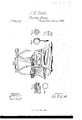
Bd it known that I, JOHN E. SMITH, of Buifalo, in the county of Erie, and State of New York, have invented certain new and useful Improvements in Machines for making Plugs and Bungs; and I do hereby declare that the following description thereof is sufficiently clear and exact to enable others skilled in the art to make and use the same, reference being had to the accompanying drawings, makinga part of this specification, in which-- Figure 1 is a perspective view. i
Figure 2, a longitudinal section through one of the cutters, showing the manner in which the parts are held together.
Figure 3, a plan view of the ring for holding the knives in place.
Figure 4 is a similar view of a nut or ring for the same purpose.
Figure 5 represents a plan of one of the cutters, showing the 4ends of the knives, and also the inside of the cutter.
Figure 6 is a view of one of the knives for shaving off or tapering the-plugs or bungs.
The nature of my invention consists inp 1. The manner of fastening the various parts of the cutter together, and in the employment of a bolt and spring to throw the plugs and bungs out when nished.
2. In the shape of the knife for tapering by means of which a sliding cut is given, thereby giving a smooth,
Aclean surface to the plugs, and a tapering or conical form; also, in the arrangement by which said knife is adjusted to cut any thickness of shaving desired. l
3. In the combination of two or more cutters when used in a machine for making plugs aud bungs, and in making said cutters, and the spindles to which they are attached, adjustable horizontally, for the purpose of placing them nearer together or farther apart, so that di`erent-sized cutters may be used.
The same letters in the several figures represent similar parts in each. l
In fig. 1, A and F represent the counter-shaft and driving pulleys, B the frame `by which it is supported; G is a belt running Afrom the pulley A to one of the pulleys marked G; there are as many of the'belts GJ as there are of the pulleys G to be driven; said pulleys are fastened to the spindles marked D, to which the' cutters C C C C are fastened by set-screws, one of which isshown in fig. 1, and marked V. The spindles run in the boxes marked E, which are made in the usual way of iron, brass, or other suitable material; these boxes have grooves in the bottom which are made to fitupon the ways, X X, along which they can be movedy horizontally; they are fixed firmly in place by means of screws or the equivalent thereof, which work under the blocks marked H. In using large or small cutters it is necessary to adjust the spindles, D, horizontally, near together or far apart, according to the size of the cutters. The spindles and cutters are constructed of cast steel. In fig. 2, the letters, I I, represent a section of the knives, showing the way in which they are held in place. T- is a groove, of which there is one in each cutter; a front view is shownV in g. 6. On the tube N, is a flange or ring projecting outward and surrounding it g'it is marked L. In putting the cutter together, the grooves,'T, in the knives are made to lit over the projection or ring L; the ring .I is then put on and slipped over the knives, which are made a little tapering where said ring fits over them, so that when the nut, K, is screwed up against it, the knives are held firmly in place. The nut K is moved by a wrench, as shown in fig. 4. The plugs are cut by pressing a board of the proper. thickness against the cutters, C, until they cut their way through it. The bolt O, in the meantime, is forced in against the spiral spring, B., as the plug is being cut, but springs out again when the pressure is taken oil', throwing the plug out with it. I represents the knife for shaving off and tapering the plug; it is fitted on to the tube, N, in the same manner as the rest of the knives, but the surface of said tube, and the projectiou or flange, L, is made to incline slightly inward toward the centre, as shown at W, in g. 5, so that said knife may be adjusted to out any thickness of shaving desired, which is ,done by moving or sliding it around the said tube, N, either to or from the point shown at W, and then tightening .it with the nut, K, as before shown; it also allows the knife to be adjusted after it is worn'by grinding'onsharpening, A
I not claim the combination of a number of cutting instruments for boring holesbas that has beeridone by a. number of angers or drills combined. I i i But what I do claim as my invention, and desire to secure by Letters Patent, is
The ring J, and nut K, in combination with the groove T, andthe llange or ring L, when constructed as and for the purposes described. i 4
JOI-IN E. SMITH.
Witnesses JAMES SANesrnn, F. CoLLIcoN.
Publications (1)
| Publication Number | Publication Date |
|---|---|
| US60272A true US60272A (en) | 1866-12-04 |
Family
ID=2129811
Family Applications (1)
| Application Number | Title | Priority Date | Filing Date |
|---|---|---|---|
| US60272D Expired - Lifetime US60272A (en) | John e |
Country Status (1)
| Country | Link |
|---|---|
| US (1) | US60272A (en) |
Cited By (1)
| Publication number | Priority date | Publication date | Assignee | Title |
|---|---|---|---|---|
| US20160153295A1 (en) * | 2013-10-31 | 2016-06-02 | Safran | Composite vane for a turbine engine |
-
0
- US US60272D patent/US60272A/en not_active Expired - Lifetime
Cited By (1)
| Publication number | Priority date | Publication date | Assignee | Title |
|---|---|---|---|---|
| US20160153295A1 (en) * | 2013-10-31 | 2016-06-02 | Safran | Composite vane for a turbine engine |
Similar Documents
| Publication | Publication Date | Title |
|---|---|---|
| US60272A (en) | John e | |
| US385201A (en) | Half to jean scherbel | |
| US1255760A (en) | Knife-sharpener. | |
| US743374A (en) | Cutter-head. | |
| US55661A (en) | Improvement in cutters for dovetailing-machines | |
| US417571A (en) | martianoni | |
| US52715A (en) | Improved tool for cutting gas-pipes | |
| US421962A (en) | Joseph o brien | |
| US215005A (en) | Improvement in tools for turning the ends of spools | |
| US58183A (en) | Daniel whitlook | |
| US219970A (en) | Improvement in turning implements for lathes | |
| US55833A (en) | Improvement in machines for planing moldings | |
| US202618A (en) | Improvement in hand-reamers | |
| US65303A (en) | Improvement in wood-splitting machines | |
| US54896A (en) | Improvement in machines for cutting corks | |
| US67654A (en) | John c | |
| US489876A (en) | Sole-trimming machine | |
| US1243909A (en) | Veneer-making machine for the manufacture of toothpicks. | |
| US313836A (en) | Ferrule seats on umbrella sticks | |
| US49981A (en) | Jeeemiah close | |
| US1016207A (en) | Tool. | |
| US54096A (en) | Improved screw-tap | |
| US822351A (en) | Rotary cutter. | |
| US96004A (en) | Improvement in straw-ctttters | |
| US54774A (en) | Improvement in mode of attach ing circular saws to their arbors |