US5995690A - Front light extraction film for light guiding systems and method of manufacture - Google Patents
Front light extraction film for light guiding systems and method of manufacture Download PDFInfo
- Publication number
- US5995690A US5995690A US08/755,767 US75576796A US5995690A US 5995690 A US5995690 A US 5995690A US 75576796 A US75576796 A US 75576796A US 5995690 A US5995690 A US 5995690A
- Authority
- US
- United States
- Prior art keywords
- light
- coupling element
- light coupling
- refractive index
- outer portion
- Prior art date
- Legal status (The legal status is an assumption and is not a legal conclusion. Google has not performed a legal analysis and makes no representation as to the accuracy of the status listed.)
- Expired - Lifetime
Links
Images


Classifications
-
- G—PHYSICS
- G02—OPTICS
- G02B—OPTICAL ELEMENTS, SYSTEMS OR APPARATUS
- G02B6/00—Light guides; Structural details of arrangements comprising light guides and other optical elements, e.g. couplings
- G02B6/0001—Light guides; Structural details of arrangements comprising light guides and other optical elements, e.g. couplings specially adapted for lighting devices or systems
- G02B6/0011—Light guides; Structural details of arrangements comprising light guides and other optical elements, e.g. couplings specially adapted for lighting devices or systems the light guides being planar or of plate-like form
- G02B6/0033—Means for improving the coupling-out of light from the light guide
- G02B6/005—Means for improving the coupling-out of light from the light guide provided by one optical element, or plurality thereof, placed on the light output side of the light guide
- G02B6/0053—Prismatic sheet or layer; Brightness enhancement element, sheet or layer
-
- G—PHYSICS
- G02—OPTICS
- G02B—OPTICAL ELEMENTS, SYSTEMS OR APPARATUS
- G02B6/00—Light guides; Structural details of arrangements comprising light guides and other optical elements, e.g. couplings
- G02B6/0001—Light guides; Structural details of arrangements comprising light guides and other optical elements, e.g. couplings specially adapted for lighting devices or systems
- G02B6/0005—Light guides; Structural details of arrangements comprising light guides and other optical elements, e.g. couplings specially adapted for lighting devices or systems the light guides being of the fibre type
- G02B6/001—Light guides; Structural details of arrangements comprising light guides and other optical elements, e.g. couplings specially adapted for lighting devices or systems the light guides being of the fibre type the light being emitted along at least a portion of the lateral surface of the fibre
-
- G—PHYSICS
- G02—OPTICS
- G02B—OPTICAL ELEMENTS, SYSTEMS OR APPARATUS
- G02B6/00—Light guides; Structural details of arrangements comprising light guides and other optical elements, e.g. couplings
- G02B6/0001—Light guides; Structural details of arrangements comprising light guides and other optical elements, e.g. couplings specially adapted for lighting devices or systems
- G02B6/0011—Light guides; Structural details of arrangements comprising light guides and other optical elements, e.g. couplings specially adapted for lighting devices or systems the light guides being planar or of plate-like form
- G02B6/0065—Manufacturing aspects; Material aspects
-
- G—PHYSICS
- G02—OPTICS
- G02B—OPTICAL ELEMENTS, SYSTEMS OR APPARATUS
- G02B6/00—Light guides; Structural details of arrangements comprising light guides and other optical elements, e.g. couplings
- G02B6/0001—Light guides; Structural details of arrangements comprising light guides and other optical elements, e.g. couplings specially adapted for lighting devices or systems
- G02B6/0011—Light guides; Structural details of arrangements comprising light guides and other optical elements, e.g. couplings specially adapted for lighting devices or systems the light guides being planar or of plate-like form
- G02B6/0033—Means for improving the coupling-out of light from the light guide
- G02B6/0035—Means for improving the coupling-out of light from the light guide provided on the surface of the light guide or in the bulk of it
- G02B6/0036—2-D arrangement of prisms, protrusions, indentations or roughened surfaces
Definitions
- This invention relates in general to an apparatus for extracting light transversely from a light guiding system, and more particularly, to a front light extraction tape applicable to surfaces of waveguides for extracting light therefrom.
- Optical waveguides having transverse light outputs may be used as extended light sources, such as may be used for backlighting an active liquid crystal display panel.
- extended light sources such as may be used for backlighting an active liquid crystal display panel.
- the flexibility afforded by large core plastic fiber further permits the production of extended light sources having arbitrary shape.
- One method of coupling light transversely from a waveguide employs a number of prisms attached to the waveguide.
- the prisms have a refractive index the same as or higher than the refractive index of the waveguide.
- transverse light extractor of this type.
- One known approach disclosed in U.S. Pat. No. 5,396,350, includes securing prisms to a waveguide surface using an adhesive layer, and further securing the output surfaces of the prisms to a backing layer by a second layer of adhesive.
- Such a light extractor has a complex structure, having many layers and resulting in high reflective losses.
- the transverse light extractor is fabricated using photolithographic techniques, which are not well suited to fabricating nonplanar devices. This limits the shape of the light extractor, and restricts the applications where it can be used.
- Another light extractor disclosed in U.S. Pat. No. 5,521,725, comprises a spacer with prisms molded on a lower surface of the spacer and with lenses molded on an upper surface of the spacer.
- the light extractor uses a layer between the prisms and the waveguide to which it is attached for extracting light from the waveguide. Additionally, the prisms, spacer, and lenses are formed from the same material since the extractor is molded.
- transverse light extractor having a simpler structure than that of currently available transverse light extractors, in which there are fewer layers and the reflective losses are reduced.
- transverse light extractor which is not limited to planar geometries, but which can be adapted to nonplanar geometries.
- the present invention is directed to a front light extraction tape for coupling light out of a light guiding device.
- the tape has a light transmissive outer portion and a light coupling element secured to a lower surface of the outer portion without using adhesive.
- An input surface of the light coupling element is contactable with an output surface of the light guiding device for receiving light therefrom.
- a reflecting surface of the light coupling element is aligned so as to reflect light received into the light coupling element through the light transmissive outer portion.
- the light coupling element may be formed integrally with the outer portion so as to avoid any material interface between the light coupling element and the outer portion.
- the present invention is also directed to an optical waveguiding device employing the front extraction tape and to methods of manufacturing the front extraction tape.
- FIG. 1 is a cross-sectional view of a waveguide where light is extracted transversely therefrom using a first embodiment of the present invention
- FIG. 2 is a cross-section of a waveguide illustrating extraction of light therefrom using a second embodiment of the present invention
- FIG. 3 is a cross-section of a waveguide illustrating extraction of light therefrom using a third embodiment of the present invention
- FIG. 4A illustrates a light coupling element having a spherical cross-section
- FIG. 4C illustrates a light coupling element having a spherical portion on a flat input face
- FIG. 4D illustrates a light coupling element having a flat input face at an angle to a waveguiding core
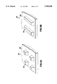
- FIG. 5A illustrates a first geometry for the light extraction tape according to the present invention
- FIG. 5B illustrates a second geometry for the light extraction tape according to the present invention
- FIG. 6A illustrates the formation of a negative mold for a light extraction tape
- FIG. 6B illustrates the formation of a light extraction tape from the negative mold of FIG. 6A
- FIG. 7 illustrates a process for forming a composite light extraction tape
- the present invention is applicable to a variety of systems and arrangements in which it is desired to extract light from a light guiding system, such as a waveguide.
- Light guiding systems are assumed to include small core and large core diameter optical fibers, planar optically guiding substrates, and other devices employing total internal reflection for guiding light from one point to another.
- the invention has been found to be particularly advantageous in applications where it is desired to extract light transversely from the side of a large core plastic optical fiber, rather than extracting light from a longitudinal end. While the present invention is not so limited, an understanding of various aspects of the invention is best gained through a discussion of various application examples operating in such an environment.
- a front extraction tape (FET) 22 is shown on the top surface of the optical fiber 14, at a region from which the cladding 18 has been removed.
- the FET 22 includes an outer portion 24 and at least one light coupling element 26.
- the refractive index of the light coupling element 26 is preferably the same or higher than the refractive index of the core 16 for coupling light out of the fiber 14.
- the light 10 may reflect by total internal reflection at reflecting surface 32 or may be reflected by a reflecting coating, for example a vapor-deposited metal coating provided on the reflecting surface 32.
- a reflecting coating for example a vapor-deposited metal coating provided on the reflecting surface 32.
- the light coupling element 26 is shown to have a trapezoidal shape having an input face 28 in optical contact with the core 16, it is understood that other shapes may be used for the light coupling element 26.
- the refractive index of the light coupling element 26 is preferably higher than or equal to the refractive index of the core 16 for extracting light from the core 16.
- the light coupling elements 26 are integrally formed with the outer portion 24 as a unitary structure. Consequently, there is no material interface between the light coupling element 26 and the outer portion 24.
- This first embodiment is preferably manufactured in a one-stage molding process.
- the material from which the FET 22 is manufactured is advantageously compressible and pliable, so that the input face 28 of each light coupling element 26 may conform so as to produce an optical contact with the core 16 under the application of slight pressure.
- An advantage of using a compressible material for the FET 22 is that the use of an index matching layer between the input face 28 and the core 16 may be avoided.
- prior art light extractors require the use of an index matching layer between the input face of the coupling prism and the waveguide core.
- the light extraction rate defined as the fraction of light in the core 16 coupled out per unit length and measured in % per cm, may be selected by the designer by varying the spacing between light coupling elements 26 and the size of the input surface 28. In general, the light extraction rate varies with the fraction of the surface area of the core 16 covered by the input faces 28 of the light coupling elements. Thus, the light extraction rate remains constant when the spacing between light coupling elements 26 and the area of each input face 28 are reduced by the same factor.
- the light extraction rate may be increased along the length of the optical fiber 14 so as to maintain a uniform light output along its length, even though the intensity of light within the fiber 14 reduces with distance.
- the designer may select a shape for the light coupling element 26 to produce the desired output direction and angular spread. It is also understood that the light coupling elements are preferably designed to have sufficient depth so that light passing out of the core 16 does not miss the reflecting surface 32, but is reflected by the reflecting surface 32 into the desired direction.
- the trapezoidal light coupling elements 26 may be provided with curved reflecting surfaces 32 so as to tailor the angular spread of the output light for selected applications.
- the FET 22 may employ a light coupling element 26 having a refractive index less than the refractive index of the core, but higher than the refractive index of the cladding.
- the critical angle associated with such a light coupling element, ⁇ 1 is larger than the critical angle associated with the cladding, ⁇ c .
- ⁇ 1 is larger than the critical angle associated with the cladding, ⁇ c .
- ⁇ c the critical angle associated with the cladding
- the light coupling element 26 in this case extracts only that portion of the light propagating through the core 16 at an angle between ⁇ c and ⁇ 1 , a more highly collimated output may be obtained from the FET 22 than when the refractive index of the light coupling element 26 is higher than or equal to the refractive index of the core 16.
- the FET 22 may be attached to the core 16 by a number of methods, including wrapping a cladding over the FET 22, using a heat-shrink cladding, and bonding the light coupling elements 26 to the core 16.
- the FET 22 may be flexible, so as to fit around a portion of the circumference of the core 16.
- FIG. 2 illustrates a second embodiment of the present invention, in which a composite FET 22 is formed by securing a light coupling element 26 directly to the lower surface of the outer portion 24.
- a thin layer of index matching agent 34, intermediate the input face 28 and the core 16, may be used to provide high quality optical coupling therebetween.
- the index matching agent 34 may be an optically transparent adhesive, such as an optical epoxy, which advantageously secures the FET 22 to the fiber 14.
- Light ray 36 passes from the core 16, passes through the layer of the index matching agent 34, reflects off a point near the top of reflecting surface 32, and exits through the outer portion 24.
- Light ray 38 is directed out of the core 16 by the FET 22 in a similar manner, but reflects off the lower portion of the reflecting surface 32.
- Light ray 40 passes into the index matching agent 34, but misses the light coupling element 26, and escapes. It is preferred to maintain the index matching agent 34 as thin as possible, or for the index matching agent 34 to preserve the shape of the input face 28, and thus reduce the amount of light lost in the manner of light ray 40.
- the refractive index of the index matching agent 34 may lie between the refractive index of the core 16 and the refractive index of the light coupling element 26 so as to reduce reflective losses.
- the refractive index of the index matching agent 34 may alternatively be higher than the refractive index of the core 16 in order to refract light away from the surface of the core 16, and thus reduce losses of the type shown for light ray 40.
- an adhesive index matching layer 34 is to coat the input surface 28 of the light coupling element with a monomer of the material used in the core 16. For example, if the core 16 is formed of an acrylate material, then an acrylate monomer may be applied to the input surface 28. Once the light coupling element 26 is placed in contact with the core 16, the monomer may then be cured, for example by illumination with ultraviolet (UV) light, so as to form a secure optical contact therebetween.
- UV ultraviolet
- An advantage of the second embodiment over prior art light extractors is that the FET 22 of the second embodiment allows the light coupling elements 26 and the outer portion 24 to be formed from different materials, while including at most only one layer of index matching agent 34.
- prior art extractors formed with components of different materials include two layers of adhesive. The first adhesive layer in the prior art extractor is between the light coupling prisms and the waveguide core, and the second adhesive layer is between the light coupling elements and the outer portion.
- FIG. 8 illustrates this problem, where a prior art light extractor including a prism 126 attached to a waveguide 116 by an adhesive layer 134. A second adhesive layer 135 attaches the prism 126 to a substrate 124. A portion of adhesive 136 has migrated on the reflective surface 132 of a prior art device.
- Light 137 incident at the area where the adhesive 136 is on the reflecting surface 132 is transmitted out of the light coupling element 126, unlike light ray 139 which reflects off the reflecting surface 132 in the desired direction. Furthermore, the prior art devices have higher optical losses due to the higher number of material interfaces and increased scattering and absorption.
- FIG. 3 illustrates a third embodiment of the invention where the refractive index of the outer portion 25 is lower than the refractive index of the core 16. Consequently, the outer portion 25 may also be used as a cladding.
- the light coupling elements 26 are preferably applied to the core 16 first, and then the outer portion 25 applied as a heat-shrinkable cladding so as to shrink around the core 16 and light coupling elements 26.
- the resulting outer portion 25 may contact the core 16 in portions intermediate the light coupling elements 26 to form a conventional cladding layer at these intermediate portions.
- the light coupling elements 26 may be applied to the core 16 using an adhesive layer of index matching agent 34, or using other methods as described herein. It is understood that alternative procedures for forming the fiber/FET structure of FIG. 3 may be used.
- the light coupling elements 26 may be integral with the outer portion 25 as a heat-shrinkable unit.
- FIGS. 4A and 4B show the effect of manufacturing the light coupling element 26 from a material which is elastic, or compressible.
- the light coupling element 26 has a convex shape, for example a portion of a sphere. If pressure is applied to the outer portion 24 in the direction shown by the arrow, the light coupling element 26 is pushed against the core 16 so as to increase the area of the input face 28 in contact with the core 16. Adjustment of the pressure on the FET 22 results in changing the area of the input face, 28, thus altering the fraction of light extracted from the core.
- the FET 22 may, therefore, be operable as a continuously variable pressure sensitive switch.
- the light coupling element 26 may be designed to produce different pressure-dependent characteristics having a portion of the input face which lies at a slope relative to the surface of the core 16.
- the spherical light coupling element 26 illustrated in FIGS. 4A and 4B may be manufactured from a relatively compressible material, thus allowing a large, continuous variation in the area of the input face 28. The variation in input face area is reduced for material having a lower compressibility.
- Other shapes may be employed for the light coupling element.
- FIG. 4C illustrates a light coupling element 26 essentially trapezoidal in shape with a convex portion on the input face 28. Increasing the pressure applied to this light coupling element 26 results in a continuous increase in the input face area until the whole input face is pressed against the core 16.
- FIG. 4D Another alternative shape for the light coupling element 26 is illustrated in FIG. 4D, where the shape is essentially trapezoidal, but where the input face 28 lies at a small angle relative to the core 16.
- Other pressure-dependent characteristics may be selected by a judicious choice of the material properties and the shape of the light coupling element 26.
- a periodic array of pressure sensitive light coupling elements may be designed to have minimal contact area in the absence of pressure and a large contact area when pressure is exerted. If the light coupling elements 26 are made of a suitably deformable material, or a suitable transparent adhesive is applied between the input faces 28 and the core 16, then the contacting area of the pressure sensitive light coupling elements 26 may be adjusted and set permanently. Such a one-time adjustment is advantageous for field installations and certain security applications.
- FIGS. 5A and 5B illustrate alternative arrangements for implementing the invention.
- FIG. 5A illustrates an FET 22 where the light coupling elements 26 are implemented in an array of individual trapezoidal prisms. Such an implementation is advantageous where the application requirements are for low extraction rate with high light coupling element density, as would be the case, for example, where the light output from the fiber 14 is required to be uniform, but over a relatively long length of fiber.
- FIG. 5B illustrates an FET 22 where the light coupling elements 26 are implemented as ribs having a trapezoidal cross-section. Such an implementation is advantageous where the application requires a high extraction rate.
- FIG. 6 illustrates a preferred method of manufacturing the first embodiment of the FET 22.
- FIG. 6A shows a positive mold 50 having a predetermined geometric structure corresponding to the FET 22.
- a detachable resin is brought into contact with the positive mold 50 and cured at normal temperature and detached to form a negative mold 52.
- Examples of the detachable resin include templating silicone SE9555 manufactured by Toray Dow Corning Co., Ltd.
- a preliminary component comprising a monomer component containing isooctyl acrylate, acrylic acid and a photoinitiator component in predetermined proportions is charged in a stirring device, and is subjected to ultraviolet polymerization with stirring. At this stage, a partial polymerization is carried out so that the viscosity ranges from 100 to 100,000 cps to prepare a partially polymerized syrup.
- a predetermined amount of a crosslinking agent monomer, 1,6-hexanediol diacrylate, and additional photoinitiator are added to the syrup, and the resultant is mixed uniformly to prepare a precursor composition of the FET 22.
- the interior of the stirring device is generally purged with a non-reacting gas such as nitrogen gas, etc.
- Such a polymerization reaction generally does not include heating.
- An example of the syrup includes a mixture of 90 parts of isooctyl acrylate, 10 parts of acrylic acid and 0.1 part of photoinitiator. 1 part of 1,6-hexanediol diacrylate and 0.2 parts of additional photoinitiator are added to the syrup after partial polymerization.
- the next stage includes bringing the precursor composition 54 into contact with the negative mold 52, and the composition is covered with a transparent film 56.
- the precursor composition 54 is cured by UV cross-linking. UV light transmitted by the film 56 illuminates the precursor composition 54 to complete curing and, after the negative mold 52 and film 56 have been removed, a sheet of compressible FET 22 is obtained.
- a UV fluence ranging from 100 mJ cm -2 to 1,000 mJ cm -2 , and having a wavelength ranging from 300 nm to 400 nm is preferably used for curing.
- the transparent film 56 is used for barring oxygen and making the upper surface of the outer portion 57 flat.
- the film 56 may also be used as a transparent substrate fixed to the outer portion 24.
- a flexible plastic, such as polyester may be used for the film 56.
- the thickness of the outer portion 58 may be controlled by pouring an excess of the precursor composition 54 into the negative mold 52 and the film 56 laminated on top.
- the mold 52, precursor 54 and film 56 are passed through a knife coater together, where the gap of the knife coater is set at a predetermined distance. Excess precursor composition is squeezed out at the sides, so that the thickness of the outer portion 58 is adjusted to the desired value.
- the positive mold 50 may be formed from a sanded glass plate, or a re-usable negative mold may be formed from, for example a metal coated with a releasing agent.
- the releasing agent may be a fluorinated resin, such as polytetrafluorethylene.
- the FET 22 shown in FIG. 2 has a composite structure, where the light coupling elements 26 are secured to a substrate acting as an outer portion 24.
- the outer portion 24 is typically formed from a polyurethane film.
- the light coupling elements 26 may be formed from transparent, curable materials, including acrylates, which are cured by exposure to ultraviolet light 68, or urethane or silicone adhesives, which are cured under heat.
- FIG. 7 illustrates a method of manufacturing the second embodiment of the FET 22 using a UV curable acrylate.
- a first drum 60 dispenses a substrate sheet 62, typically polyurethane, to a first pinch drum 64, where the sheet 62 is pinched between the first pinch roller 64 and a molding drum 66.
- a second pinch roller 68 is located at approximately 180° around the molding drum 66 from the first pinch roller 64, where the sheet 62 is peeled off the molding drum 66.
- the first and second pinch rollers 64 and 68 hold the sheet 62 therebetween in close contact with the molding drum 66.
- a second drum 70 receives the sheet 62 after it has been peeled off the molding drum 66.
- a dispenser 72 dispenses a flowable, transparent, UV curable resin 74 so as to flow between the sheet 62 and the molding drum 66.
- the sheet 62 between the first and second pinch rollers 64 and 68 molds the resin by holding it against a molding surface 76 on the molding drum 66.
- the molding surface 76 is shaped to mold the light coupling elements 26.
- a first UV light source 78 illuminates the resin 74 as it passes between the first and second pinch rollers 64 and 68, so as to achieve at least partial curing of the resin 74.
- the resin 74 adheres to the sheet 62 to form a composite FET 82 which is peeled off the molding drum 66 at the second pinch roller 68.
- a second UV light source 84 may be used for further curing.
- the FET 22 may be removed from fabrication before the material of the light coupling elements 26 is completely cured and retains a degree of flowability.
- the FET 22 may be applied to the core 16 so as to form optical interfaces 30 between the light coupling elements 26 and the core 16, and then the curing process completed in place.
- a front extraction tape has been described which enables a user to extract light transversely from a waveguide.
- the front extraction tape is simpler to manufacture and incurs less reflective loss than prior art waveguide output extractors. Additionally, it may be implemented using a compressible material, thus permitting the tape to produce a pressure-sensitive output.
Abstract
Description
Claims (30)
Priority Applications (6)
| Application Number | Priority Date | Filing Date | Title |
|---|---|---|---|
| US08/755,767 US5995690A (en) | 1996-11-21 | 1996-11-21 | Front light extraction film for light guiding systems and method of manufacture |
| JP52362798A JP2001504598A (en) | 1996-11-21 | 1997-09-08 | Forward light extraction film for light guide device and method of manufacturing the same |
| AU42571/97A AU4257197A (en) | 1996-11-21 | 1997-09-08 | Front light extraction film for light guiding systems and method of manufacture |
| EP97940893A EP1025388A1 (en) | 1996-11-21 | 1997-09-08 | Front light extraction film for light guiding systems and method of manufacture |
| KR1019990704374A KR20000053350A (en) | 1996-11-21 | 1997-09-08 | Front light extraction film for light guiding systems and method of manufacture |
| PCT/US1997/015791 WO1998022749A1 (en) | 1996-11-21 | 1997-09-08 | Front light extraction film for light guiding systems and method of manufacture |
Applications Claiming Priority (1)
| Application Number | Priority Date | Filing Date | Title |
|---|---|---|---|
| US08/755,767 US5995690A (en) | 1996-11-21 | 1996-11-21 | Front light extraction film for light guiding systems and method of manufacture |
Publications (1)
| Publication Number | Publication Date |
|---|---|
| US5995690A true US5995690A (en) | 1999-11-30 |
Family
ID=25040576
Family Applications (1)
| Application Number | Title | Priority Date | Filing Date |
|---|---|---|---|
| US08/755,767 Expired - Lifetime US5995690A (en) | 1996-11-21 | 1996-11-21 | Front light extraction film for light guiding systems and method of manufacture |
Country Status (6)
| Country | Link |
|---|---|
| US (1) | US5995690A (en) |
| EP (1) | EP1025388A1 (en) |
| JP (1) | JP2001504598A (en) |
| KR (1) | KR20000053350A (en) |
| AU (1) | AU4257197A (en) |
| WO (1) | WO1998022749A1 (en) |
Cited By (77)
| Publication number | Priority date | Publication date | Assignee | Title |
|---|---|---|---|---|
| US20020051866A1 (en) * | 2000-08-18 | 2002-05-02 | Reflexite Corporation | Differentially cured materials and process for forming same |
| US6461031B1 (en) | 1998-03-27 | 2002-10-08 | 3M Innovative Properties Company | Spot light fiber and illuminating apparatus |
| WO2002081965A1 (en) | 2001-04-06 | 2002-10-17 | 3M Innovative Properties Company | Frontlit display |
| US6535667B1 (en) | 2001-12-31 | 2003-03-18 | 3M Innovative Properties Company | Light fiber comprising continuous outer cladding and method of making |
| US20030133301A1 (en) * | 2002-01-15 | 2003-07-17 | Reflexite Corporation | Grooved optical microstructure light collimating films |
| US6597834B1 (en) | 1998-03-13 | 2003-07-22 | 3M Innovative Properties Company | Optical fiber linear light source |
| US20030146441A1 (en) * | 2001-05-07 | 2003-08-07 | Anritsu Corporation | Semiconductor light receiving device for repeatedly propagating incident light in light absorption layer and method for manufacturing the same |
| US20030156431A1 (en) * | 2001-12-31 | 2003-08-21 | Gozum John E. | Illumination device |
| US6700716B2 (en) * | 1999-05-20 | 2004-03-02 | Zumiobel Staff Gmbh | Optical element with a microprism structure for deflecting light beams |
| US20040084813A1 (en) * | 2002-10-31 | 2004-05-06 | Prague David J. | Method of molding decorative elements for consumer packaging |
| EP1120600B1 (en) * | 1999-12-01 | 2004-05-12 | Siteco Beleuchtungstechnik GmbH | Light guide lamp with linear prismatic structure |
| US6738051B2 (en) | 2001-04-06 | 2004-05-18 | 3M Innovative Properties Company | Frontlit illuminated touch panel |
| US20040169928A1 (en) * | 2002-05-15 | 2004-09-02 | Reflexite Corporation | Optical structures |
| US20040190102A1 (en) * | 2000-08-18 | 2004-09-30 | Mullen Patrick W. | Differentially-cured materials and process for forming same |
| US20040246599A1 (en) * | 2003-05-02 | 2004-12-09 | Reflexite Corporation | Light-redirecting optical structures |
| US20050141243A1 (en) * | 2000-08-18 | 2005-06-30 | Reflexite Corporation | Differentially-cured materials and process for forming same |
| US20050147372A1 (en) * | 2003-12-29 | 2005-07-07 | Eastman Kodak Company | Wave-guided optical indicator |
| US20050265029A1 (en) * | 2004-06-01 | 2005-12-01 | 3M Innovative Properties Company | Led array systems |
| US20060044819A1 (en) * | 2004-08-31 | 2006-03-02 | An Hong Bul | Lightpipe with multiple projections |
| US7046906B1 (en) * | 2005-01-21 | 2006-05-16 | Inventec Corporation | Light guide pillar |
| US20060145077A1 (en) * | 2004-12-30 | 2006-07-06 | Dongbu-Anam Semiconductor | Image sensor using optical fiber |
| US20060290842A1 (en) * | 2005-06-24 | 2006-12-28 | Epstein Kenneth A | Optical element for lateral light spreading in back-lit displays and system using same |
| US20060291238A1 (en) * | 2005-06-24 | 2006-12-28 | Epstein Kenneth A | Color mixing illumination light unit and system using same |
| US20060290845A1 (en) * | 2005-06-24 | 2006-12-28 | Hebrink Timothy J | Polarization sensitive illumination element and system using same |
| US20060290843A1 (en) * | 2005-06-24 | 2006-12-28 | Epstein Kenneth A | Illumination element and system using same |
| US20060290844A1 (en) * | 2005-06-24 | 2006-12-28 | Epstein Kenneth A | Optical element for lateral light spreading in edge-lit displays and system using same |
| US20070041701A1 (en) * | 2005-08-18 | 2007-02-22 | Tsinghua University | Light guide plate and a backlight system |
| US20070081110A1 (en) * | 2005-10-10 | 2007-04-12 | Eastman Kodak Company | Backlight unit with linearly reduced divergence |
| US20070230213A1 (en) * | 2006-03-28 | 2007-10-04 | Samsung Electronics Co., Ltd. | Backlight having all-in-one type light guide plate and method of manufacturing all-in-one type light guide plate |
| US20070242334A1 (en) * | 2006-01-24 | 2007-10-18 | Uni-Pixel Displays, Inc. | Corner-Cube Retroreflectors for Displays |
| WO2009011961A2 (en) | 2007-07-13 | 2009-01-22 | 3M Innovative Properties Company | Light extraction film for organic light emitting diode display devices |
| US20090103009A1 (en) * | 2005-08-26 | 2009-04-23 | Tohoku University | Liquid crystal display and light guide plate |
| US20090147361A1 (en) * | 2007-12-07 | 2009-06-11 | 3M Innovative Properties Company | Microreplicated films having diffractive features on macro-scale features |
| US20090316058A1 (en) * | 2008-06-18 | 2009-12-24 | 3M Innovative Properties Company | Films enabling autostereoscopy |
| US20100085773A1 (en) * | 2009-01-02 | 2010-04-08 | Brian Edward Richardson | Optic system light guide with controlled output |
| US20100142222A1 (en) * | 2008-12-04 | 2010-06-10 | World Properties, Inc. | Light guide with refractive layer |
| WO2010051229A3 (en) * | 2008-10-31 | 2010-07-22 | 3M Innovative Properties Company | Light extraction film with high index backfill layer and passivation layer |
| US20100214208A1 (en) * | 2005-12-27 | 2010-08-26 | Tatsuo Itoh | Planar lighting device and liquid crystal display device |
| US20100220492A1 (en) * | 2009-06-11 | 2010-09-02 | Brian Edward Richardson | Optical system with reflectors and light pipes |
| US20100315836A1 (en) * | 2009-06-11 | 2010-12-16 | Brian Edward Richardson | Flat panel optical display system with highly controlled output |
| US20100315802A1 (en) * | 2009-06-11 | 2010-12-16 | Brian Edward Richardson | Optical system for a Light Emitting Diode with collection, conduction, phosphor directing, and output means |
| US20100328748A1 (en) * | 2005-12-09 | 2010-12-30 | Brian Edward Richardson | TIR Light Valve |
| CN101960210A (en) * | 2008-03-07 | 2011-01-26 | 皇家飞利浦电子股份有限公司 | Lighting system with removable light extracting member |
| US20110116284A1 (en) * | 2009-11-18 | 2011-05-19 | Brian Edward Richardson | Internal Collecting Reflector Optics For LEDs |
| US7957621B2 (en) | 2008-12-17 | 2011-06-07 | 3M Innovative Properties Company | Light extraction film with nanoparticle coatings |
| WO2011078989A1 (en) | 2009-12-21 | 2011-06-30 | 3M Innovative Properties Company | Optical films enabling autostereoscopy |
| US20110235362A1 (en) * | 2010-03-29 | 2011-09-29 | Hon Hai Precision Industry Co., Ltd. | Light concentration device and related backlight module |
| US8179034B2 (en) | 2007-07-13 | 2012-05-15 | 3M Innovative Properties Company | Light extraction film for organic light emitting diode display and lighting devices |
| US8272770B2 (en) | 2009-01-02 | 2012-09-25 | Rambus International Ltd. | TIR switched flat panel display |
| US20130062798A1 (en) * | 2010-02-01 | 2013-03-14 | Kung-Li Deng | Method for manufacturing a modified optical fiber |
| WO2013052319A1 (en) * | 2011-10-05 | 2013-04-11 | 3M Innovative Properties Company | Microstructured transfer tapes |
| US20140041796A1 (en) * | 2010-08-09 | 2014-02-13 | Dexerials Corporation | Optical element, method of manufacturing optical element, illumination device, window member, and fitting |
| US8827531B2 (en) | 2011-05-13 | 2014-09-09 | Rambus Delaware Llc | Lighting assembly |
| DE202014103304U1 (en) * | 2014-07-17 | 2015-10-21 | Zumtobel Lighting Gmbh | Luminaire assembly and thus equipped lighting device |
| WO2015191949A1 (en) | 2014-06-13 | 2015-12-17 | 3M Innovative Properties Company | Optical stacks for sparkle reduction |
| US9291340B2 (en) | 2013-10-23 | 2016-03-22 | Rambus Delaware Llc | Lighting assembly having n-fold rotational symmetry |
| US9308051B2 (en) | 2011-11-15 | 2016-04-12 | Smiths Medical Asd, Inc. | Illuminated tubing set |
| US9308323B2 (en) | 2011-11-15 | 2016-04-12 | Smiths Medical Asd, Inc. | Systems and methods for illuminated medical tubing detection and management indicating a characteristic of at least one infusion pump |
| DE202015104088U1 (en) * | 2015-08-05 | 2016-11-09 | Zumtobel Lighting Gmbh | Luminaire optics and luminaire comprising the luminaire optics |
| US9581755B2 (en) | 2013-10-14 | 2017-02-28 | E Ink Holdings Inc. | Reflective display apparatus and manufacturing method of reflective display apparatus |
| WO2017205174A1 (en) | 2016-05-27 | 2017-11-30 | 3M Innovative Properties Company | Oled display with improved color uniformity |
| US20170363795A1 (en) * | 2016-06-17 | 2017-12-21 | Cree, Inc. | Bonded optical systems and applications thereof |
| US9862124B2 (en) | 2014-07-18 | 2018-01-09 | 3M Innovative Properties Company | Multilayer optical adhesives and methods of making same |
| US9919339B2 (en) | 2014-06-18 | 2018-03-20 | 3M Innovation Properties Company | Optical film |
| DE102016218712A1 (en) | 2016-09-28 | 2018-03-29 | Zumtobel Lighting Gmbh | Optical system for a luminaire, as well as a luminaire |
| US9995944B2 (en) | 2014-06-13 | 2018-06-12 | 3M Innovative Properties Company | Optical stacks for sparkle reduction |
| US20180203299A1 (en) * | 2017-01-17 | 2018-07-19 | Boe Technology Group Co., Ltd. | Backlight module, display panel and display device |
| US10135033B2 (en) | 2016-10-20 | 2018-11-20 | Corning Incorporated | Directional light extraction for organic light emitting diode (OLED) illumination devices |
| WO2018220473A1 (en) | 2017-06-02 | 2018-12-06 | 3M Innovative Properties Company | Optical film and optical system |
| WO2019202554A1 (en) | 2018-04-20 | 2019-10-24 | 3M Innovative Properties Company | Headset and head-mounted display |
| US10756306B2 (en) | 2016-10-28 | 2020-08-25 | 3M Innovative Properties Company | Nanostructured article |
| US10761320B2 (en) | 2015-12-09 | 2020-09-01 | 3M Innovative Properties Company | Optical stack including a grating |
| US10775547B2 (en) | 2017-03-31 | 2020-09-15 | 3M Innovation Properties Company | Lightguide |
| US11175533B2 (en) | 2018-05-03 | 2021-11-16 | 3M Innovative Properties Company | Light redirecting film, backlight, and display system |
| US20220003926A1 (en) * | 2016-05-06 | 2022-01-06 | Ideal Industries Lighting Llc | Waveguide-based light sources with dynamic beam shaping |
| WO2022233207A1 (en) * | 2021-05-06 | 2022-11-10 | 苏州晶智科技有限公司 | Surface light source apparatus and flat panel display apparatus |
| US11708510B2 (en) | 2016-01-15 | 2023-07-25 | 3M Innovative Properties Company | Optical adhesive |
Families Citing this family (10)
| Publication number | Priority date | Publication date | Assignee | Title |
|---|---|---|---|---|
| JPH11295530A (en) * | 1998-03-13 | 1999-10-29 | Minnesota Mining & Mfg Co <3M> | Optical fiber |
| US6039553A (en) * | 1998-12-02 | 2000-03-21 | 3M Innovative Properties Company | Apparatus for molding light extraction structures onto a light guide |
| US6033604A (en) * | 1998-12-02 | 2000-03-07 | 3M Innovative Properties Company | Method for molding light extraction structures onto a light guide |
| DE102005028659B3 (en) * | 2005-06-15 | 2006-06-08 | Siemens Ag | Optical fiber tape producing method for motor vehicle, involves continuously producing tape such that fibers are controlled between process step of fiber surface treatment and subsequent process step to produce tape in torsion free manner |
| JP2007272070A (en) * | 2006-03-31 | 2007-10-18 | Hamamatsu Photonics Kk | Leakage optical fiber and method for manufacturing leakage optical fiber |
| US20080285304A1 (en) | 2007-05-18 | 2008-11-20 | Rankin Jr Charles M | Light extraction film system |
| KR20160030202A (en) | 2013-07-02 | 2016-03-16 | 쓰리엠 이노베이티브 프로퍼티즈 컴파니 | Flat light guide |
| DE102016118884A1 (en) * | 2016-10-05 | 2018-04-05 | Temicon Gmbh | Light deflecting device, lighting device and use |
| KR102023109B1 (en) * | 2017-09-06 | 2019-09-19 | 국민대학교산학협력단 | Lateral emitting optical fiber and manufacturing method for thereof |
| JP7023831B2 (en) * | 2018-12-26 | 2022-02-22 | 三菱電線工業株式会社 | Side emission type optical fiber |
Citations (15)
| Publication number | Priority date | Publication date | Assignee | Title |
|---|---|---|---|---|
| US4052120A (en) * | 1975-02-26 | 1977-10-04 | Erwin Sick Optik-Elektronik | Optical apparatus for producing a light curtain |
| US4975807A (en) * | 1987-06-29 | 1990-12-04 | Nippon Seiki | Indicating apparatus |
| US5175030A (en) * | 1989-02-10 | 1992-12-29 | Minnesota Mining And Manufacturing Company | Microstructure-bearing composite plastic articles and method of making |
| US5183597A (en) * | 1989-02-10 | 1993-02-02 | Minnesota Mining And Manufacturing Company | Method of molding microstructure bearing composite plastic articles |
| WO1994020871A1 (en) * | 1993-03-11 | 1994-09-15 | Nioptics Corporation | Tapered multilayer luminaire devices |
| US5396350A (en) * | 1993-11-05 | 1995-03-07 | Alliedsignal Inc. | Backlighting apparatus employing an array of microprisms |
| WO1995011464A2 (en) * | 1993-10-20 | 1995-04-27 | Minnesota Mining And Manufacturing Company | Ultra-flexible retroreflective cube corner composite sheetings and methods of manufacture |
| US5428468A (en) * | 1993-11-05 | 1995-06-27 | Alliedsignal Inc. | Illumination system employing an array of microprisms |
| US5462700A (en) * | 1993-11-08 | 1995-10-31 | Alliedsignal Inc. | Process for making an array of tapered photopolymerized waveguides |
| US5506929A (en) * | 1994-10-19 | 1996-04-09 | Clio Technologies, Inc. | Light expanding system for producing a linear or planar light beam from a point-like light source |
| US5521725A (en) * | 1993-11-05 | 1996-05-28 | Alliedsignal Inc. | Illumination system employing an array of microprisms |
| US5555329A (en) * | 1993-11-05 | 1996-09-10 | Alliesignal Inc. | Light directing optical structure |
| WO1997008490A1 (en) * | 1995-08-23 | 1997-03-06 | Minnesota Mining And Manufacturing Company | Structured surface light extraction overlay and illumination system |
| WO1997027423A1 (en) * | 1996-01-24 | 1997-07-31 | Minnesota Mining And Manufacturing Company | Conspicuity marking system |
| US5696865A (en) * | 1995-02-17 | 1997-12-09 | Alliedsignal Inc. | Optical waveguide having two or more refractive indices and method of manufacturing same |
-
1996
- 1996-11-21 US US08/755,767 patent/US5995690A/en not_active Expired - Lifetime
-
1997
- 1997-09-08 AU AU42571/97A patent/AU4257197A/en not_active Abandoned
- 1997-09-08 JP JP52362798A patent/JP2001504598A/en active Pending
- 1997-09-08 EP EP97940893A patent/EP1025388A1/en not_active Withdrawn
- 1997-09-08 WO PCT/US1997/015791 patent/WO1998022749A1/en not_active Application Discontinuation
- 1997-09-08 KR KR1019990704374A patent/KR20000053350A/en not_active Application Discontinuation
Patent Citations (15)
| Publication number | Priority date | Publication date | Assignee | Title |
|---|---|---|---|---|
| US4052120A (en) * | 1975-02-26 | 1977-10-04 | Erwin Sick Optik-Elektronik | Optical apparatus for producing a light curtain |
| US4975807A (en) * | 1987-06-29 | 1990-12-04 | Nippon Seiki | Indicating apparatus |
| US5175030A (en) * | 1989-02-10 | 1992-12-29 | Minnesota Mining And Manufacturing Company | Microstructure-bearing composite plastic articles and method of making |
| US5183597A (en) * | 1989-02-10 | 1993-02-02 | Minnesota Mining And Manufacturing Company | Method of molding microstructure bearing composite plastic articles |
| WO1994020871A1 (en) * | 1993-03-11 | 1994-09-15 | Nioptics Corporation | Tapered multilayer luminaire devices |
| WO1995011464A2 (en) * | 1993-10-20 | 1995-04-27 | Minnesota Mining And Manufacturing Company | Ultra-flexible retroreflective cube corner composite sheetings and methods of manufacture |
| US5396350A (en) * | 1993-11-05 | 1995-03-07 | Alliedsignal Inc. | Backlighting apparatus employing an array of microprisms |
| US5428468A (en) * | 1993-11-05 | 1995-06-27 | Alliedsignal Inc. | Illumination system employing an array of microprisms |
| US5521725A (en) * | 1993-11-05 | 1996-05-28 | Alliedsignal Inc. | Illumination system employing an array of microprisms |
| US5555329A (en) * | 1993-11-05 | 1996-09-10 | Alliesignal Inc. | Light directing optical structure |
| US5462700A (en) * | 1993-11-08 | 1995-10-31 | Alliedsignal Inc. | Process for making an array of tapered photopolymerized waveguides |
| US5506929A (en) * | 1994-10-19 | 1996-04-09 | Clio Technologies, Inc. | Light expanding system for producing a linear or planar light beam from a point-like light source |
| US5696865A (en) * | 1995-02-17 | 1997-12-09 | Alliedsignal Inc. | Optical waveguide having two or more refractive indices and method of manufacturing same |
| WO1997008490A1 (en) * | 1995-08-23 | 1997-03-06 | Minnesota Mining And Manufacturing Company | Structured surface light extraction overlay and illumination system |
| WO1997027423A1 (en) * | 1996-01-24 | 1997-07-31 | Minnesota Mining And Manufacturing Company | Conspicuity marking system |
Cited By (126)
| Publication number | Priority date | Publication date | Assignee | Title |
|---|---|---|---|---|
| US6597834B1 (en) | 1998-03-13 | 2003-07-22 | 3M Innovative Properties Company | Optical fiber linear light source |
| US6461031B1 (en) | 1998-03-27 | 2002-10-08 | 3M Innovative Properties Company | Spot light fiber and illuminating apparatus |
| US6700716B2 (en) * | 1999-05-20 | 2004-03-02 | Zumiobel Staff Gmbh | Optical element with a microprism structure for deflecting light beams |
| EP1120600B1 (en) * | 1999-12-01 | 2004-05-12 | Siteco Beleuchtungstechnik GmbH | Light guide lamp with linear prismatic structure |
| US20020051866A1 (en) * | 2000-08-18 | 2002-05-02 | Reflexite Corporation | Differentially cured materials and process for forming same |
| US7517205B2 (en) | 2000-08-18 | 2009-04-14 | Reflexite Corporation | Differentially cured materials and process for forming same |
| US20070253072A1 (en) * | 2000-08-18 | 2007-11-01 | Mullen Patrick W | Differentially-cured materials and process for forming same |
| US20040190102A1 (en) * | 2000-08-18 | 2004-09-30 | Mullen Patrick W. | Differentially-cured materials and process for forming same |
| US20050141243A1 (en) * | 2000-08-18 | 2005-06-30 | Reflexite Corporation | Differentially-cured materials and process for forming same |
| US7250122B2 (en) | 2000-08-18 | 2007-07-31 | Reflexite Corporation | Differentially cured materials and process for forming same |
| US7230764B2 (en) | 2000-08-18 | 2007-06-12 | Reflexite Corporation | Differentially-cured materials and process for forming same |
| US7253809B2 (en) | 2001-04-06 | 2007-08-07 | 3M Innovative Properties Company | Frontlit illuminated touch panel |
| US6738051B2 (en) | 2001-04-06 | 2004-05-18 | 3M Innovative Properties Company | Frontlit illuminated touch panel |
| US6592234B2 (en) | 2001-04-06 | 2003-07-15 | 3M Innovative Properties Company | Frontlit display |
| US20060132453A1 (en) * | 2001-04-06 | 2006-06-22 | 3M Innovative Properties Company | Frontlit illuminated touch panel |
| WO2002081965A1 (en) | 2001-04-06 | 2002-10-17 | 3M Innovative Properties Company | Frontlit display |
| US7071524B2 (en) * | 2001-05-07 | 2006-07-04 | Anristsu Corporation | Semiconductor light receiving device for repeatedly propagating incident light in light absorption layer and method for manufacturing the same |
| US20030146441A1 (en) * | 2001-05-07 | 2003-08-07 | Anritsu Corporation | Semiconductor light receiving device for repeatedly propagating incident light in light absorption layer and method for manufacturing the same |
| US6799880B2 (en) | 2001-12-31 | 2004-10-05 | 3M Innovative Properties Company | Illumination device |
| US6535667B1 (en) | 2001-12-31 | 2003-03-18 | 3M Innovative Properties Company | Light fiber comprising continuous outer cladding and method of making |
| US20030156431A1 (en) * | 2001-12-31 | 2003-08-21 | Gozum John E. | Illumination device |
| US6880946B2 (en) | 2002-01-15 | 2005-04-19 | Reflexite Corporation | Grooved optical microstructure light collimating films |
| US20030133301A1 (en) * | 2002-01-15 | 2003-07-17 | Reflexite Corporation | Grooved optical microstructure light collimating films |
| US20040169928A1 (en) * | 2002-05-15 | 2004-09-02 | Reflexite Corporation | Optical structures |
| US7364314B2 (en) | 2002-05-15 | 2008-04-29 | Reflexite Corporation | Optical structures |
| US20040084813A1 (en) * | 2002-10-31 | 2004-05-06 | Prague David J. | Method of molding decorative elements for consumer packaging |
| US7223360B2 (en) * | 2002-10-31 | 2007-05-29 | Rii Acquisition Corp. | Method of molding decorative elements for consumer packaging |
| US20040246599A1 (en) * | 2003-05-02 | 2004-12-09 | Reflexite Corporation | Light-redirecting optical structures |
| US7330315B2 (en) | 2003-05-02 | 2008-02-12 | Reflexite Corporation | Light-redirecting optical structures |
| US20050147372A1 (en) * | 2003-12-29 | 2005-07-07 | Eastman Kodak Company | Wave-guided optical indicator |
| US7058272B2 (en) * | 2003-12-29 | 2006-06-06 | Eastman Kodak Company | Wave-guided optical indicator |
| US8246220B2 (en) | 2004-06-01 | 2012-08-21 | 3M Innovative Properties Company | LED array systems |
| US7997771B2 (en) | 2004-06-01 | 2011-08-16 | 3M Innovative Properties Company | LED array systems |
| US20050265029A1 (en) * | 2004-06-01 | 2005-12-01 | 3M Innovative Properties Company | Led array systems |
| US20060044819A1 (en) * | 2004-08-31 | 2006-03-02 | An Hong Bul | Lightpipe with multiple projections |
| US7209627B2 (en) * | 2004-08-31 | 2007-04-24 | Hewlett-Packard Development Company, L.P. | Lightpipe with multiple projections |
| US20060145077A1 (en) * | 2004-12-30 | 2006-07-06 | Dongbu-Anam Semiconductor | Image sensor using optical fiber |
| US7046906B1 (en) * | 2005-01-21 | 2006-05-16 | Inventec Corporation | Light guide pillar |
| US20060290845A1 (en) * | 2005-06-24 | 2006-12-28 | Hebrink Timothy J | Polarization sensitive illumination element and system using same |
| US20060291238A1 (en) * | 2005-06-24 | 2006-12-28 | Epstein Kenneth A | Color mixing illumination light unit and system using same |
| US8023065B2 (en) | 2005-06-24 | 2011-09-20 | 3M Innovative Properties Company | Optical element for lateral light spreading in edge-lit displays and system using same |
| US20060290843A1 (en) * | 2005-06-24 | 2006-12-28 | Epstein Kenneth A | Illumination element and system using same |
| US7322731B2 (en) | 2005-06-24 | 2008-01-29 | 3M Innovative Properties Company | Color mixing illumination light unit and system using same |
| US20060290842A1 (en) * | 2005-06-24 | 2006-12-28 | Epstein Kenneth A | Optical element for lateral light spreading in back-lit displays and system using same |
| US7903194B2 (en) | 2005-06-24 | 2011-03-08 | 3M Innovative Properties Company | Optical element for lateral light spreading in back-lit displays and system using same |
| US20060290844A1 (en) * | 2005-06-24 | 2006-12-28 | Epstein Kenneth A | Optical element for lateral light spreading in edge-lit displays and system using same |
| US20070041701A1 (en) * | 2005-08-18 | 2007-02-22 | Tsinghua University | Light guide plate and a backlight system |
| US20090103009A1 (en) * | 2005-08-26 | 2009-04-23 | Tohoku University | Liquid crystal display and light guide plate |
| US8130340B2 (en) | 2005-08-26 | 2012-03-06 | Tohoku University | Liquid crystal display and light guide plate |
| US20070081110A1 (en) * | 2005-10-10 | 2007-04-12 | Eastman Kodak Company | Backlight unit with linearly reduced divergence |
| US7663712B2 (en) * | 2005-10-10 | 2010-02-16 | Skc Haas Display Films Co., Ltd. | Backlight unit with linearly reduced divergence having the width of an output aperture vary over the length of a light divergence reduction structure |
| US20100328748A1 (en) * | 2005-12-09 | 2010-12-30 | Brian Edward Richardson | TIR Light Valve |
| US20100214208A1 (en) * | 2005-12-27 | 2010-08-26 | Tatsuo Itoh | Planar lighting device and liquid crystal display device |
| US20070242334A1 (en) * | 2006-01-24 | 2007-10-18 | Uni-Pixel Displays, Inc. | Corner-Cube Retroreflectors for Displays |
| US7450799B2 (en) * | 2006-01-24 | 2008-11-11 | Uni-Pixel Displays, Inc. | Corner-cube retroreflectors for displays |
| US7985533B2 (en) | 2006-03-28 | 2011-07-26 | Samsung Electronics Co., Ltd. | Backlight having all-in-one type light guide plate and method of manufacturing all-in-one type light guide plate |
| US7720347B2 (en) * | 2006-03-28 | 2010-05-18 | Samsung Electronics Co., Ltd. | Backlight having all-in-one type light guide plate and method of manufacturing all-in-one type light guide plate |
| US20070230213A1 (en) * | 2006-03-28 | 2007-10-04 | Samsung Electronics Co., Ltd. | Backlight having all-in-one type light guide plate and method of manufacturing all-in-one type light guide plate |
| US20100181287A1 (en) * | 2006-03-28 | 2010-07-22 | Samsung Electronics Co., Ltd. | Backlight having all-in-one type light guide plate and method of manufacturing all-in-one type light guide plate |
| US8298032B2 (en) | 2007-07-13 | 2012-10-30 | 3M Innovative Properties Company | Methods for providing light extraction films on organic light emitting diode devices |
| US8179034B2 (en) | 2007-07-13 | 2012-05-15 | 3M Innovative Properties Company | Light extraction film for organic light emitting diode display and lighting devices |
| WO2009011961A3 (en) * | 2007-07-13 | 2009-03-19 | 3M Innovative Properties Co | Light extraction film for organic light emitting diode display devices |
| WO2009011961A2 (en) | 2007-07-13 | 2009-01-22 | 3M Innovative Properties Company | Light extraction film for organic light emitting diode display devices |
| US20090147361A1 (en) * | 2007-12-07 | 2009-06-11 | 3M Innovative Properties Company | Microreplicated films having diffractive features on macro-scale features |
| CN101960210A (en) * | 2008-03-07 | 2011-01-26 | 皇家飞利浦电子股份有限公司 | Lighting system with removable light extracting member |
| US20090316058A1 (en) * | 2008-06-18 | 2009-12-24 | 3M Innovative Properties Company | Films enabling autostereoscopy |
| US8068187B2 (en) | 2008-06-18 | 2011-11-29 | 3M Innovative Properties Company | Stereoscopic 3D liquid crystal display apparatus having a double sided prism film comprising cylindrical lenses and non-contiguous prisms |
| WO2010051229A3 (en) * | 2008-10-31 | 2010-07-22 | 3M Innovative Properties Company | Light extraction film with high index backfill layer and passivation layer |
| US20100142222A1 (en) * | 2008-12-04 | 2010-06-10 | World Properties, Inc. | Light guide with refractive layer |
| US7957621B2 (en) | 2008-12-17 | 2011-06-07 | 3M Innovative Properties Company | Light extraction film with nanoparticle coatings |
| US8249409B2 (en) | 2008-12-17 | 2012-08-21 | 3M Innovative Properties Company | Light extraction film with nanoparticle coatings |
| US8651724B2 (en) | 2009-01-02 | 2014-02-18 | Rambus Delaware Llc | TIR switched flat panel display |
| US8641257B2 (en) | 2009-01-02 | 2014-02-04 | Rambus Delaware Llc | Optic system for light guide with controlled output |
| US8272770B2 (en) | 2009-01-02 | 2012-09-25 | Rambus International Ltd. | TIR switched flat panel display |
| US20100085773A1 (en) * | 2009-01-02 | 2010-04-08 | Brian Edward Richardson | Optic system light guide with controlled output |
| US8292445B2 (en) | 2009-06-11 | 2012-10-23 | Rambus Inc. | Optical system for a light emitting diode with collection, conduction, phosphor directing, and output means |
| US8297818B2 (en) * | 2009-06-11 | 2012-10-30 | Rambus International Ltd. | Optical system with reflectors and light pipes |
| US8152318B2 (en) | 2009-06-11 | 2012-04-10 | Rambus International Ltd. | Optical system for a light emitting diode with collection, conduction, phosphor directing, and output means |
| US20100220492A1 (en) * | 2009-06-11 | 2010-09-02 | Brian Edward Richardson | Optical system with reflectors and light pipes |
| US20100315802A1 (en) * | 2009-06-11 | 2010-12-16 | Brian Edward Richardson | Optical system for a Light Emitting Diode with collection, conduction, phosphor directing, and output means |
| US20100315836A1 (en) * | 2009-06-11 | 2010-12-16 | Brian Edward Richardson | Flat panel optical display system with highly controlled output |
| US8733982B2 (en) | 2009-11-18 | 2014-05-27 | Rambus Delaware Llc | Internal collecting reflector optics for LEDs |
| US20110116284A1 (en) * | 2009-11-18 | 2011-05-19 | Brian Edward Richardson | Internal Collecting Reflector Optics For LEDs |
| WO2011078989A1 (en) | 2009-12-21 | 2011-06-30 | 3M Innovative Properties Company | Optical films enabling autostereoscopy |
| US20130062798A1 (en) * | 2010-02-01 | 2013-03-14 | Kung-Li Deng | Method for manufacturing a modified optical fiber |
| US8529804B2 (en) * | 2010-02-01 | 2013-09-10 | Enlighting Inc | Method for manufacturing a modified optical fiber |
| US20110235362A1 (en) * | 2010-03-29 | 2011-09-29 | Hon Hai Precision Industry Co., Ltd. | Light concentration device and related backlight module |
| US20140041796A1 (en) * | 2010-08-09 | 2014-02-13 | Dexerials Corporation | Optical element, method of manufacturing optical element, illumination device, window member, and fitting |
| US9180635B2 (en) * | 2010-08-09 | 2015-11-10 | Dexerials Corporation | Optical element, method of manufacturing optical element, illumination device, window member, and fitting |
| US8827531B2 (en) | 2011-05-13 | 2014-09-09 | Rambus Delaware Llc | Lighting assembly |
| WO2013052319A1 (en) * | 2011-10-05 | 2013-04-11 | 3M Innovative Properties Company | Microstructured transfer tapes |
| CN103946329B (en) * | 2011-10-05 | 2016-03-23 | 3M创新有限公司 | Micro-structural transition zone |
| CN103946329A (en) * | 2011-10-05 | 2014-07-23 | 3M创新有限公司 | Microstructured transfer tapes |
| US9879157B2 (en) | 2011-10-05 | 2018-01-30 | 3M Innovative Properties Company | Microstructured transfer tapes |
| US9308051B2 (en) | 2011-11-15 | 2016-04-12 | Smiths Medical Asd, Inc. | Illuminated tubing set |
| US9308323B2 (en) | 2011-11-15 | 2016-04-12 | Smiths Medical Asd, Inc. | Systems and methods for illuminated medical tubing detection and management indicating a characteristic of at least one infusion pump |
| US9581755B2 (en) | 2013-10-14 | 2017-02-28 | E Ink Holdings Inc. | Reflective display apparatus and manufacturing method of reflective display apparatus |
| US9291340B2 (en) | 2013-10-23 | 2016-03-22 | Rambus Delaware Llc | Lighting assembly having n-fold rotational symmetry |
| WO2015191949A1 (en) | 2014-06-13 | 2015-12-17 | 3M Innovative Properties Company | Optical stacks for sparkle reduction |
| US9995944B2 (en) | 2014-06-13 | 2018-06-12 | 3M Innovative Properties Company | Optical stacks for sparkle reduction |
| US9919339B2 (en) | 2014-06-18 | 2018-03-20 | 3M Innovation Properties Company | Optical film |
| DE202014103304U1 (en) * | 2014-07-17 | 2015-10-21 | Zumtobel Lighting Gmbh | Luminaire assembly and thus equipped lighting device |
| US9862124B2 (en) | 2014-07-18 | 2018-01-09 | 3M Innovative Properties Company | Multilayer optical adhesives and methods of making same |
| US10647032B2 (en) | 2014-07-18 | 2020-05-12 | 3M Innovative Properties Company | Multilayer optical adhesives and methods of making same |
| DE202015104088U1 (en) * | 2015-08-05 | 2016-11-09 | Zumtobel Lighting Gmbh | Luminaire optics and luminaire comprising the luminaire optics |
| US10761320B2 (en) | 2015-12-09 | 2020-09-01 | 3M Innovative Properties Company | Optical stack including a grating |
| US11708510B2 (en) | 2016-01-15 | 2023-07-25 | 3M Innovative Properties Company | Optical adhesive |
| US20220003926A1 (en) * | 2016-05-06 | 2022-01-06 | Ideal Industries Lighting Llc | Waveguide-based light sources with dynamic beam shaping |
| US11719882B2 (en) * | 2016-05-06 | 2023-08-08 | Ideal Industries Lighting Llc | Waveguide-based light sources with dynamic beam shaping |
| US10566391B2 (en) | 2016-05-27 | 2020-02-18 | 3M Innovative Properties Company | OLED display with improved color uniformity |
| US10991765B2 (en) | 2016-05-27 | 2021-04-27 | 3M Innovative Properties Company | Optical stack for improved color uniformity in OLED display |
| WO2017205174A1 (en) | 2016-05-27 | 2017-11-30 | 3M Innovative Properties Company | Oled display with improved color uniformity |
| US20170363795A1 (en) * | 2016-06-17 | 2017-12-21 | Cree, Inc. | Bonded optical systems and applications thereof |
| US11156764B2 (en) * | 2016-06-17 | 2021-10-26 | Ideal Industries Lighting Llc | Bonded optical systems and applications thereof |
| DE102016218712A1 (en) | 2016-09-28 | 2018-03-29 | Zumtobel Lighting Gmbh | Optical system for a luminaire, as well as a luminaire |
| US10135033B2 (en) | 2016-10-20 | 2018-11-20 | Corning Incorporated | Directional light extraction for organic light emitting diode (OLED) illumination devices |
| US10756306B2 (en) | 2016-10-28 | 2020-08-25 | 3M Innovative Properties Company | Nanostructured article |
| US10437099B2 (en) * | 2017-01-17 | 2019-10-08 | Boe Technology Group Co., Ltd. | Backlight module, display panel and display device |
| US20180203299A1 (en) * | 2017-01-17 | 2018-07-19 | Boe Technology Group Co., Ltd. | Backlight module, display panel and display device |
| US10775547B2 (en) | 2017-03-31 | 2020-09-15 | 3M Innovation Properties Company | Lightguide |
| US11378723B2 (en) | 2017-06-02 | 2022-07-05 | 3M Innovative Properties Company | Optical film and optical system |
| WO2018220473A1 (en) | 2017-06-02 | 2018-12-06 | 3M Innovative Properties Company | Optical film and optical system |
| US11402637B2 (en) | 2018-04-20 | 2022-08-02 | 3M Innovative Properties Company | Headset and head-mounted display |
| WO2019202554A1 (en) | 2018-04-20 | 2019-10-24 | 3M Innovative Properties Company | Headset and head-mounted display |
| US11175533B2 (en) | 2018-05-03 | 2021-11-16 | 3M Innovative Properties Company | Light redirecting film, backlight, and display system |
| WO2022233207A1 (en) * | 2021-05-06 | 2022-11-10 | 苏州晶智科技有限公司 | Surface light source apparatus and flat panel display apparatus |
Also Published As
| Publication number | Publication date |
|---|---|
| EP1025388A1 (en) | 2000-08-09 |
| AU4257197A (en) | 1998-06-10 |
| WO1998022749A1 (en) | 1998-05-28 |
| KR20000053350A (en) | 2000-08-25 |
| JP2001504598A (en) | 2001-04-03 |
Similar Documents
| Publication | Publication Date | Title |
|---|---|---|
| US5995690A (en) | Front light extraction film for light guiding systems and method of manufacture | |
| KR100806093B1 (en) | Planar light source and display device using the same | |
| EP0728327B1 (en) | Process for making an array of tapered photopolymerized waveguides | |
| CA2165432C (en) | Direct view display device with array of tapered waveguide | |
| EP1068558B1 (en) | Light dispersing film and method of manufacture | |
| WO2001027529A1 (en) | Lightguide having a directly secured reflector and method of making the same | |
| JP2002258277A (en) | Reflective display device, method of manufacture therefor, and equipment using the same | |
| JPH09505412A (en) | Backlight assembly for electro-optical displays | |
| WO1996007115A1 (en) | Improved polarizer | |
| EP0310293A3 (en) | Coated optical waveguide fibers | |
| KR20130131360A (en) | Illumination converter | |
| JPS54118255A (en) | Optical branching and mixing device and production of the same | |
| WO1996021884A1 (en) | Display screen device with array of tapered waveguides | |
| CN210005798U (en) | Optical device | |
| EP0132874B1 (en) | Geodesic optical component | |
| JP2003114353A (en) | Optical wiring board, optical bus system, and method for manufacturing the optical wiring board | |
| CN112904482B (en) | Waveguide grating element, method of manufacturing the same, and display device | |
| JPH07120605A (en) | Surface light source device and manufacture thereof | |
| JPS5924806A (en) | Surface treatment of optical waveguide | |
| US20200408984A1 (en) | Lcd backlight unit comprising a solvent free micro-replication resin | |
| JP3328889B2 (en) | Illuminated plastic optical fiber and its manufacturing method | |
| JP2534994B2 (en) | Polymer optical waveguide and method for manufacturing the same | |
| JPH02134606A (en) | Optical device with guide for optical axis alignment | |
| TWI228607B (en) | Adjustable optical attenuator using S-type waveguide and method thereof | |
| JPS57616A (en) | Liquid crystal display cell |
Legal Events
| Date | Code | Title | Description |
|---|---|---|---|
| AS | Assignment |
Owner name: MINNESOTA MINING AND MANAUFACTURING COMPANY, MINNE Free format text: ASSIGNMENT OF ASSIGNORS INTEREST;ASSIGNORS:KOTZ, ARTHUR L.;HATA, MICHIRU;POPPENDIECK, MARY B.;AND OTHERS;REEL/FRAME:008588/0952;SIGNING DATES FROM 19961126 TO 19970404 |
|
| STCF | Information on status: patent grant |
Free format text: PATENTED CASE |
|
| CC | Certificate of correction | ||
| FEPP | Fee payment procedure |
Free format text: PAYOR NUMBER ASSIGNED (ORIGINAL EVENT CODE: ASPN); ENTITY STATUS OF PATENT OWNER: LARGE ENTITY |
|
| FPAY | Fee payment |
Year of fee payment: 4 |
|
| FPAY | Fee payment |
Year of fee payment: 8 |
|
| FPAY | Fee payment |
Year of fee payment: 12 |