US5987217A - Robotic furniture texturing - Google Patents
Robotic furniture texturing Download PDFInfo
- Publication number
- US5987217A US5987217A US08/890,792 US89079297A US5987217A US 5987217 A US5987217 A US 5987217A US 89079297 A US89079297 A US 89079297A US 5987217 A US5987217 A US 5987217A
- Authority
- US
- United States
- Prior art keywords
- furniture
- tool
- texturing
- distressing
- marks
- Prior art date
- Legal status (The legal status is an assumption and is not a legal conclusion. Google has not performed a legal analysis and makes no representation as to the accuracy of the status listed.)
- Expired - Fee Related
Links
- 230000009429 distress Effects 0.000 claims abstract description 57
- 239000011435 rock Substances 0.000 claims abstract description 46
- 244000145845 chattering Species 0.000 claims abstract description 41
- 239000002023 wood Substances 0.000 claims abstract description 17
- 235000019504 cigarettes Nutrition 0.000 claims abstract description 8
- 238000000034 method Methods 0.000 claims description 23
- 150000001875 compounds Chemical class 0.000 claims description 18
- 210000003462 vein Anatomy 0.000 abstract description 5
- 230000033001 locomotion Effects 0.000 description 10
- 238000004519 manufacturing process Methods 0.000 description 10
- 229910052782 aluminium Inorganic materials 0.000 description 9
- XAGFODPZIPBFFR-UHFFFAOYSA-N aluminium Chemical compound [Al] XAGFODPZIPBFFR-UHFFFAOYSA-N 0.000 description 9
- 230000000694 effects Effects 0.000 description 7
- 239000000463 material Substances 0.000 description 7
- 125000006850 spacer group Chemical group 0.000 description 7
- 230000035515 penetration Effects 0.000 description 5
- 229910000831 Steel Inorganic materials 0.000 description 3
- 230000006835 compression Effects 0.000 description 3
- 238000007906 compression Methods 0.000 description 3
- 238000005520 cutting process Methods 0.000 description 3
- 238000007373 indentation Methods 0.000 description 3
- 230000001788 irregular Effects 0.000 description 3
- 239000010959 steel Substances 0.000 description 3
- 229910052751 metal Inorganic materials 0.000 description 2
- 239000002184 metal Substances 0.000 description 2
- 230000000737 periodic effect Effects 0.000 description 2
- 230000035939 shock Effects 0.000 description 2
- 229920004142 LEXAN™ Polymers 0.000 description 1
- 239000004418 Lexan Substances 0.000 description 1
- 229910001315 Tool steel Inorganic materials 0.000 description 1
- 238000010276 construction Methods 0.000 description 1
- 230000009977 dual effect Effects 0.000 description 1
- 238000012986 modification Methods 0.000 description 1
- 230000004048 modification Effects 0.000 description 1
- 230000001681 protective effect Effects 0.000 description 1
- 230000008707 rearrangement Effects 0.000 description 1
- 239000005336 safety glass Substances 0.000 description 1
- 238000003466 welding Methods 0.000 description 1
Images


Classifications
-
- B—PERFORMING OPERATIONS; TRANSPORTING
- B27—WORKING OR PRESERVING WOOD OR SIMILAR MATERIAL; NAILING OR STAPLING MACHINES IN GENERAL
- B27M—WORKING OF WOOD NOT PROVIDED FOR IN SUBCLASSES B27B - B27L; MANUFACTURE OF SPECIFIC WOODEN ARTICLES
- B27M1/00—Working of wood not provided for in subclasses B27B - B27L, e.g. by stretching
- B27M1/003—Mechanical surface treatment
-
- Y—GENERAL TAGGING OF NEW TECHNOLOGICAL DEVELOPMENTS; GENERAL TAGGING OF CROSS-SECTIONAL TECHNOLOGIES SPANNING OVER SEVERAL SECTIONS OF THE IPC; TECHNICAL SUBJECTS COVERED BY FORMER USPC CROSS-REFERENCE ART COLLECTIONS [XRACs] AND DIGESTS
- Y10—TECHNICAL SUBJECTS COVERED BY FORMER USPC
- Y10T—TECHNICAL SUBJECTS COVERED BY FORMER US CLASSIFICATION
- Y10T29/00—Metal working
- Y10T29/49—Method of mechanical manufacture
- Y10T29/49998—Work holding
-
- Y—GENERAL TAGGING OF NEW TECHNOLOGICAL DEVELOPMENTS; GENERAL TAGGING OF CROSS-SECTIONAL TECHNOLOGIES SPANNING OVER SEVERAL SECTIONS OF THE IPC; TECHNICAL SUBJECTS COVERED BY FORMER USPC CROSS-REFERENCE ART COLLECTIONS [XRACs] AND DIGESTS
- Y10—TECHNICAL SUBJECTS COVERED BY FORMER USPC
- Y10T—TECHNICAL SUBJECTS COVERED BY FORMER US CLASSIFICATION
- Y10T409/00—Gear cutting, milling, or planing
- Y10T409/30—Milling
- Y10T409/30784—Milling including means to adustably position cutter
- Y10T409/307952—Linear adjustment
-
- Y—GENERAL TAGGING OF NEW TECHNOLOGICAL DEVELOPMENTS; GENERAL TAGGING OF CROSS-SECTIONAL TECHNOLOGIES SPANNING OVER SEVERAL SECTIONS OF THE IPC; TECHNICAL SUBJECTS COVERED BY FORMER USPC CROSS-REFERENCE ART COLLECTIONS [XRACs] AND DIGESTS
- Y10—TECHNICAL SUBJECTS COVERED BY FORMER USPC
- Y10T—TECHNICAL SUBJECTS COVERED BY FORMER US CLASSIFICATION
- Y10T428/00—Stock material or miscellaneous articles
- Y10T428/24—Structurally defined web or sheet [e.g., overall dimension, etc.]
- Y10T428/24355—Continuous and nonuniform or irregular surface on layer or component [e.g., roofing, etc.]
- Y10T428/24438—Artificial wood or leather grain surface
Definitions
- the present invention pertains to robotic furniture texturing, and more particularly to an apparatus and method of producing a plurality of furniture parts with substantially the same texture markings and to the plurality of furniture parts which have substantially the same texture marks.
- Hand-crafted furniture has a desirable aesthetic appeal with many consumers. Similarly, many consumers find furniture which has picked up characteristic distress marks over time to be very desirable. Modern manufacturing methods produce furniture which does not have the aesthetically appealing surface texture markings such as those produced by hand-crafted methods or by distressing over periods of time.
- Still another object of this invention is to provide furniture parts with consistent and controllable surface chattering texture marks.
- the above and related objects of this invention are realized by providing a programmable furniture texturing robotic system which can be programmed to produce aesthetically pleasing furniture surface textures in a consistent, controllable and repeatable manner.
- the preferred embodiment of this invention has a programmable robot with a furniture texturing tool unit attached to a tool end of the robot arm. It is desirable for the furniture texturing tool unit to be able to produce a large variety of furniture surface-texture features to minimize the requirement of having to change the furniture texturing tool unit.
- the furniture texturing robot of this invention has a large number of degrees of freedom and high precision for positioning furniture texturing tools of the furniture texturing tool unit at desired locations.
- the furniture texturing robot is capable of moving the furniture texturing tools across the furniture surface in substantially the desired motion.
- furniture texturing tool units there are two types.
- One furniture texturing tool unit is a furniture chattering tool unit which produces a plurality of furniture chattering effects.
- the other furniture texturing tool unit is a furniture distressing tool unit.
- the preferred embodiment has separate tool units for furniture chattering and furniture distressing, alternative embodiments include furniture texturing tool units which produce both furniture chattering and furniture distressing effects.
- the furniture chattering type of surface texturing is produced with a circular saw blade which is dragged across a surface region of the furniture part.
- the circular saw blade As the circular saw blade is dragged across a surface region of the furniture part, it produces crescent shaped undulations which are first shallow, increase to a maximum depth, and then abruptly return to approximately the original surface or shallow depth.
- These undulations can be produced to be substantially periodic over selectable small or large regions of the surface of a furniture part, or can be made to be a periodic or random.
- the controllability of the robot combined with the furniture chattering tool unit of the preferred embodiment, or a combined tool unit of an alternative embodiment permit the user to produce furniture chatter patterns which cannot reasonably be produced by hand or by other prior art methods.
- the furniture distressing tool unit has a plurality of furniture distressing tools.
- Each of the furniture distressing tools can produce a plurality of furniture distress marks.
- the robot is programmed such that a large variety of furniture distress marks are produced without the need to change the furniture distressing tool unit.
- the furniture distressing tool unit includes a furniture chattering tool.
- the furniture distressing tool unit has four different furniture distressing tools.
- a distressing router tool is used to produce a plurality of furniture distress marks which includes simulated crooked vein lines, uneven plank cuts and cigarette burn marks.
- a descalar distressing tool produces a plurality of furniture distress marks which include marks which simulate worm hole marks and rot marks.
- a distressing rock tool produces a plurality of indentations in the surface of the furniture which simulate rock marks.
- the hatchet distressing tool produces a plurality of furniture distress marks which include distress marks which simulate hatchet marks and wood split marks. The wood split marks are typically along the edge of a furniture part.
- the method of texturing surfaces of furniture includes putting a piece of wood, such as a furniture part, onto the table of the programmable furniture texturing robotic system such that it can be held while the user programs the furniture texturing robot to produce a sequence of furniture texture features.
- the program can be used repeatedly to produce substantially the same furniture texture features on a plurality of similar furniture parts. Additional programs can be developed such that a plurality of such programs are available for use at any given time.
- this invention includes furniture in which a plurality of items of furniture have surface texture features which are aesthetically pleasing and give the appearance of being unique.
- a plurality of items of furniture have surface texture features which are substantially the same even though they have the desirable appearance of being unique.
- This invention also includes furniture parts which have chattering-type surface textures which cannot reasonably be produced by previously known methods and devices.
- FIG. 1 is a side view of the programmable furniture texturing robotic system of the present invention.
- FIG. 2A is a top view of the programmable furniture texturing robotic system of the present invention.
- FIG. 2B is a front elevation view of the programmable furniture texturing robotic system of the present invention which also illustrates protective shielding.
- FIG. 3 is a view of the furniture distressing tool unit according to a preferred embodiment of the invention.
- FIG. 4A is a view of a router bracket according to a preferred embodiment of the invention.
- FIG. 4B is a view of an alternative embodiment of a router bracket for an embodiment of the invention.
- FIG. 5A is a front view of a compound furniture distressing tool attachment bracket according to a preferred embodiment of the invention.
- FIG. 5B is a side view of a compound furniture distressing tool attachment bracket according to a preferred embodiment of the invention.
- FIG. 6 is a side view of a furniture distressing tool unit according to a preferred embodiment of the invention with the scalar distressing tool and router distressing tool removed to provide a clearer view of the rock distressing tool and hatchet distressing tool.
- FIG. 7A is a front view of a hatchet holder according to a preferred embodiment of the invention.
- FIG. 7B is a side view of a hatchet holder according to a preferred embodiment of the invention.
- FIG. 8A is a front view of a distressing hatchet according to a preferred embodiment of the invention.
- FIG. 8B is a side view of a distressing hatchet according to a preferred embodiment of the invention.
- FIG. 9A is a top view of a rock spacer according to a preferred embodiment of the invention.
- FIG. 9B is a front view of a rock spacer according to a preferred embodiment of the invention.
- FIG. 10A is a top view of a distressing rock according to a preferred embodiment of the invention.
- FIG. 10B is a side view of a distressing rock according to a preferred embodiment of the invention.
- FIG. 11 is a side view of a descalar bracket according to a preferred embodiment of the invention.
- FIG. 12 is a side view of a furniture chattering tool unit according to a preferred embodiment of the invention.
- FIG. 13 is a front view of a furniture chattering tool unit according to a preferred embodiment of the invention as one would view from the direction of motion of the furniture chattering tool unit.
- FIG. 14 is a router bit according to a preferred embodiment of the invention illustrating the production of one type of furniture distress mark.
- FIG. 15 shows a surface of a furniture part with surface texturing produced according to a preferred embodiment of the invention including uneven cut lines.
- FIG. 16 shows a surface of a furniture part with surface texturing produced according to a preferred embodiment of the invention including uneven cut lines across the center of the figure.
- FIG. 17 shows a surface of a furniture part with surface texturing produced according to a preferred embodiment of the invention including uneven cut lines across the center of the figure.
- FIG. 18 shows a surface of a furniture part with surface texturing produced according to a preferred embodiment of the invention including uneven cut lines across the center of the figure.
- FIG. 19 is a view of a router bit according to a preferred embodiment of the invention illustrating the production of furniture distress marks which simulate cigarette burn marks.
- FIG. 20 shows a surface of a furniture part with surface texturing produced according to a preferred embodiment of the invention including simulated cigarette burn marks.
- FIG. 21 shows a surface of a furniture part with surface texturing produced according to a preferred embodiment of the invention including simulated hatchet distress marks.
- FIG. 22 shows a surface of a furniture part with surface texturing produced according to a preferred embodiment of the invention including simulated hatchet distress marks.
- FIG. 23 shows a surface of a furniture part with surface texturing produced according to a preferred embodiment of the invention including wormhole distress marks.
- FIG. 24 shows a surface of a furniture part with surface texturing produced according to a preferred embodiment of the invention including wormhole distress marks.
- FIG. 25 shows a surface of a furniture part with surface texturing produced according to a preferred embodiment of the invention including simulated wood rot distress marks.
- FIG. 26 shows a surface of a furniture part with surface texturing produced according to a preferred embodiment of the invention including simulated wood rot distress marks.
- FIG. 27 shows an example of furniture part with surface texturing produced a preferred embodiment of the invention.
- FIG. 28 shows an example of a furniture chatter marks according to a preferred embodiment of the invention.
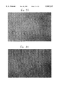
- FIG. 29 shows an example of furniture chatter marks according to a preferred embodiment of the invention.
- FIG. 30 shows an example of furniture chatter marks according to a preferred embodiment of the invention.
- FIG. 31 shows an example of furniture chatter marks according to a preferred embodiment of the invention.
- FIG. 32 shows an example of furniture chatter marks according to a preferred embodiment of the invention.
- FIG. 33 shows an example of furniture chatter marks according to a preferred embodiment of the invention.
- FIG. 34 shows an example of furniture chatter marks according to a preferred embodiment of the invention.
- FIG. 35 shows an example of furniture chatter marks according to a preferred embodiment of the invention.
- FIG. 36 shows an example of furniture chatter marks according to a preferred embodiment of the invention.
- FIG. 37 shows an example of furniture chatter marks according to a preferred embodiment of the invention.
- FIG. 38 shows an example of furniture chatter marks according to a preferred embodiment of the invention.
- FIG. 39 shows an example of furniture chatter marks according to a preferred embodiment of the invention.
- FIG. 40 shows an example of furniture chatter marks according to a preferred embodiment of the invention.
- FIG. 41 shows an example of furniture chatter marks according to a preferred embodiment of the invention.
- the programmable furniture texturing robotic system of the present invention is designated generally by the reference numeral 50 in FIG. 1.
- the programmable furniture texturing robotic system 50 includes a furniture texturing robot 51 which includes a programmable multiaxis robot 52 having a tool arm 54.
- the tool arm 54 has a tool end 56.
- a suitable programmable multiaxis robot is a MOTOMAN K120 six-axis robot commercially available from Sphearhead Automated Systems Inc. having a YASNAC MRC controller and a robot tolerance of ⁇ 0.1 mm.
- the MOTOMAN robot comes with dual 32 bit RISC processors that allow for smooth path motion, speed, accuracy and a 120 kg payload capacity.
- the MOTOMAN robot comes equipped with a teaching, editing and programming pendant with one touch programming execution. However, other robots may be selected without departing from the scope or spirit of the invention.
- the programmable multiaxis robot 52 is attached to a support frame 58.
- a table 60 is attached to the support frame 58 such that the programmable multiaxis robot 52, support frame 58, and table 60 form an integrated unit to maintain proper alignment of the tool end 56 of the arm 54 of the programmable multiaxis robot 52.
- the table 60 is a vacuum table which holds the furniture part in position while the programmable multiaxis robot produces texture markings on the furniture part. Vacuum tables for holding both flat and curved furniture parts in place are known in the art of furniture manufacturing for uses other than a programmable furniture texturing robotic system.
- the programmable furniture texturing robotic system 50 has a furniture texturing tool unit 62 fixedly attached to the tool end 56 of the tool arm 54.
- the furniture texturing tool unit 62 is fixedly attached to an attachment plate 64 at the tool end 56 of the tool arm 54.
- the attachment plate 64 is rotatable about an axis 65 substantially perpendicular to the attachment plate 64.
- the attachment plate 64 can be rotated by substantially 360° about the axis 65.
- the programmable multiaxis robot has a counter weight 66 attached at a distance from the tool end 56 of the tool arm 54 to substantially cancel a primary component of torque on the tool arm 54 generated by the furniture texturing tool unit 62.
- a robot other than a MOTOMAN K120 six-axis robot may require a counterweight and mounting configuration different from that of the preferred embodiment.
- FIG. 2A A top view of the programmable furniture texturing robotic system for a preferred embodiment is illustrated in FIG. 2A.
- This preferred embodiment has two tables 60, and a work cell 68.
- the work cell 68 preferably has a frame 69 made from 8 in ⁇ 6 in rectangular steel tubing.
- the work cell 68 is 25 ft 2 in ⁇ 17 ft 3 in.
- the work cell 68 is further enclosed by safety glass such as LEXAN guarding 70, which can best be seen illustrated in FIG. 2B.
- a YASNAC controller 72 and vacuum pump 74 are disposed proximate to the work cell 68.
- An air supply of 80 psi dried is suitable in this example.
- the preferred embodiment of this invention has two furniture texturing tool units 62 (FIG. 1).
- the user selects one of the two furniture texturing tool units 62 and attaches it to the attachment plate 64 of the programmable multiaxis robot 52.
- the specific furniture texturing tool unit 62 illustrated in FIG. 1 is an embodiment of a furniture distressing tool unit which is different from the preferred embodiment.
- Other alternative embodiments are within the scope and spirit of the invention, e.g., a furniture texturing tool unit 62 may include both furniture distressing and furniture chattering tools.
- FIG. 3 shows a preferred embodiment of the furniture distressing tool unit 76.
- the furniture distressing tool unit 76 has a multitool turret 78 which has a tool end attachment region 80.
- the tool end attachment region 80 has a multitool attachment plate 82 attached at one face to the multitool turret 78 and at an opposing face to the attachment plate 64.
- a suitable material for the multitool attachment plate 82 and the multitool turret 78 is aluminum.
- the multitool turret 78 has a plurality of furniture distressing tool attachment regions, such as 84, 86, and 88. A greater or lesser number of furniture distressing tool attachment regions may be selected without departing from the spirit or scope of the invention. Tools other than furniture distressing tools, such as furniture chattering tools, may be attached at the furniture distressing attachment regions.
- the furniture distressing tool unit 76 includes a plurality of furniture distressing tools attached to the multitool turret 78.
- a suitable material for the multitool turret is aluminum.
- a first furniture distressing tool is a router distressing tool 90.
- the distressing router 90 has a router bit 92 which is selectable according to the desired texturing effect.
- the distressing router 90 has an end plate 94 and a router mounting packet 96 to attach router 98 to the multitool turret 78.
- a suitable router 98 is available from Porter Cable (Model 6902).
- the router bracket 96 is preferably constructed from aluminum such that it defines a circular hole therethrough for accommodating the router 98, as one may view more clearly in FIG. 4A.
- a saw cut gap 100 and mechanical fastener 102 permit the bracket to be clamped tightly around a selected circumferential region of the router 98.
- a bracket 104 may be used instead of bracket 96 (see FIG. 4B).
- the furniture distressing tool unit 76 (FIG. 3) includes a compound distressing tool unit 106 which has a plurality of furniture distressing tools.
- the compound furniture distressing tool unit 106 has a compound furniture distressing tool attachment bracket 108 which preferably attaches to a furniture distressing tool attachment region 86 by mechanical fasteners.
- a plurality of furniture distressing tools are attached to the compound furniture distressing tool attachment bracket 108 (see FIG. 3).
- a descalar distressing tool 110, a rock distressing tool 112 and a hatchet distressing tool 114 are attached to the compound furniture distressing tool attachment bracket 108.
- the hatchet distressing tool 114 is immediately behind the rock distressing tool 112 in FIG. 3.
- the hatchet distressing tool 114 and rock distressing tool 112 are more clearly visible from a side view illustrated in FIG. 6.
- the hatchet distressing tool 114 has an expansion component 116 attached to compound furniture distressing tool attachment bracket 108 by hatchet attachment bracket 118 mechanically fastened to the compound furniture distressing tool attachment brackets 108.
- the expansion component is an air cylinder selected from conventionally known air cylinders and is attached to a variable pressure air supply unit in a conventional manner (not shown).
- a suitable commercially available air cylinder is a NUMATICS ACTUATOR S2FM-02A1D-CAA2.
- a slidable member 120 such as a piston is attached to a hatchet holder 122.
- the hatchet holder 122 is attached to the distressing hatchet 124'.
- a suitable material for the distressing hatchets 124 and 124' is tool steel.
- a first angle 123 of approximately 90° and a second angle 125 of approximately 20° was found to be suitable for the distressing hatchet 124' .
- the operating elements of the rock distressing tool 112 are similar in construction to the hatchet distressing tool 114 (FIG. 6).
- the rock distressing tool has an expansion component 127 which is preferably, for example, one or more conventional pneumatic air cylinders.
- the expansion component 127 is attached to a variable pressure air source (not shown).
- the expansion component 127 is preferably attached to the compound furniture distressing tool attachment bracket 108 by the air cylinder brackets 126 with mechanical fasteners.
- the rock distressing tool has a slidable member 128 which is part of a conventional air cylinder.
- the distressing rock element 130 is itself attached to a rock spacer 132, which in turn is attached to the slidable member 128.
- the distressing rock element 130 includes a distressing face 134, perhaps best seen in FIGS. 3, 6 and 10B, that has a plurality of rock-like shapes including convex and concave surface regions as well as sharp and rounded areas to replicate actual rock-like effects on the article of furniture.
- the plurality of rock-like shapes are selectable in accordance with the desired furniture distressing effect.
- the rock spacer 132 is also illustrated in FIGS. 9A and 9B.
- a suitable material for the rock spacer 132 is aluminum.
- FIGS. 10A and 10B show an enlarged view of the distressing rock element 130.
- a suitable material for the distressing rock element 130 is steel.
- the descalar distressing tool 110 has a descalar bracket 136 attached to the compound furniture distressing tool attachment bracket 108, preferably by mechanical fasteners.
- the descalar distressing tool 110 includes a descalar 138, similar to a conventional descalar, but modified such that it has two descalar pins 140 rather than a large number of descalar pins as in a conventional descalar used in the metal industry for removing burs from metal parts.
- the modified descalar pins 140 are sharpened.
- the descalar pins 140 are typically attached at an attachment end 142 of the descalar 138. Descalars are also known as jet chisels.
- a suitable commercially available descalar is the jet chissel by Nittokohkico Ltd. (Model JT-20).
- the descalar 138 has conventional pistons which move the descalar pins 140 in a back-and-forth motion along the longitudinal direction of the descalar 138.
- the motion of the descalar pins 140 typically have an amplitude of about, for example, 0.2 to 0.5 inches but greater or lesser movement is contemplated.
- the attachment end 142 of the descalar 138 is typically circular as viewed end-on and the descalar pins 140 are typically attached off center.
- the attachment end 142 typically rotates about a center axis of the circular attachment end 142 in operation so that pins 140 can move inwardly, outwardly, and/or rotate or incorporate a plurality of these motions, as well as a variety of angular positions relative to the furniture surface.
- FIG. 11 illustrates a more detailed view of the descalar bracket 136.
- the descalar bracket 136 has a tube 144 which is preferably aluminum. Brackets 146 and 148 are preferably attached to aluminum tube 144 by mechanical fasteners. Bracket 150 is preferably attached to aluminum tube 144 by welding. An angle 151 of approximately 30° is suitable for the bracket 150. Aluminum is a suitable material for brackets 146, 148 and 150.
- the bracket 150 attaches to the compound furniture distressing tool attachment bracket 108, preferably by mechanical fasteners (FIG. 3). As one can see illustrated in FIG. 3, the descalar distressing tool 110 also has a descalar spacer 152.
- the furniture distressing tool unit 76 has four furniture distressing tools, the furniture distressing tool unit 76 is not limited to that exact number. A greater or lesser number of distressing tools is within the scope and spirit of the invention.
- the second furniture texturing tool unit of the preferred embodiment is a furniture chattering tool unit 154 illustrated in FIGS. 12 and 13.
- the furniture chattering tool unit 154 has a support frame 156 with an attachment region 158 to attach and detach the furniture chattering tool unit 154 to the attachment plate 64 of the programmable multiaxis robot 52 (see FIG. 1 for an illustration of the attachment plate 64).
- the support frame 156 has an upper frame portion 160 and a lower frame portion 162.
- a pair of Gibb plates 164 are attached to lower frame portion 162 by mechanical fasteners and slidably attached to upper frame portion 160 by bearings 166. (See FIG. 12 for an illustration of the bearings 166 on one of the two Gibb plates 164.
- a motor 168 is disposed within the support frame and in contact with a bottom surface 170 of the lower support frame 162.
- the motor 168 is preferably an air operated motor and is selectable from conventional motors.
- a model 8AM-NRV-76 6ZC-94 commercially available from Gaft Manufacturing Corp. is suitable.
- the motor 168 has a drive shaft 172 which extends in a direction from the attachment end 158 of the support frame 156 to a furniture part end 174 of the furniture chattering tool unit 154.
- a plurality of compression springs 176 are disposed between a top surface 178 of the motor 168 and an inner surface 180 of the upper frame portion 160 such that the compression springs 176 exert a force tending to increase the distance between the motor 168 and the inner surface 180 of the upper frame portion 160 when the compression springs 176 are in a compressed state.
- a gas shock 182 is attached at one lateral side of the support frame 156 such that one end is attached to the upper frame portion 160 and the other end is attached to the lower frame portion 162.
- another gas shock 184 is attached at the opposite lateral side of the support frame 156 such that one end is attached to the upper frame portion 160 and the other end is attached to the lower frame portion 162.
- the upper frame portion 160 has a cross support member 186.
- the lower support frame portion 162 has a cross support member 188.
- a suitable material for the cross support members 186 and 188 is steel.
- a support member 190 is slidably attached between the cross support member 186 of the upper frame portion 160 to the cross support member 188 of the lower frame portion 162.
- An expansion spring 192 has one end attached to the cross support member 186 of the upper frame portion 160 and the other end attached to the cross support member 188 of the lower frame portion 162.
- the furniture chattering tool unit 154 has a saw blade 194 attached substantially perpendicularly to the drive shaft 172 and substantially at its center point.
- the furniture chattering tool unit 154 also has an adjustable roller bearing unit 196 fixed to the a bottom surface 198 of the support frame 156.
- the roller bearing unit 196 extends substantially parallel to the drive shaft 172 of the motor 168 and has a roller bearing 200 at a furniture part end 174 of the furniture chattering tool unit 154.
- a plate 202 is fixedly attached between the saw blade 194 and the drive shaft 172 such that it is substantially parallel to the saw blade 194.
- a furniture distressing tool unit 76 or a furniture chattering tool unit 154 and attaches it to the attachment plate 64 of the tool end 56 of the tool arm 54 of the programmable multiaxis robot 52.
- the preferred embodiment has two different furniture texturing tool units 62, a lesser number or a greater number of tool units 62 are within the scope and spirit of the invention.
- an alternative embodiment may include both furniture distressing and chattering tools on the same furniture texturing tool unit.
- the table 60 is a vacuum table adapted from vacuum tables known in the art for furniture manufacturing.
- a pod 206 is placed on the vacuum table and the flat part is placed on the pod 206.
- a mold (not shown) is placed on top of the vacuum table. The mold may define openings to provide a surface with a pressure lower than atmospheric pressure such that the curved or irregular furniture part is held to the surface due to the vacuum. Alternatively, or in combination thereof, the curved or irregular furniture part may be clamped or otherwise fastened to the mold.
- the user programs the programmable furniture texturing robot 51 to perform a predetermined sequence of furniture texturing operations.
- the MOTOMAN K120 robot is suitable since it has a teach mode and a teaching input device in which the user uses the teaching input device to program all of the robot's motions.
- the user positions the desired furniture texturing tool at a desired point in contact with, or proximate to, the surface point of the furniture part 204.
- the configuration of the furniture texturing robot 51 is recorded as a step in the program.
- the user selects another point of the surface of the furniture part 204 such that the desired furniture texturing tool is in contact with, or approximate to, the selected point.
- the MOTOMAN K120 robot also permits linear and circular interpolation between selected points. The user repeats this process such that the desired furniture texturing marks are produced at the desired locations on the surface of the furniture part.
- the program is ready to be used in production runs to produce the selected furniture texturing marks on a plurality of furniture parts.
- a furniture part is secured to a table 60. It is suitable to secure the furniture part in the production run in the same way as described above for securing a wood part, or a furniture part, to a table 60 for programming the furniture texturing robot 51.
- the programmable multiaxis robot 52 of the preferred embodiment is then run through the predetermined sequence of furniture texturing operations which the user programmed during the programming step.
- the furniture texturing robot 51 will thereby substantially produce the predetermined furniture texturing marks on the surface of the furniture part.
- the user After the furniture texturing robot 51 has completed the predetermined sequence of furniture texturing operations, the user removes the furniture part 204 from the table 60. The user then disposes another furniture part 204 on the table 60 in substantially the same manner as described above.
- the programmable multiaxis robot 52 is then run through the predetermined sequence of furniture texturing operations, thus producing a second furniture part with substantially the same furniture texturing marks as in the first mentioned furniture part. This process is then repeated to produce a desired number of furniture parts with substantially the same texture marks.
- the programmable furniture texturing robotic system 50 is not limited to a single table 60.
- the programmable furniture texturing robotic system 50 has two substantially identical tables 60. This permits a user, either manually or with a suitable apparatus, to remove the textured furniture part and to replace it with an untextured part while the furniture texturing robot 51 runs through the predetermined sequence of furniture texturing operations on a furniture part on the other table 60.
- the user selects a furniture distressing tool unit.
- the furniture distressing tool unit 76 is selected to produce furniture distress marks.
- Each of the plurality of furniture distressing tools of the furniture distressing tool unit 76 produce a plurality of furniture distress marks.
- FIG. 3 illustrates a furniture distressing router 90 proximate to a flat furniture part 204.
- the flat furniture part 204 is disposed on a pod plate 206 which, in turn, is disposed on the top surface of the table 60.
- the table 60 is a vacuum table with a top aluminum vacuum plate 208.
- FIG. 14 illustrates a router bit 92 in contact with the furniture part 204 such that a longitudinal axis 210 of the distressing router 90 forms an angle 212 with the surface of the furniture part 204.
- an angle 212 of approximately 30° is suitable.
- An angle 213 of approximate 75° is suitable for the cutting edge.
- the user selects a second point on the surface of the furniture part 204 with a depth of penetration of the bit 92 into the surface of the wood part 204 similar to or the same as that depicted in FIG. 14 and selects a linear interpolation between the two points to produce a substantially straight line such as that shown as a horizontal dark line in FIG. 15.
- uneven vein lines, or cut lines can be produced in a similar manner by selecting different penetration depths of the bit 92 into the surface of the furniture part 204 at the different selected points, or selecting nonlinear interpolation between the points, selecting a plurality of points with nonuniform depths of penetration of the bit 92 into the furniture part 204 or which are not precisely along a single line, or some combination of these or other factors.
- FIG. 16 shows an example of an uneven cut line across the center of the figure. This type of distress mark simulates markings which would be produced in hand-crafted furniture.
- FIGS. 17 and 18 show additional examples of uneven cut or vein lines.
- the depth of the cut lines is selectable for the router bit 92, and other router bits may be selected. A typical depth of such a cut may be between 1 and 4 mm.
- FIG. 19 illustrates an example in which the router bit 92 is brought into contact with the furniture part 204 at a different angle 214 compared to the first mentioned angle 212.
- an angle 214 of approximately 60° is suitable.
- the user may program the robot to come into contact with the furniture part 204 as illustrated in FIG. 19 in order to simulate cigarette burn marks.
- the router produces an indentation in the surface of the furniture part 204 which is approximately 3-7 cm long such that the center of the indentation is deeper than the edges.
- Such a simulated cigarette burn mark is illustrated in the upper left hand corner of FIG. 20.
- the distressing router 90 refers to producing simulated uneven vein lines, uneven plank cut lines or cigarette burn marks, it is not limited to producing only those types of distress marks.
- the distressing hatchet 114 is used to produce a plurality of furniture distress marks.
- the furniture texturing robot 51 is positioned such that the hatchet is above, or proximate to, a point on the furniture part 204.
- the distance of the hatchet above the furniture part 204 is selected such that an impulse from the expansion component 116 forces the piston 120 (FIG. 6) and the hatchet blade 124 into the surface of the furniture part 204 to the desired depth.
- the user can select the desired angle between the distressing hatchet 124 and the furniture part 204.
- Typical simulated hatchet distress marks in which the distressing hatchet 124 impacts the surface of the furniture part 204 at nearly orthogonal angles are shown in FIGS. 17, 21 and 22.
- the user may also program the furniture texturing robot 51 such that the distressing hatchet 114 produces simulated wood split marks.
- the expansion component 116 does not provide an impulse to the distressing hatchet 124.
- the blade of the distressing hatchet 124 is brought into contact with the surface of the furniture part 204.
- a corner of the hatchet blade is brought into contact with the surface of the furniture part 204.
- the user programs the robot such that the hatchet is drawn across the surface of the furniture part 204 substantially in a straight line motion which is substantially parallel to the surface of the furniture part 204. Examples of such distress marks are the two shorter distress lines shown in FIG. 18.
- the specification describes the use of the hatchet distressing tool 114 to simulate hatchet marks or wood split marks, the invention is not limited to producing only those types of simulated furniture distress marks with the hatchet distressing tool 114.
- the user can program the rock distressing tool 112 to produce a plurality of the furniture distress marks.
- the surface 134 of the distressing rock 130 has a plurality of concave and convex regions. This results in portions which protrude relative to other portions of the surface. These protrusions are selectable in a great variety of forms since they can be used to simulate distress marks produced by rocks, and actual rocks have a great variety of surface features.
- the user positions the furniture texturing robot 51 such that a desired portion of the distressing rock 130 surface 134 is proximate to, and above, a region of the furniture part 204 in which the user desires to produce a simulated rock distress mark.
- the furniture texturing robot 51 is programmed such that the expansion component 127 delivers an impulse to the rock 130 by means of the piston 128 and rock spacer 132, so as to thrust the surface 134 of the distressing rock 130 into the surface of the furniture part 204.
- the height of the rock distressing tool 112 is selected so as to produce a desired depth of penetration of the rock surface 134 into the surface of the furniture part 204. Typical penetration depths are 1-4 mm.
- the user can further select various angles of orientation of the rock distressing tool 112 relative to the surface of the furniture part 204 to produce different rock distress marks. Consequently, a single distressing rock 130 with a plurality of concave and convex surface regions 134 can produce a plurality of simulated rock distress marks.
- FIG. 21 shows an example of a rock distress mark.
- the center of FIG. 22 shows another example of a rock distress mark.
- the specification describes programming the furniture texturing robot 51 such that it produces a plurality of simulated rock distress marks with the rock distressing tool 112, the invention is not limited to only simulating rock distress marks with the rock distressing tool 112.
- the user can program the furniture texturing robot 51 to produce a plurality of furniture distress marks with the descalar distressing tool 110 (see FIG. 3).
- the user positions the furniture texturing robot 51 such that the descalar pins 140 are oriented such that their longitudinal axis is substantially orthogonal to a surface region of the furniture part 204.
- the user programs the furniture texturing robot 51 such that the descalar pins 140 are thrust into the surface of the furniture part 204 by the descalar piston.
- the user programs the furniture texturing robot 51 such that the descalar pins 140 move quickly into proximity with the surface of the furniture part 204 and then out of proximity of the furniture part 204.
- This process is repeated at predetermined rarefied locations, so as to simulate a random pattern of rarefied and approximately circular wormhole distress marks.
- This sequence results in the descalar appearing to hop randomly about the surface of the furniture part 204.
- FIG. 16 shows an example of such wormhole furniture distress marks in the upper right hand corner.
- FIG. 23 shows another example of wormhole distress marks along with other types of distress marks.
- a typical wormhole distress mark is approximately a millimeter deep and approximately circular in shape.
- the user may also program the robot such that the descalar pins 140 come into contact with the surface of the furniture part 204 at angles less than 90° so as to produce oblong or elliptical shaped wormhole marks.
- the user may also program the furniture texturing robot 51 to produce simulated wood rot marks with the descalar distressing tool 110.
- the user programs the furniture texturing robot 51 such that the descalar pins 144 come into contact with the furniture part 204 in a highly concentrated region and typically at very shallow angles of the longitudinal axis of the descalar pins relative to the surface of the furniture part 204.
- the upper edge of FIG. 24 illustrates the simulated wood rot furniture distress marks.
- FIG. 24 includes other types of distress marks such as a random pattern of wormhole marks and an uneven cut mark across the bottom.
- FIGS. 21, 25 and 26 provide further examples of simulated wood rot distress marks produced according to this invention.
- the specification describes simulating wormhole distress marks and wood rot distress marks using the descalar distressing tool 110, it is not limited to producing only these types of distress marks with the descalar distressing tool.
- the user selects the furniture chattering tool unit 154, illustrated in FIGS. 12 and 13, and attaches it to the attachment plate 64 of the programmable multiaxis robot 52, if the user desires to program the furniture texturing robot 51 to produce chattering texture marks according to the preferred embodiment.
- the user adjusts the roller bearing unit 196 such that the roller bearing 200 comes into contact with the surface of the furniture part 204 after the saw blade 194 has penetrated the surface of the furniture part 204 to a desired depth.
- the user programs the robot such that the saw blade 194 has a desired angle of incidence with the surface of the furniture part 204. Selecting different angles of incidence or depths of cutting, provide different chattering effects.
- the user programs the robot to drag the furniture chattering tool unit 154 across a predetermined region of the surface of the furniture part 204.
- the user may select to program the furniture texturing robot 51 to produce a substantially uniform chattering pattern across the surface of the furniture part 204, or may vary the chattering path, saw blade angle and depth of cutting at different regions of the surface of the furniture part 204.
- the maximum depth of a chatter mark relative to the adjacent minimum depth is typically one to a few millimeters.
- the user may program the furniture texturing robot 51 to produce predetermined furniture chattering marks which appear to be random and others which cannot reasonably be produced by known methods.
- FIGS. 27-41 show a variety of furniture chattering marks which one may produce with the furniture texturing robotic system of this invention. However, this invention is not limited to producing only the predetermined chattering marks shown in the examples of FIGS. 27-41.
- the programmable furniture texturing robotic system of this invention is not limited to only the specific robot described, the specific furniture texturing units described in detail, and the specific table.
- the invention is not limited to the two furniture texturing tool units described in detail nor to the specific tools, methods of texturing furniture, nor only the specific examples of textured furniture of the preferred embodiments.
Abstract
Description
Claims (19)
Priority Applications (2)
| Application Number | Priority Date | Filing Date | Title |
|---|---|---|---|
| US08/890,792 US5987217A (en) | 1997-07-11 | 1997-07-11 | Robotic furniture texturing |
| US09/134,899 US6330492B1 (en) | 1997-07-11 | 1998-08-17 | Robotic furniture texturing |
Applications Claiming Priority (1)
| Application Number | Priority Date | Filing Date | Title |
|---|---|---|---|
| US08/890,792 US5987217A (en) | 1997-07-11 | 1997-07-11 | Robotic furniture texturing |
Related Child Applications (1)
| Application Number | Title | Priority Date | Filing Date |
|---|---|---|---|
| US09/134,899 Division US6330492B1 (en) | 1997-07-11 | 1998-08-17 | Robotic furniture texturing |
Publications (1)
| Publication Number | Publication Date |
|---|---|
| US5987217A true US5987217A (en) | 1999-11-16 |
Family
ID=25397149
Family Applications (2)
| Application Number | Title | Priority Date | Filing Date |
|---|---|---|---|
| US08/890,792 Expired - Fee Related US5987217A (en) | 1997-07-11 | 1997-07-11 | Robotic furniture texturing |
| US09/134,899 Expired - Fee Related US6330492B1 (en) | 1997-07-11 | 1998-08-17 | Robotic furniture texturing |
Family Applications After (1)
| Application Number | Title | Priority Date | Filing Date |
|---|---|---|---|
| US09/134,899 Expired - Fee Related US6330492B1 (en) | 1997-07-11 | 1998-08-17 | Robotic furniture texturing |
Country Status (1)
| Country | Link |
|---|---|
| US (2) | US5987217A (en) |
Cited By (14)
| Publication number | Priority date | Publication date | Assignee | Title |
|---|---|---|---|---|
| US6609546B1 (en) | 2001-07-27 | 2003-08-26 | Thomasville Furniture Industries, Inc. | Furniture with distressed appearance |
| US6660333B2 (en) * | 2001-01-29 | 2003-12-09 | David Frame | Apparatus and methods for producing artificially distressed plank flooring |
| EP2062707A2 (en) * | 2007-11-23 | 2009-05-27 | Kajanor Oy | Method for treating wooden surfaces, use of said method and wooden surface obtained by the method |
| US20090223600A1 (en) * | 2008-03-10 | 2009-09-10 | Tappan John C | Automated floor board texturing cell and method |
| US20090277537A1 (en) * | 2008-05-09 | 2009-11-12 | Shaw Industries Group Inc. | Hardwood texturing apparatus and methods for using same |
| US20120142255A1 (en) * | 2010-12-07 | 2012-06-07 | The Boeing Company | Robotic surface preparation by a random orbital device |
| ITMI20110575A1 (en) * | 2011-04-08 | 2012-10-09 | T & D Robotics S R L | ROBOT AND METHOD FOR THE PROCESSING OF FURNISHINGS AND FURNISHINGS AND ARCHITECTURAL COMPLEMENTS |
| US20130109277A1 (en) * | 2011-11-02 | 2013-05-02 | The Boeing Company | Robotic end effector including multiple abrasion tools |
| US20140342125A1 (en) * | 2013-03-15 | 2014-11-20 | Shaw Industries Group, Inc. | Automated hardwood texturing system and associated methods |
| US20150360386A1 (en) * | 2012-04-10 | 2015-12-17 | Armstrong World Industries, Inc. | Material surface distressing blade |
| CN111830047A (en) * | 2020-07-16 | 2020-10-27 | 云南中烟工业有限责任公司 | Cigarette fly ash detection device and detection method based on machine vision |
| CN111958737A (en) * | 2020-07-22 | 2020-11-20 | 盐城鼎恒机械有限公司 | Make things convenient for angle regulation's DH series blunt sword all-in-one of hand pull line |
| US11305445B1 (en) * | 2020-04-24 | 2022-04-19 | John Peachey | Surface texturing apparatus |
| US20220126455A1 (en) * | 2019-02-08 | 2022-04-28 | Miralis Inc. | Robotic systems and methods for assembling furniture |
Families Citing this family (10)
| Publication number | Priority date | Publication date | Assignee | Title |
|---|---|---|---|---|
| US6434449B1 (en) * | 2000-08-03 | 2002-08-13 | Pierre De Smet | Method and device for automated robot-cell calibration |
| US20050218575A1 (en) * | 2003-11-24 | 2005-10-06 | Larry Cook | Vacuum workholding fixture |
| US20070283780A1 (en) * | 2006-05-02 | 2007-12-13 | Ed Smock | Automated Device and Method for Manufacturing a Door |
| US7966713B2 (en) * | 2006-05-17 | 2011-06-28 | The Boeing Company | Tooling head mounted structural positioning |
| US9026242B2 (en) * | 2011-05-19 | 2015-05-05 | Taktia Llc | Automatically guided tools |
| JP6301314B2 (en) | 2012-04-26 | 2018-03-28 | シェイパー ツールズ, インク.Shaper Tools, Inc. | System and method for performing work on a material or locating a device relative to the surface of a material |
| US9114537B2 (en) * | 2013-10-31 | 2015-08-25 | Apex Brands, Inc. | Tooling system with electronic signal maintenance |
| EP3657279B1 (en) | 2015-05-13 | 2023-03-29 | Shaper Tools, Inc. | Systems, methods and apparatus for guided tools |
| CA3033683A1 (en) | 2016-08-19 | 2018-02-22 | Shaper Tools, Inc. | Systems, methods and apparatus for sharing tool fabrication and design data |
| CN111958733B (en) * | 2020-07-21 | 2022-02-11 | 盐城鼎恒机械有限公司 | DH series hand-pulled pattern blunt knife all-in-one machine facilitating lubrication of transmission mechanism |
Citations (6)
| Publication number | Priority date | Publication date | Assignee | Title |
|---|---|---|---|---|
| US3756295A (en) * | 1972-06-05 | 1973-09-04 | Timbercraft Inc | Device for simulating a hand hewn surface |
| US4116248A (en) * | 1977-09-23 | 1978-09-26 | Koppers Company, Inc. | Apparatus for texturizing a material |
| US4207936A (en) * | 1978-11-01 | 1980-06-17 | Arbour Raymond L | Textured wood surfacing |
| US4338052A (en) * | 1980-03-31 | 1982-07-06 | Northrop Corporation | Variable geometry router |
| US4372357A (en) * | 1979-01-05 | 1983-02-08 | Globe Machine Manufacturing Company | Machine for profiling wood panel to simulate lap siding |
| US5493767A (en) * | 1994-12-15 | 1996-02-27 | Thermwood Corporation | System and method for positioning workpieces on CNC machines |
Family Cites Families (1)
| Publication number | Priority date | Publication date | Assignee | Title |
|---|---|---|---|---|
| DE19654292A1 (en) * | 1996-12-27 | 1998-07-02 | Ibg Automation Gmbh | Device and method for manufacturing pieces of furniture |
-
1997
- 1997-07-11 US US08/890,792 patent/US5987217A/en not_active Expired - Fee Related
-
1998
- 1998-08-17 US US09/134,899 patent/US6330492B1/en not_active Expired - Fee Related
Patent Citations (6)
| Publication number | Priority date | Publication date | Assignee | Title |
|---|---|---|---|---|
| US3756295A (en) * | 1972-06-05 | 1973-09-04 | Timbercraft Inc | Device for simulating a hand hewn surface |
| US4116248A (en) * | 1977-09-23 | 1978-09-26 | Koppers Company, Inc. | Apparatus for texturizing a material |
| US4207936A (en) * | 1978-11-01 | 1980-06-17 | Arbour Raymond L | Textured wood surfacing |
| US4372357A (en) * | 1979-01-05 | 1983-02-08 | Globe Machine Manufacturing Company | Machine for profiling wood panel to simulate lap siding |
| US4338052A (en) * | 1980-03-31 | 1982-07-06 | Northrop Corporation | Variable geometry router |
| US5493767A (en) * | 1994-12-15 | 1996-02-27 | Thermwood Corporation | System and method for positioning workpieces on CNC machines |
Cited By (23)
| Publication number | Priority date | Publication date | Assignee | Title |
|---|---|---|---|---|
| US6660333B2 (en) * | 2001-01-29 | 2003-12-09 | David Frame | Apparatus and methods for producing artificially distressed plank flooring |
| US6609546B1 (en) | 2001-07-27 | 2003-08-26 | Thomasville Furniture Industries, Inc. | Furniture with distressed appearance |
| EP2062707A2 (en) * | 2007-11-23 | 2009-05-27 | Kajanor Oy | Method for treating wooden surfaces, use of said method and wooden surface obtained by the method |
| EP2062707A3 (en) * | 2007-11-23 | 2013-08-28 | Kajanor Oy | Method for treating wooden surfaces, use of said method and wooden surface obtained by the method |
| US20090223600A1 (en) * | 2008-03-10 | 2009-09-10 | Tappan John C | Automated floor board texturing cell and method |
| US8186399B2 (en) | 2008-03-10 | 2012-05-29 | Unilin Flooring Nc Llc | Automated floor board texturing cell and method |
| US20090277537A1 (en) * | 2008-05-09 | 2009-11-12 | Shaw Industries Group Inc. | Hardwood texturing apparatus and methods for using same |
| US8186397B2 (en) | 2008-05-09 | 2012-05-29 | Columbia Insurance Company | Hardwood texturing apparatus and methods for using same |
| US9352482B2 (en) | 2008-05-09 | 2016-05-31 | Columbia Insurance Company | Hardwood texturing apparatus and methods for using same |
| US8517799B2 (en) * | 2010-12-07 | 2013-08-27 | The Boeing Company | Robotic surface preparation by a random orbital device |
| US20120142255A1 (en) * | 2010-12-07 | 2012-06-07 | The Boeing Company | Robotic surface preparation by a random orbital device |
| ITMI20110575A1 (en) * | 2011-04-08 | 2012-10-09 | T & D Robotics S R L | ROBOT AND METHOD FOR THE PROCESSING OF FURNISHINGS AND FURNISHINGS AND ARCHITECTURAL COMPLEMENTS |
| US10035237B2 (en) * | 2011-11-02 | 2018-07-31 | The Boeing Company | Robotic end effector including multiple abrasion tools |
| US20130109277A1 (en) * | 2011-11-02 | 2013-05-02 | The Boeing Company | Robotic end effector including multiple abrasion tools |
| US20150360386A1 (en) * | 2012-04-10 | 2015-12-17 | Armstrong World Industries, Inc. | Material surface distressing blade |
| US10071456B2 (en) * | 2013-03-15 | 2018-09-11 | Columbia Insurance Company | Automated hardwood texturing system and associated methods |
| US20140342125A1 (en) * | 2013-03-15 | 2014-11-20 | Shaw Industries Group, Inc. | Automated hardwood texturing system and associated methods |
| US20220126455A1 (en) * | 2019-02-08 | 2022-04-28 | Miralis Inc. | Robotic systems and methods for assembling furniture |
| US11305445B1 (en) * | 2020-04-24 | 2022-04-19 | John Peachey | Surface texturing apparatus |
| CN111830047A (en) * | 2020-07-16 | 2020-10-27 | 云南中烟工业有限责任公司 | Cigarette fly ash detection device and detection method based on machine vision |
| CN111830047B (en) * | 2020-07-16 | 2022-07-01 | 云南中烟工业有限责任公司 | Cigarette fly ash detection device and detection method based on machine vision |
| CN111958737A (en) * | 2020-07-22 | 2020-11-20 | 盐城鼎恒机械有限公司 | Make things convenient for angle regulation's DH series blunt sword all-in-one of hand pull line |
| CN111958737B (en) * | 2020-07-22 | 2022-06-17 | 盐城鼎恒机械有限公司 | Make things convenient for angle regulation's DH series blunt sword all-in-one of hand pull line |
Also Published As
| Publication number | Publication date |
|---|---|
| US6330492B1 (en) | 2001-12-11 |
Similar Documents
| Publication | Publication Date | Title |
|---|---|---|
| US5987217A (en) | Robotic furniture texturing | |
| CN101175594A (en) | Digitally-controlled engraving machine | |
| JPS62221501A (en) | Saw-cutting drill | |
| ATE333671T1 (en) | METHOD FOR CONTROLLING THE WORKING MOVEMENT OF A TOOL FOR MATERIAL-REMOVAL PROCESSING OF A MATERIAL BLOCK | |
| WO2006075209A3 (en) | Laser machine tool having a x-y sliding structure with mass balancing means | |
| CN206199966U (en) | It is easy to the cutting corner of angle steel device of operation | |
| WO1994006605A1 (en) | Mat cutting system | |
| CA2594000C (en) | Woodworking machine for shaping molding | |
| US5547003A (en) | Device and method for forming square inside corners on raised panels formed of single workpieces | |
| US3978842A (en) | Masonry block cutter | |
| US20020179183A1 (en) | One pass combination of traditional and multi-axis material carving machine | |
| WO2008082322A1 (en) | Method for producing a shaped surface and a device for carrying out said method | |
| US8042435B2 (en) | Special articulating tool holder | |
| US6315017B1 (en) | Joint jig for use with either a table-mounted or a hand-held router | |
| FI127139B (en) | A method of making a wood structure having a decorative pattern, a patterning machine for patterning a piece of wood, and a decorative wood structure | |
| US5395026A (en) | Tile cutting pliers | |
| JP2008217275A (en) | Machining method and machining apparatus | |
| JP2013184227A (en) | Woodworking copying apparatus | |
| ATE11656T1 (en) | MACHINE FOR SIMULTANEOUSLY DOORING THE ENDS OF A BOARD. | |
| CA2098064A1 (en) | Elongated cutting tool for wood working and apparatus for and method of grinding the same | |
| CN212371945U (en) | Tool setting positioner | |
| JP2000198001A5 (en) | Cutting tools and free-form surface cutting methods and cutting equipment | |
| JP3045535U (en) | Processing equipment and cutting equipment | |
| WO1992003263A1 (en) | A tool | |
| JP3016349U (en) | Cutting jig to be attached to electric saw |
Legal Events
| Date | Code | Title | Description |
|---|---|---|---|
| AS | Assignment |
Owner name: CENTURY FURNITURE INDUSTRIES, INC., NORTH CAROLINA Free format text: ASSIGNMENT OF ASSIGNORS INTEREST;ASSIGNORS:WISNIEWSKI, JOSEPH;JONES, ROGER;REEL/FRAME:009088/0958 Effective date: 19971209 |
|
| AS | Assignment |
Owner name: BANK OF AMERICA, N.A., GEORGIA Free format text: NOTICE OF GRANT OF SECURITY INTEREST;ASSIGNOR:CENTURY FURNITURE INDUSTRIES, INC.;REEL/FRAME:011190/0019 Effective date: 20000927 |
|
| FPAY | Fee payment |
Year of fee payment: 4 |
|
| REMI | Maintenance fee reminder mailed | ||
| AS | Assignment |
Owner name: BANK OF AMERICA, N.A., AS AGENT, GEORGIA Free format text: SECURITY INTEREST;ASSIGNOR:CENTURY FURNITURE, LLC;REEL/FRAME:014499/0620 Effective date: 20000927 |
|
| FPAY | Fee payment |
Year of fee payment: 8 |
|
| AS | Assignment |
Owner name: BANK OF AMERICA, N.A., GEORGIA Free format text: NOTICE OF GRANT OF SECURITY INTEREST IN PATENTS;ASSIGNOR:CENTURY FURNITURE, LLC;REEL/FRAME:021029/0504 Effective date: 20080528 |
|
| REMI | Maintenance fee reminder mailed | ||
| LAPS | Lapse for failure to pay maintenance fees | ||
| STCH | Information on status: patent discontinuation |
Free format text: PATENT EXPIRED DUE TO NONPAYMENT OF MAINTENANCE FEES UNDER 37 CFR 1.362 |
|
| FP | Lapsed due to failure to pay maintenance fee |
Effective date: 20111116 |
|
| AS | Assignment |
Owner name: BANK OF AMERICA, N.A., GEORGIA Free format text: NOTICE OF GRANT OF SECURITY INTEREST IN PATENTS;ASSIGNOR:CENTURY FURNITURE, LLC;REEL/FRAME:030663/0204 Effective date: 20130528 Owner name: CENTURY FURNITURE, LLC, NORTH CAROLINA Free format text: TERMINATION AND RELEASE OF SECURITY INTEREST IN PATENTS;ASSIGNOR:BANK OF AMERICA, N.A., AS AGENT;REEL/FRAME:030662/0987 Effective date: 20130528 Owner name: CENTURY FURNITURE, LLC, NORTH CAROLINA Free format text: TERMINATION AND RELEASE OF SECURITY INTEREST IN PATENTS;ASSIGNOR:BANK OF AMERICA, N.A.;REEL/FRAME:030662/0982 Effective date: 20130528 |