US5980335A - Electrical terminal - Google Patents
Electrical terminal Download PDFInfo
- Publication number
- US5980335A US5980335A US09/049,489 US4948998A US5980335A US 5980335 A US5980335 A US 5980335A US 4948998 A US4948998 A US 4948998A US 5980335 A US5980335 A US 5980335A
- Authority
- US
- United States
- Prior art keywords
- fabricated
- electrical terminal
- piece electrical
- metal
- strip
- Prior art date
- Legal status (The legal status is an assumption and is not a legal conclusion. Google has not performed a legal analysis and makes no representation as to the accuracy of the status listed.)
- Expired - Fee Related
Links
- 239000002184 metal Substances 0.000 claims abstract description 31
- 229910052751 metal Inorganic materials 0.000 claims abstract description 31
- 239000007769 metal material Substances 0.000 claims abstract description 13
- 239000000463 material Substances 0.000 claims description 21
- RYGMFSIKBFXOCR-UHFFFAOYSA-N Copper Chemical compound [Cu] RYGMFSIKBFXOCR-UHFFFAOYSA-N 0.000 claims description 10
- 229910052802 copper Inorganic materials 0.000 claims description 10
- 239000010949 copper Substances 0.000 claims description 10
- 229910001369 Brass Inorganic materials 0.000 claims description 5
- 229910000906 Bronze Inorganic materials 0.000 claims description 5
- 239000010951 brass Substances 0.000 claims description 5
- 239000010974 bronze Substances 0.000 claims description 5
- 239000007779 soft material Substances 0.000 claims description 2
- 238000007789 sealing Methods 0.000 description 3
- 230000013011 mating Effects 0.000 description 2
- 239000004020 conductor Substances 0.000 description 1
- 238000003780 insertion Methods 0.000 description 1
- 230000037431 insertion Effects 0.000 description 1
- 238000004519 manufacturing process Methods 0.000 description 1
- 238000000034 method Methods 0.000 description 1
- 238000000465 moulding Methods 0.000 description 1
- 238000005482 strain hardening Methods 0.000 description 1
Images


Classifications
-
- H—ELECTRICITY
- H01—ELECTRIC ELEMENTS
- H01R—ELECTRICALLY-CONDUCTIVE CONNECTIONS; STRUCTURAL ASSOCIATIONS OF A PLURALITY OF MUTUALLY-INSULATED ELECTRICAL CONNECTING ELEMENTS; COUPLING DEVICES; CURRENT COLLECTORS
- H01R13/00—Details of coupling devices of the kinds covered by groups H01R12/70 or H01R24/00 - H01R33/00
- H01R13/02—Contact members
- H01R13/22—Contacts for co-operating by abutting
- H01R13/24—Contacts for co-operating by abutting resilient; resiliently-mounted
- H01R13/2442—Contacts for co-operating by abutting resilient; resiliently-mounted with a single cantilevered beam
-
- H—ELECTRICITY
- H01—ELECTRIC ELEMENTS
- H01R—ELECTRICALLY-CONDUCTIVE CONNECTIONS; STRUCTURAL ASSOCIATIONS OF A PLURALITY OF MUTUALLY-INSULATED ELECTRICAL CONNECTING ELEMENTS; COUPLING DEVICES; CURRENT COLLECTORS
- H01R12/00—Structural associations of a plurality of mutually-insulated electrical connecting elements, specially adapted for printed circuits, e.g. printed circuit boards [PCB], flat or ribbon cables, or like generally planar structures, e.g. terminal strips, terminal blocks; Coupling devices specially adapted for printed circuits, flat or ribbon cables, or like generally planar structures; Terminals specially adapted for contact with, or insertion into, printed circuits, flat or ribbon cables, or like generally planar structures
- H01R12/70—Coupling devices
- H01R12/71—Coupling devices for rigid printing circuits or like structures
- H01R12/712—Coupling devices for rigid printing circuits or like structures co-operating with the surface of the printed circuit or with a coupling device exclusively provided on the surface of the printed circuit
- H01R12/716—Coupling device provided on the PCB
-
- H—ELECTRICITY
- H01—ELECTRIC ELEMENTS
- H01R—ELECTRICALLY-CONDUCTIVE CONNECTIONS; STRUCTURAL ASSOCIATIONS OF A PLURALITY OF MUTUALLY-INSULATED ELECTRICAL CONNECTING ELEMENTS; COUPLING DEVICES; CURRENT COLLECTORS
- H01R13/00—Details of coupling devices of the kinds covered by groups H01R12/70 or H01R24/00 - H01R33/00
- H01R13/02—Contact members
- H01R13/03—Contact members characterised by the material, e.g. plating, or coating materials
-
- H—ELECTRICITY
- H01—ELECTRIC ELEMENTS
- H01R—ELECTRICALLY-CONDUCTIVE CONNECTIONS; STRUCTURAL ASSOCIATIONS OF A PLURALITY OF MUTUALLY-INSULATED ELECTRICAL CONNECTING ELEMENTS; COUPLING DEVICES; CURRENT COLLECTORS
- H01R13/00—Details of coupling devices of the kinds covered by groups H01R12/70 or H01R24/00 - H01R33/00
- H01R13/02—Contact members
- H01R13/22—Contacts for co-operating by abutting
- H01R13/24—Contacts for co-operating by abutting resilient; resiliently-mounted
- H01R13/2464—Contacts for co-operating by abutting resilient; resiliently-mounted characterized by the contact point
- H01R13/2471—Contacts for co-operating by abutting resilient; resiliently-mounted characterized by the contact point pin shaped
Definitions
- This invention generally relates to the art of electrical connectors and, particularly, to a one-piece electrical terminal.
- electrical connectors include some form of dielectric housing or chassis for mounting one or more conductive electrical terminals.
- the terminals have a contact end and a terminating end.
- the terminating end is electrically terminated to conductors with which the connector is electrically associated.
- the contact end is adapted for engaging a contact of an appropriate mating connector or other mating electronic device.
- the terminating end of the terminal(s) can be terminated to a discrete electrical wire or to circuit traces on a printed circuit board, for instance.
- the terminal(s) it is desirable or necessary to spring-load at least the contact end or portion of the terminal(s). This can be accomplished by fabricating a portion of the terminal with hard or spring tempered metal and then forming the terminal portion into a spring configuration. Another approach is to fabricate the terminal as a multi-part component wherein the spring is a separate part of the terminal assembly.
- An example of the latter type of terminal is a "pogo-pin" terminal which typically is fabricated of three parts, namely a housing for a separate spring which biases a separate contact end of the terminal.
- Such multi-part terminals create problems in both the cost of the assembly as well as its reliability.
- terminals are used in sealed environments, such as in battery connector applications.
- a spring-loaded terminal contact may project through a sealing grommet and move relative thereto while maintaining a seal with the grommet.
- the contact end or portion of the terminal often is a closed-ended or dome-shaped structure which can be readily sealed about the periphery thereof.
- a multi-part "pogo-pin" terminal assembly often is used in such applications notwithstanding the problems mentioned above.
- the present invention is directed to solving the various problems discussed above by a one-piece electrical terminal which is both spring loaded and includes an easily sealable contact end, such as a dome-shaped end.
- An object, therefore, of the invention is to provide a new and improved, one-piece electrical terminal of the character described.
- the terminal includes a strip of conductive metal material having a short contact portion and a long terminating portion.
- the short contact portion is fabricated of a relatively soft metal which is drawn into a shaped contact.
- the long terminating portion is integral with the contact portion and is fabricated of a relatively hard tempered metal which is formed into a spring arm supporting the contact.
- the contact portion of the one-piece terminal is deep drawn into a closed-ended cylindrical contact configuration.
- the terminating portion is formed into a generally S-shaped spring arm.
- the distal end of the terminating portion can be generally planar for surface-mounting on a printed circuit board.
- the conductive metal strip is an integral bi-metal strip, with the short contact portion being of a relatively soft first metal integrally joined to the long terminating portion which is of a relatively hard second metal.
- the first portion may be fabricated of a copper material and the second portion may be fabricated of a phosphorous-bronze material.
- the conductive metal strip is fabricated of a singular metal material with the terminating portion being selectively strain hardened.
- the strip may be fabricated of copper or brass.
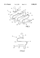
- FIG. 1 is a perspective view of a terminal module including a plurality of one-piece electrical terminals according to the invention
- FIG. 2 is a side elevational view of the terminal module
- FIG. 3 is a top plan view of the terminal module
- FIG. 4 is a front elevational view of the terminal module
- FIG. 5 shows the terminal module mounted in a connector application
- FIG. 6 is a vertical section taken generally along line 6--6 of FIG. 5;
- FIG. 7 shows a plurality of the terminals during fabrication from a length of metal material.
- each terminal is fabricated of a strip of conductive metal material having a short contact portion 14 and a long terminating portion 16.
- the short contact portion is fabricated of a relatively soft metal, as described hereinafter, drawn into a closed-ended cylindrical contact 18.
- Long terminating portion 16 is integral with contact portion 14 and is fabricated of a relatively hard tempered metal, as described hereinafter, formed into a generally S-shaped spring arm as shown clearly in FIGS. 1 and 2.
- each S-shaped spring arm 16 of each terminal 10 is generally planar for surface-mounting on a printed circuit board (not shown).
- overmolded dielectric base 20 includes a plurality of integrally molded mounting posts 24 depending from the underside thereof for insertion into appropriate mounting holes in the printed circuit board.
- terminal module 12 including the one-piece terminals 10, is shown mounted on a printed circuit board 26.
- FIG. 6 shows distal ends 22 of the terminals surface mounted to a top surface 26a of the circuit board, with mounting posts 24 projecting through mounting holes 28 in the board.
- a chassis wall 30 is spaced from but fixed relative to printed circuit board 26.
- the chassis wall has a socket 32 with a through opening 34.
- the closed-ended cylindrical contacts 18, along with the top of the S-shaped spring arms 16 of terminals 10 project upwardly through openings 34 as best seen in FIG. 6.
- An elastomeric sealing grommet 36 is press fit within socket 32 of chassis wall 30.
- the grommet has three holes 38 through which cylindrical contacts 18 of the terminals project. Therefore, the grommet seals with the cylindrical contacts within the peripheries of holes 38, and the grommet seals with the interior of socket 32 about the periphery of the grommet.
- the grommet seals the interior 40 of the enclosure from the exterior thereof.
- S-shaped spring arms 16 functioning to spring-load cylindrical contacts 18, the contacts can move in the direction of double-headed "A" (FIG. 6) within holes 38 in sealing grommet 36.
- the connector application shown in FIGS. 5 and 6 could be a battery connector assembly wherein the outside 42 of chassis wall 30 forms the battery side of the connector assembly, and terminals 10 form electrical interconnections between the battery terminals and circuit traces on printed circuit board 26.
- FIG. 7 illustrates how terminals 10 (FIGS. 1-6) are fabricated from a plurality of strips, generally designated 44, stamped out of a continuous sheet of metal material, generally designated 46.
- the sheet can be a bi-metal sheet or a singular metal sheet. In either alternative, the sheet has a first portion 48 fabricated of a relatively soft material which can be deep drawn to form closed-ended cylindrical contacts 18.
- a second portion 50 of sheet 46 is fabricated of a relatively hard tempered material which can be formed into S-shaped spring arms 16. The two portions 48 and 50 are integrally joined, as at 52.
- first portion 48 can be fabricated of a copper material
- relatively hard second portion 50 can be fabricated of a phosphorus-bronze material, for instance.
- the two different metal portions are integrally joined by a laser weld at 52.
- the copper material of first portion 48 can be drawn into the closed-ended cylindrical contact configuration of contacts 18.
- the harder phosphorus-bronze material of second portion 50 can be formed into the S-shaped spring arms 16.
- sheet 46 also can be fabricated of a singular metal material such as of copper, brass or the like. With the singular material, second portion 50 of strip 46 is selectively treated by a strain hardening process so that the sheet is spring-hardened from edge 46a to line 52, leaving portion 48 in a softer state for drawing into contacts 18.
- a bi-metal sheet 46 or a singular metal sheet 46 With either a bi-metal sheet 46 or a singular metal sheet 46, the sheet is run through a series of stamping stations wherein strips 44 are stamped and contacts 18 are drawn, leaving distal ends 22 of the terminals still attached to a carrier strip 54 of the sheet material. The strips then are fed to forming stations whereat the S-shaped spring arms 16 are formed. When the terminals are severed from carrier strip 54, the terminals will have drawn contacts 18 and terminating distal ends 22 at opposite ends of the S-shaped arms. If the terminals are to be used in a terminal module, such as module 12 described above, three or more of the terminals may remain attached to carrier strip 54 while the terminals are fed to a molding station for overmolding dielectric base 20, whereafter carrier strip 54 can be removed.
Landscapes
- Coupling Device And Connection With Printed Circuit (AREA)
- Manufacturing Of Electrical Connectors (AREA)
Abstract
A one-piece electrical terminal (10) includes a strip (44) of conductive metal material having a contact portion (14) and a terminating portion (16). The contact portion (14) is fabricated of a relatively soft metal drawn into a shaped contact (18). The terminating portion (16) is integral with the contact portion (14) and is fabricated of a relatively hard tempered metal formed into a spring arm (16) supporting the contact (18).
Description
This invention generally relates to the art of electrical connectors and, particularly, to a one-piece electrical terminal.
Generally, electrical connectors include some form of dielectric housing or chassis for mounting one or more conductive electrical terminals. Typically, the terminals have a contact end and a terminating end. The terminating end is electrically terminated to conductors with which the connector is electrically associated. The contact end is adapted for engaging a contact of an appropriate mating connector or other mating electronic device. The terminating end of the terminal(s) can be terminated to a discrete electrical wire or to circuit traces on a printed circuit board, for instance.
In some connector applications, it is desirable or necessary to spring-load at least the contact end or portion of the terminal(s). This can be accomplished by fabricating a portion of the terminal with hard or spring tempered metal and then forming the terminal portion into a spring configuration. Another approach is to fabricate the terminal as a multi-part component wherein the spring is a separate part of the terminal assembly. An example of the latter type of terminal is a "pogo-pin" terminal which typically is fabricated of three parts, namely a housing for a separate spring which biases a separate contact end of the terminal. Such multi-part terminals create problems in both the cost of the assembly as well as its reliability.
In other connector applications, terminals are used in sealed environments, such as in battery connector applications. In other words, a spring-loaded terminal contact may project through a sealing grommet and move relative thereto while maintaining a seal with the grommet. In such applications, the contact end or portion of the terminal often is a closed-ended or dome-shaped structure which can be readily sealed about the periphery thereof. A multi-part "pogo-pin" terminal assembly often is used in such applications notwithstanding the problems mentioned above.
The present invention is directed to solving the various problems discussed above by a one-piece electrical terminal which is both spring loaded and includes an easily sealable contact end, such as a dome-shaped end.
An object, therefore, of the invention is to provide a new and improved, one-piece electrical terminal of the character described.
In the exemplary embodiment of the invention, the terminal includes a strip of conductive metal material having a short contact portion and a long terminating portion. The short contact portion is fabricated of a relatively soft metal which is drawn into a shaped contact. The long terminating portion is integral with the contact portion and is fabricated of a relatively hard tempered metal which is formed into a spring arm supporting the contact.
As disclosed herein, the contact portion of the one-piece terminal is deep drawn into a closed-ended cylindrical contact configuration. The terminating portion is formed into a generally S-shaped spring arm. The distal end of the terminating portion can be generally planar for surface-mounting on a printed circuit board.
In one embodiment of the invention, the conductive metal strip is an integral bi-metal strip, with the short contact portion being of a relatively soft first metal integrally joined to the long terminating portion which is of a relatively hard second metal. For instance, the first portion may be fabricated of a copper material and the second portion may be fabricated of a phosphorous-bronze material.
In another embodiment, the conductive metal strip is fabricated of a singular metal material with the terminating portion being selectively strain hardened. For example, the strip may be fabricated of copper or brass.
Other objects, features and advantages of the invention will be apparent from the following detailed description taken in connection with the accompanying drawings.
The features of this invention which are believed to be novel are set forth with particularity in the appended claims. The invention, together with its objects and the advantages thereof, may be best understood by reference to the following description taken in conjunction with the accompanying drawings, in which like reference numerals identify like elements in the figures and in which:
FIG. 1 is a perspective view of a terminal module including a plurality of one-piece electrical terminals according to the invention;
FIG. 2 is a side elevational view of the terminal module;
FIG. 3 is a top plan view of the terminal module;
FIG. 4 is a front elevational view of the terminal module;
FIG. 5 shows the terminal module mounted in a connector application;
FIG. 6 is a vertical section taken generally along line 6--6 of FIG. 5; and
FIG. 7 shows a plurality of the terminals during fabrication from a length of metal material.
Referring to the drawings in greater detail, and first to FIGS. 1-4, the invention is embodied in a one-piece electrical terminal, generally designated 10, which is shown in the drawings as one of three terminals of a terminal module, generally designated 12. Each terminal is fabricated of a strip of conductive metal material having a short contact portion 14 and a long terminating portion 16. The short contact portion is fabricated of a relatively soft metal, as described hereinafter, drawn into a closed-ended cylindrical contact 18. Long terminating portion 16 is integral with contact portion 14 and is fabricated of a relatively hard tempered metal, as described hereinafter, formed into a generally S-shaped spring arm as shown clearly in FIGS. 1 and 2. Whereas one end of the S-shaped spring arm 16 is integral with contact 18, the opposite end of the S-shaped spring arms of all of the terminals are embedded in a dielectric base 20. The dielectric base may be of plastic material and overmolded about the ends of the S-shaped spring arms of the terminals. A distal end 22 of each S-shaped spring arm 16 of each terminal 10 is generally planar for surface-mounting on a printed circuit board (not shown). To that end, overmolded dielectric base 20 includes a plurality of integrally molded mounting posts 24 depending from the underside thereof for insertion into appropriate mounting holes in the printed circuit board.
Referring to FIGS. 5 and 6, terminal module 12, including the one-piece terminals 10, is shown mounted on a printed circuit board 26. FIG. 6 shows distal ends 22 of the terminals surface mounted to a top surface 26a of the circuit board, with mounting posts 24 projecting through mounting holes 28 in the board.
In the connector application of FIGS. 5 and 6, a chassis wall 30 is spaced from but fixed relative to printed circuit board 26. The chassis wall has a socket 32 with a through opening 34. The closed-ended cylindrical contacts 18, along with the top of the S-shaped spring arms 16 of terminals 10 project upwardly through openings 34 as best seen in FIG. 6. An elastomeric sealing grommet 36 is press fit within socket 32 of chassis wall 30. The grommet has three holes 38 through which cylindrical contacts 18 of the terminals project. Therefore, the grommet seals with the cylindrical contacts within the peripheries of holes 38, and the grommet seals with the interior of socket 32 about the periphery of the grommet. Assuming that chassis wall 30 forms an enclosure for the connector application, the grommet seals the interior 40 of the enclosure from the exterior thereof. With S-shaped spring arms 16 functioning to spring-load cylindrical contacts 18, the contacts can move in the direction of double-headed "A" (FIG. 6) within holes 38 in sealing grommet 36. The connector application shown in FIGS. 5 and 6 could be a battery connector assembly wherein the outside 42 of chassis wall 30 forms the battery side of the connector assembly, and terminals 10 form electrical interconnections between the battery terminals and circuit traces on printed circuit board 26.
FIG. 7 illustrates how terminals 10 (FIGS. 1-6) are fabricated from a plurality of strips, generally designated 44, stamped out of a continuous sheet of metal material, generally designated 46. The sheet can be a bi-metal sheet or a singular metal sheet. In either alternative, the sheet has a first portion 48 fabricated of a relatively soft material which can be deep drawn to form closed-ended cylindrical contacts 18. A second portion 50 of sheet 46 is fabricated of a relatively hard tempered material which can be formed into S-shaped spring arms 16. The two portions 48 and 50 are integrally joined, as at 52.
With continuous sheet 46 fabricated of a bi-metal material, relatively soft first portion 48 can be fabricated of a copper material, and relatively hard second portion 50 can be fabricated of a phosphorus-bronze material, for instance. The two different metal portions are integrally joined by a laser weld at 52. The copper material of first portion 48 can be drawn into the closed-ended cylindrical contact configuration of contacts 18. The harder phosphorus-bronze material of second portion 50 can be formed into the S-shaped spring arms 16.
As stated above, sheet 46 also can be fabricated of a singular metal material such as of copper, brass or the like. With the singular material, second portion 50 of strip 46 is selectively treated by a strain hardening process so that the sheet is spring-hardened from edge 46a to line 52, leaving portion 48 in a softer state for drawing into contacts 18.
With either a bi-metal sheet 46 or a singular metal sheet 46, the sheet is run through a series of stamping stations wherein strips 44 are stamped and contacts 18 are drawn, leaving distal ends 22 of the terminals still attached to a carrier strip 54 of the sheet material. The strips then are fed to forming stations whereat the S-shaped spring arms 16 are formed. When the terminals are severed from carrier strip 54, the terminals will have drawn contacts 18 and terminating distal ends 22 at opposite ends of the S-shaped arms. If the terminals are to be used in a terminal module, such as module 12 described above, three or more of the terminals may remain attached to carrier strip 54 while the terminals are fed to a molding station for overmolding dielectric base 20, whereafter carrier strip 54 can be removed.
It will be understood that the invention may be embodied in other specific forms without departing from the spirit or central characteristics thereof. The present examples and embodiments, therefore, are to be considered in all respects as illustrative and not restrictive, and the invention is not to be limited to the details given herein.
Claims (23)
1. A one-piece electrical terminal, comprising:
a strip of conductive metal material having a short contact portion and a long terminating portion,
the short contact portion being fabricated of a relatively soft metal drawn into a shaped contact, and
the long terminating portion being integral with the short contact portion and being fabricated of a relatively hard tempered metal formed into a spring arm supporting the contact.
2. The one-piece electrical terminal of claim 1 wherein said contact portion is drawn into a closed-ended cylindrical contact configuration.
3. The one-piece electrical terminal of claim 1 wherein said terminating portion is formed into a generally S-shaped spring arm.
4. The one-piece electrical terminal of claim 1 wherein a distal end of said terminating portion is generally planar for surface-mounting on a printed circuit board.
5. The one-piece electrical terminal of claim 1 wherein said strip is an integral bi-metal strip with said short contact portion being of a relatively soft first metal integrally joined to the long terminating portion which is of a relatively hard second metal.
6. The one-piece electrical terminal of claim 1 wherein said strip is fabricated of a singular metal material with the terminating portion being selectively strain hardened.
7. The one-piece electrical terminal of claim 6 wherein said strip is fabricated of a copper material.
8. The one-piece electrical terminal of claim 6 wherein said strip is fabricated of a brass material.
9. A one-piece electrical terminal, comprising:
an elongated strip of conductive metal material having a short contact end and a long terminating end,
the short contact end being fabricated of a relatively soft metal drawn into a contact having a close-ended cylindrical configuration, and
the long terminating end being integral with the contact end and being fabricated of a relatively hard tempered metal formed into a generally S-shaped spring arm supporting the contact.
10. The one-piece electrical terminal of claim 9 wherein a distal end of said terminating end is generally planar for surface-mounting on a printed circuit board.
11. The one-piece electrical terminal of claim 9 wherein said strip is an integral bi-metal strip with said short contact end being of a relatively soft first metal integrally joined to the long terminating end which is of a relatively hard second metal.
12. The one-piece electrical terminal of claim 9 wherein said strip is fabricated of a singular metal material with the terminating end being selectively strain hardened.
13. The one-piece electrical terminal of claim 12 wherein said strip is fabricated of a copper material.
14. The one-piece electrical terminal of claim 12 wherein said strip is fabricated of a brass material.
15. The one-piece electrical terminal of claim 1 wherein said contact end is fabricated of a copper material and said terminating end is fabricated of a phosphorus-bronze material.
16. A one-piece electrical terminal, comprising:
a conductive metal structure having first and second portions,
the first portion being fabricated of a relatively soft material drawn into a given shape, and
the second portion being fabricated of a relatively hard tempered material formed into a spring configuration.
17. The one-piece electrical terminal of claim 16 wherein said first portion is drawn into a closed-ended cylindrical shape.
18. The one-piece electrical terminal of claim 16 wherein said second portion is formed into a generally S-shape.
19. The one-piece electrical terminal of claim 16 wherein said structure is fabricated of a singular metal material with the second portion being selectively strain hardened.
20. The one-piece electrical terminal of claim 19 wherein said structure is fabricated of copper material.
21. The one-piece electrical terminal of claim 19 wherein said structure is fabricated of brass material.
22. The one-piece electrical terminal of claim 19 wherein said structure is an integral bi-metal structure with said first portion being of a relatively soft first metal integrally joined to the second portion which is of a relatively hard second metal.
23. The one-piece electrical terminal of claim 22 wherein said first portion is fabricated of a copper material and said second portion is fabricated of a phosphorus-bronze material.
Priority Applications (4)
| Application Number | Priority Date | Filing Date | Title |
|---|---|---|---|
| US09/049,489 US5980335A (en) | 1998-03-27 | 1998-03-27 | Electrical terminal |
| JP07220899A JP3154118B2 (en) | 1998-03-27 | 1999-03-17 | One-piece electrical terminal |
| EP99106015A EP0945937A3 (en) | 1998-03-27 | 1999-03-25 | Electrical terminal |
| CN99104429A CN1230807A (en) | 1998-03-27 | 1999-03-26 | Electrical terminal |
Applications Claiming Priority (1)
| Application Number | Priority Date | Filing Date | Title |
|---|---|---|---|
| US09/049,489 US5980335A (en) | 1998-03-27 | 1998-03-27 | Electrical terminal |
Publications (1)
| Publication Number | Publication Date |
|---|---|
| US5980335A true US5980335A (en) | 1999-11-09 |
Family
ID=21960097
Family Applications (1)
| Application Number | Title | Priority Date | Filing Date |
|---|---|---|---|
| US09/049,489 Expired - Fee Related US5980335A (en) | 1998-03-27 | 1998-03-27 | Electrical terminal |
Country Status (4)
| Country | Link |
|---|---|
| US (1) | US5980335A (en) |
| EP (1) | EP0945937A3 (en) |
| JP (1) | JP3154118B2 (en) |
| CN (1) | CN1230807A (en) |
Cited By (53)
| Publication number | Priority date | Publication date | Assignee | Title |
|---|---|---|---|---|
| US6165002A (en) * | 1998-12-30 | 2000-12-26 | Garmin Corporation | Electrical connector apparatus |
| WO2002027870A1 (en) * | 2000-09-25 | 2002-04-04 | Avx Corporation | Electrical connector |
| US6497218B2 (en) * | 2001-02-28 | 2002-12-24 | Robert Bosch Corporation | Fuel injector module |
| US20030132102A1 (en) * | 2002-01-12 | 2003-07-17 | Taiwan Semiconductor Manufacturing Co., Ltd. | Cathode contact pin for an electroplating process |
| US20040253846A1 (en) * | 2003-06-11 | 2004-12-16 | Epic Technology Inc. | Land grid array connector including heterogeneous contact elements |
| US20050006356A1 (en) * | 2001-12-28 | 2005-01-13 | Abb Service Srl | Method for welding contact plates and contact elements obtained with the method |
| US20050026510A1 (en) * | 2003-07-31 | 2005-02-03 | J.S.T. Mfg. Co., Ltd. | Electric connector |
| US20050051138A1 (en) * | 2003-09-08 | 2005-03-10 | Robert Bosch Corporation | Intake manifold assembly |
| US20060057900A1 (en) * | 2004-09-08 | 2006-03-16 | Lawrence Rodney A | Apparatus and method for interconnecting a child seat and monitoring system |
| US7025601B2 (en) | 2004-03-19 | 2006-04-11 | Neoconix, Inc. | Interposer and method for making same |
| US20060111821A1 (en) * | 2004-08-09 | 2006-05-25 | Wallner Edward J | Child restraint system comprising event data recorder, and method for providing data relating to installation or adjustment |
| US7056131B1 (en) | 2003-04-11 | 2006-06-06 | Neoconix, Inc. | Contact grid array system |
| US7090503B2 (en) | 2004-03-19 | 2006-08-15 | Neoconix, Inc. | Interposer with compliant pins |
| US20060205284A1 (en) * | 2003-01-20 | 2006-09-14 | Mark Wells | Electrical connector |
| US7113408B2 (en) | 2003-06-11 | 2006-09-26 | Neoconix, Inc. | Contact grid array formed on a printed circuit board |
| US20070066129A1 (en) * | 2005-09-16 | 2007-03-22 | Chih-Wei Chien | Conductive contact and electronic apparatus employing the same |
| US7244125B2 (en) | 2003-12-08 | 2007-07-17 | Neoconix, Inc. | Connector for making electrical contact at semiconductor scales |
| US7347698B2 (en) | 2004-03-19 | 2008-03-25 | Neoconix, Inc. | Deep drawn electrical contacts and method for making |
| US7354276B2 (en) | 2004-07-20 | 2008-04-08 | Neoconix, Inc. | Interposer with compliant pins |
| US7357644B2 (en) | 2005-12-12 | 2008-04-15 | Neoconix, Inc. | Connector having staggered contact architecture for enhanced working range |
| US7371073B2 (en) | 2003-04-11 | 2008-05-13 | Neoconix, Inc. | Contact grid array system |
| US20080124978A1 (en) * | 2006-11-29 | 2008-05-29 | Lotes Co., Ltd. | Electrical connector |
| US7383632B2 (en) | 2004-03-19 | 2008-06-10 | Neoconix, Inc. | Method for fabricating a connector |
| DE102007012500A1 (en) * | 2007-03-15 | 2008-09-18 | Continental Automotive Gmbh | Contacting device for contacting circuit boards comprises electrical conductors coupled with an electrically insulating coupling body so that the ends of the conductors protrude from the coupling body |
| US20090169046A1 (en) * | 2007-12-27 | 2009-07-02 | Chi Mei Communication Systems, Inc. | Electronic device with a speaker |
| US7587817B2 (en) | 2003-04-11 | 2009-09-15 | Neoconix, Inc. | Method of making electrical connector on a flexible carrier |
| US7597561B2 (en) | 2003-04-11 | 2009-10-06 | Neoconix, Inc. | Method and system for batch forming spring elements in three dimensions |
| US20090290744A1 (en) * | 2008-05-21 | 2009-11-26 | Chi Mei Communication Systems, Inc. | Electronic device with a speaker |
| US7628617B2 (en) | 2003-06-11 | 2009-12-08 | Neoconix, Inc. | Structure and process for a contact grid array formed in a circuitized substrate |
| US20100037761A1 (en) * | 2004-04-16 | 2010-02-18 | Bae Systems Survivability Systems, Llc | Lethal Threat Protection System For A Vehicle And Method |
| US7758351B2 (en) | 2003-04-11 | 2010-07-20 | Neoconix, Inc. | Method and system for batch manufacturing of spring elements |
| US20120060919A1 (en) * | 2007-11-12 | 2012-03-15 | Multi-Holding Ag | Junction box for a photovoltaic solar panel |
| US20130035003A1 (en) * | 2010-04-14 | 2013-02-07 | Erich Frank | Electrical plug-in connector element and plug-in connector part comprising a plurality of plug-in connector elements |
| US20130035006A1 (en) * | 2011-08-03 | 2013-02-07 | Samsung Electronics Co., Ltd. | Contact terminal |
| US20130090021A1 (en) * | 2011-10-05 | 2013-04-11 | Fujitsu Limited | Connection member, socket module, socket and method for manufacturing connection member |
| US8584353B2 (en) | 2003-04-11 | 2013-11-19 | Neoconix, Inc. | Method for fabricating a contact grid array |
| US8641428B2 (en) | 2011-12-02 | 2014-02-04 | Neoconix, Inc. | Electrical connector and method of making it |
| US20150099376A1 (en) * | 2013-10-07 | 2015-04-09 | Japan Aviation Electronics Industry, Limited | Connector |
| US20150111400A1 (en) * | 2013-10-18 | 2015-04-23 | Japan Aviation Electronics Industry, Limited | Connector |
| US20170054235A1 (en) * | 2014-04-30 | 2017-02-23 | Conti Temic Microelectronic Gmbh | Contact Element For An Electrical Connection |
| EP3142193A1 (en) * | 2015-09-08 | 2017-03-15 | Apple Inc. | Low-profile spring-loaded contacts |
| US9614313B2 (en) | 2013-08-29 | 2017-04-04 | Japan Aviation Electronics Industry, Ltd. | Electrical connector having a contact with a fixing part press-fitted within a housing |
| US9680273B2 (en) | 2013-03-15 | 2017-06-13 | Neoconix, Inc | Electrical connector with electrical contacts protected by a layer of compressible material and method of making it |
| US9778705B2 (en) | 2015-09-04 | 2017-10-03 | Apple Inc. | Electronic device with moveable contacts at an exterior surface |
| US9948018B2 (en) | 2015-09-08 | 2018-04-17 | Apple Inc. | Low-profile power and data contacts |
| US9977460B2 (en) | 2015-09-04 | 2018-05-22 | Apple Inc. | Electronic device with contacts flush with housing |
| DE102016014986A1 (en) * | 2016-12-15 | 2018-06-21 | e.solutions GmbH | Electrical connection element, docking station and vehicle |
| US10211555B2 (en) * | 2016-02-26 | 2019-02-19 | Arista Networks, Inc. | Method and apparatus to mitigate assembly torsion |
| US20190058271A1 (en) * | 2016-02-04 | 2019-02-21 | Amotech Co., Ltd. | Clip-type contactor and protective apparatus including same |
| US10224661B2 (en) | 2015-09-08 | 2019-03-05 | Apple Inc. | Low-profile spring-loaded contacts |
| US10707627B2 (en) | 2017-09-29 | 2020-07-07 | Apple Inc. | Hybrid connector |
| US20230039986A1 (en) * | 2021-08-09 | 2023-02-09 | Lotes Co., Ltd | Electrical connector and method of manufacturing the same |
| US20230087891A1 (en) * | 2021-09-23 | 2023-03-23 | Apple Inc. | Pass-through connectors for connector systems |
Families Citing this family (6)
| Publication number | Priority date | Publication date | Assignee | Title |
|---|---|---|---|---|
| JP3520468B2 (en) * | 2000-06-21 | 2004-04-19 | 日本航空電子工業株式会社 | connector |
| DE102007009205B3 (en) * | 2007-02-26 | 2008-06-12 | Siemens Home And Office Communication Devices Gmbh & Co. Kg | Electromechanical contact system for mechanical contact force, has spring contact with contact head and stationary counter contact with another contact head |
| JP5943647B2 (en) * | 2012-02-29 | 2016-07-05 | 日本航空電子工業株式会社 | Electrical connector |
| JP6071448B2 (en) | 2012-11-13 | 2017-02-01 | 矢崎総業株式会社 | connector |
| KR102118176B1 (en) * | 2013-12-13 | 2020-06-09 | 삼성전자주식회사 | Contact Clip for Electric Apparatus and Electric Apparatus Comprising the Same |
| CN116191111A (en) * | 2021-11-29 | 2023-05-30 | 上海莫仕连接器有限公司 | magnetic connector |
Citations (7)
| Publication number | Priority date | Publication date | Assignee | Title |
|---|---|---|---|---|
| US4413874A (en) * | 1981-02-27 | 1983-11-08 | Williams Robert A | Multiple contact testing device |
| US4778404A (en) * | 1983-12-27 | 1988-10-18 | Amp Incorporated | Spring terminal |
| US5151643A (en) * | 1991-03-04 | 1992-09-29 | Motorola, Inc. | Integral hang-up and battery charging apparatus |
| US5350322A (en) * | 1990-02-22 | 1994-09-27 | Yazaki Corporation | Bulb socket terminal |
| US5540599A (en) * | 1992-11-11 | 1996-07-30 | Elco Europe Limited | Electrical connector |
| US5664973A (en) * | 1995-01-05 | 1997-09-09 | Motorola, Inc. | Conductive contact |
| US5713765A (en) * | 1996-04-23 | 1998-02-03 | Nugent; Steven F. | High-current audio connector |
Family Cites Families (4)
| Publication number | Priority date | Publication date | Assignee | Title |
|---|---|---|---|---|
| JPS5141222B2 (en) * | 1972-12-06 | 1976-11-09 | ||
| US5511996A (en) * | 1994-11-14 | 1996-04-30 | A.W. Industries, Inc. | Connector contact and method |
| US5658175A (en) * | 1995-10-05 | 1997-08-19 | Itt Corporation | One-piece hooded socket contact and method of producing same |
| WO1997045900A1 (en) * | 1996-05-31 | 1997-12-04 | The Whitaker Corporation | Rechargeable battery connector |
-
1998
- 1998-03-27 US US09/049,489 patent/US5980335A/en not_active Expired - Fee Related
-
1999
- 1999-03-17 JP JP07220899A patent/JP3154118B2/en not_active Expired - Fee Related
- 1999-03-25 EP EP99106015A patent/EP0945937A3/en not_active Withdrawn
- 1999-03-26 CN CN99104429A patent/CN1230807A/en active Pending
Patent Citations (7)
| Publication number | Priority date | Publication date | Assignee | Title |
|---|---|---|---|---|
| US4413874A (en) * | 1981-02-27 | 1983-11-08 | Williams Robert A | Multiple contact testing device |
| US4778404A (en) * | 1983-12-27 | 1988-10-18 | Amp Incorporated | Spring terminal |
| US5350322A (en) * | 1990-02-22 | 1994-09-27 | Yazaki Corporation | Bulb socket terminal |
| US5151643A (en) * | 1991-03-04 | 1992-09-29 | Motorola, Inc. | Integral hang-up and battery charging apparatus |
| US5540599A (en) * | 1992-11-11 | 1996-07-30 | Elco Europe Limited | Electrical connector |
| US5664973A (en) * | 1995-01-05 | 1997-09-09 | Motorola, Inc. | Conductive contact |
| US5713765A (en) * | 1996-04-23 | 1998-02-03 | Nugent; Steven F. | High-current audio connector |
Cited By (86)
| Publication number | Priority date | Publication date | Assignee | Title |
|---|---|---|---|---|
| US6165002A (en) * | 1998-12-30 | 2000-12-26 | Garmin Corporation | Electrical connector apparatus |
| WO2002027870A1 (en) * | 2000-09-25 | 2002-04-04 | Avx Corporation | Electrical connector |
| US6497218B2 (en) * | 2001-02-28 | 2002-12-24 | Robert Bosch Corporation | Fuel injector module |
| US20050006356A1 (en) * | 2001-12-28 | 2005-01-13 | Abb Service Srl | Method for welding contact plates and contact elements obtained with the method |
| US7592566B2 (en) * | 2001-12-28 | 2009-09-22 | Abb S.P.A. | Method for welding contact plates and contact elements obtained with the method |
| US6860769B2 (en) * | 2002-01-12 | 2005-03-01 | Taiwan Semiconductor Manufacturing Co., Ltd | Cathode contact pin for an electroplating process |
| US20030132102A1 (en) * | 2002-01-12 | 2003-07-17 | Taiwan Semiconductor Manufacturing Co., Ltd. | Cathode contact pin for an electroplating process |
| USRE46904E1 (en) * | 2003-01-20 | 2018-06-19 | Connec Limited | Electrical connector |
| US7329156B2 (en) * | 2003-01-20 | 2008-02-12 | Head Electrical International Pty Ltd. | Electrical connector |
| US20060205284A1 (en) * | 2003-01-20 | 2006-09-14 | Mark Wells | Electrical connector |
| US7758351B2 (en) | 2003-04-11 | 2010-07-20 | Neoconix, Inc. | Method and system for batch manufacturing of spring elements |
| US7587817B2 (en) | 2003-04-11 | 2009-09-15 | Neoconix, Inc. | Method of making electrical connector on a flexible carrier |
| US8584353B2 (en) | 2003-04-11 | 2013-11-19 | Neoconix, Inc. | Method for fabricating a contact grid array |
| US7597561B2 (en) | 2003-04-11 | 2009-10-06 | Neoconix, Inc. | Method and system for batch forming spring elements in three dimensions |
| US7056131B1 (en) | 2003-04-11 | 2006-06-06 | Neoconix, Inc. | Contact grid array system |
| US7371073B2 (en) | 2003-04-11 | 2008-05-13 | Neoconix, Inc. | Contact grid array system |
| US7891988B2 (en) | 2003-04-11 | 2011-02-22 | Neoconix, Inc. | System and method for connecting flat flex cable with an integrated circuit, such as a camera module |
| US7625220B2 (en) | 2003-04-11 | 2009-12-01 | Dittmann Larry E | System for connecting a camera module, or like device, using flat flex cables |
| US7070419B2 (en) * | 2003-06-11 | 2006-07-04 | Neoconix Inc. | Land grid array connector including heterogeneous contact elements |
| US7113408B2 (en) | 2003-06-11 | 2006-09-26 | Neoconix, Inc. | Contact grid array formed on a printed circuit board |
| US7628617B2 (en) | 2003-06-11 | 2009-12-08 | Neoconix, Inc. | Structure and process for a contact grid array formed in a circuitized substrate |
| US20040253846A1 (en) * | 2003-06-11 | 2004-12-16 | Epic Technology Inc. | Land grid array connector including heterogeneous contact elements |
| US20050026510A1 (en) * | 2003-07-31 | 2005-02-03 | J.S.T. Mfg. Co., Ltd. | Electric connector |
| US6935906B2 (en) * | 2003-07-31 | 2005-08-30 | J.S.T.Mfg.Co., Ltd. | Electric connector |
| US20050051138A1 (en) * | 2003-09-08 | 2005-03-10 | Robert Bosch Corporation | Intake manifold assembly |
| US7244125B2 (en) | 2003-12-08 | 2007-07-17 | Neoconix, Inc. | Connector for making electrical contact at semiconductor scales |
| US7989945B2 (en) | 2003-12-08 | 2011-08-02 | Neoconix, Inc. | Spring connector for making electrical contact at semiconductor scales |
| US7347698B2 (en) | 2004-03-19 | 2008-03-25 | Neoconix, Inc. | Deep drawn electrical contacts and method for making |
| US7025601B2 (en) | 2004-03-19 | 2006-04-11 | Neoconix, Inc. | Interposer and method for making same |
| US7383632B2 (en) | 2004-03-19 | 2008-06-10 | Neoconix, Inc. | Method for fabricating a connector |
| US7090503B2 (en) | 2004-03-19 | 2006-08-15 | Neoconix, Inc. | Interposer with compliant pins |
| US7621756B2 (en) | 2004-03-19 | 2009-11-24 | Neoconix, Inc. | Contact and method for making same |
| US7645147B2 (en) | 2004-03-19 | 2010-01-12 | Neoconix, Inc. | Electrical connector having a flexible sheet and one or more conductive connectors |
| US20100037761A1 (en) * | 2004-04-16 | 2010-02-18 | Bae Systems Survivability Systems, Llc | Lethal Threat Protection System For A Vehicle And Method |
| US7354276B2 (en) | 2004-07-20 | 2008-04-08 | Neoconix, Inc. | Interposer with compliant pins |
| US7439866B2 (en) | 2004-08-09 | 2008-10-21 | Delphi Technologies, Inc. | Child restraint system comprising event data recorder, and method for providing data relating to installation or adjustment |
| US20060111821A1 (en) * | 2004-08-09 | 2006-05-25 | Wallner Edward J | Child restraint system comprising event data recorder, and method for providing data relating to installation or adjustment |
| US7288009B2 (en) * | 2004-09-08 | 2007-10-30 | Delphi Technologies, Inc. | Apparatus and method for interconnecting a child seat and monitoring system |
| US20060057900A1 (en) * | 2004-09-08 | 2006-03-16 | Lawrence Rodney A | Apparatus and method for interconnecting a child seat and monitoring system |
| US20070066129A1 (en) * | 2005-09-16 | 2007-03-22 | Chih-Wei Chien | Conductive contact and electronic apparatus employing the same |
| US7361064B2 (en) | 2005-09-16 | 2008-04-22 | Hon Hai Precision Industry Co., Ltd. | Conductive contact and electronic apparatus employing the same |
| US7357644B2 (en) | 2005-12-12 | 2008-04-15 | Neoconix, Inc. | Connector having staggered contact architecture for enhanced working range |
| US20080124978A1 (en) * | 2006-11-29 | 2008-05-29 | Lotes Co., Ltd. | Electrical connector |
| DE102007012500A1 (en) * | 2007-03-15 | 2008-09-18 | Continental Automotive Gmbh | Contacting device for contacting circuit boards comprises electrical conductors coupled with an electrically insulating coupling body so that the ends of the conductors protrude from the coupling body |
| US8500462B2 (en) * | 2007-11-12 | 2013-08-06 | Applied Materials, Inc. | Junction box for a photovoltaic solar panel |
| US9059350B2 (en) | 2007-11-12 | 2015-06-16 | Applied Materials, Inc. | Junction box for a photovoltaic solar panel |
| US20120060919A1 (en) * | 2007-11-12 | 2012-03-15 | Multi-Holding Ag | Junction box for a photovoltaic solar panel |
| US8111867B2 (en) * | 2007-12-27 | 2012-02-07 | Chi Mei Communication Systems, Inc. | Electronic device with a speaker |
| US20090169046A1 (en) * | 2007-12-27 | 2009-07-02 | Chi Mei Communication Systems, Inc. | Electronic device with a speaker |
| US8023681B2 (en) * | 2008-05-21 | 2011-09-20 | Chi Mei Communication Systems, Inc. | Electronic device with a speaker |
| US20090290744A1 (en) * | 2008-05-21 | 2009-11-26 | Chi Mei Communication Systems, Inc. | Electronic device with a speaker |
| US20130035003A1 (en) * | 2010-04-14 | 2013-02-07 | Erich Frank | Electrical plug-in connector element and plug-in connector part comprising a plurality of plug-in connector elements |
| US9004955B2 (en) * | 2010-04-14 | 2015-04-14 | Pfisterer Kontaktsyteme GmbH | Electrical plug-in connector element and plug-in connector part comprising a plurality of plug-in connector elements |
| US20130035006A1 (en) * | 2011-08-03 | 2013-02-07 | Samsung Electronics Co., Ltd. | Contact terminal |
| US8668529B2 (en) * | 2011-08-03 | 2014-03-11 | Samsung Electronics Co., Ltd. | Contact terminal |
| US20130090021A1 (en) * | 2011-10-05 | 2013-04-11 | Fujitsu Limited | Connection member, socket module, socket and method for manufacturing connection member |
| US8911243B2 (en) * | 2011-10-05 | 2014-12-16 | Fujitsu Component Limited | Connection member, socket module, socket and method for manufacturing connection member |
| US8641428B2 (en) | 2011-12-02 | 2014-02-04 | Neoconix, Inc. | Electrical connector and method of making it |
| US9680273B2 (en) | 2013-03-15 | 2017-06-13 | Neoconix, Inc | Electrical connector with electrical contacts protected by a layer of compressible material and method of making it |
| US9614313B2 (en) | 2013-08-29 | 2017-04-04 | Japan Aviation Electronics Industry, Ltd. | Electrical connector having a contact with a fixing part press-fitted within a housing |
| US20150099376A1 (en) * | 2013-10-07 | 2015-04-09 | Japan Aviation Electronics Industry, Limited | Connector |
| US9281584B2 (en) * | 2013-10-07 | 2016-03-08 | Japan Aviation Electronics Industry, Limited | Connector |
| US9379466B2 (en) * | 2013-10-18 | 2016-06-28 | Japan Aviaton Electronics Industry, Limited | Connector |
| US20150111400A1 (en) * | 2013-10-18 | 2015-04-23 | Japan Aviation Electronics Industry, Limited | Connector |
| US9991618B2 (en) * | 2014-04-30 | 2018-06-05 | Conti Temic Microelectronic Gmbh | Contact element for an electrical connection |
| US20170054235A1 (en) * | 2014-04-30 | 2017-02-23 | Conti Temic Microelectronic Gmbh | Contact Element For An Electrical Connection |
| US10579097B2 (en) | 2015-09-04 | 2020-03-03 | Apple Inc. | Electronic device with contacts flush with housing |
| US9778705B2 (en) | 2015-09-04 | 2017-10-03 | Apple Inc. | Electronic device with moveable contacts at an exterior surface |
| US9977460B2 (en) | 2015-09-04 | 2018-05-22 | Apple Inc. | Electronic device with contacts flush with housing |
| US9948018B2 (en) | 2015-09-08 | 2018-04-17 | Apple Inc. | Low-profile power and data contacts |
| EP3142193A1 (en) * | 2015-09-08 | 2017-03-15 | Apple Inc. | Low-profile spring-loaded contacts |
| US10050368B2 (en) | 2015-09-08 | 2018-08-14 | Apple Inc. | Low-profile spring-loaded contacts |
| US10153577B2 (en) | 2015-09-08 | 2018-12-11 | Apple Inc. | Low-profile power and data contacts |
| US9893452B2 (en) | 2015-09-08 | 2018-02-13 | Apple Inc. | Low-profile spring-loaded contacts |
| US10224661B2 (en) | 2015-09-08 | 2019-03-05 | Apple Inc. | Low-profile spring-loaded contacts |
| US10418741B2 (en) | 2015-09-08 | 2019-09-17 | Apple Inc. | Low-profile power and data contacts |
| US10498057B2 (en) * | 2016-02-04 | 2019-12-03 | Amotech Co., Ltd. | Clip-type contactor and protective apparatus including same |
| US20190058271A1 (en) * | 2016-02-04 | 2019-02-21 | Amotech Co., Ltd. | Clip-type contactor and protective apparatus including same |
| US10211555B2 (en) * | 2016-02-26 | 2019-02-19 | Arista Networks, Inc. | Method and apparatus to mitigate assembly torsion |
| DE102016014986A1 (en) * | 2016-12-15 | 2018-06-21 | e.solutions GmbH | Electrical connection element, docking station and vehicle |
| DE102016014986B4 (en) * | 2016-12-15 | 2025-11-27 | e.solutions GmbH | Electrical connector, docking station and vehicle |
| US10707627B2 (en) | 2017-09-29 | 2020-07-07 | Apple Inc. | Hybrid connector |
| US20230039986A1 (en) * | 2021-08-09 | 2023-02-09 | Lotes Co., Ltd | Electrical connector and method of manufacturing the same |
| US12199371B2 (en) * | 2021-08-09 | 2025-01-14 | Lotes Co., Ltd | Electrical connector and method of manufacturing the same |
| US20230087891A1 (en) * | 2021-09-23 | 2023-03-23 | Apple Inc. | Pass-through connectors for connector systems |
| US12327941B2 (en) * | 2021-09-23 | 2025-06-10 | Apple Inc. | Pass-through connectors for connector systems |
Also Published As
| Publication number | Publication date |
|---|---|
| JPH11329634A (en) | 1999-11-30 |
| CN1230807A (en) | 1999-10-06 |
| JP3154118B2 (en) | 2001-04-09 |
| EP0945937A3 (en) | 2000-11-29 |
| EP0945937A2 (en) | 1999-09-29 |
Similar Documents
| Publication | Publication Date | Title |
|---|---|---|
| US5980335A (en) | Electrical terminal | |
| US10756466B2 (en) | Connector | |
| EP0590517B1 (en) | Electrical connector with preloaded spring-like terminal with improved wiping action | |
| US6574855B1 (en) | Method of making a switch-equipped coaxial connector | |
| US6540529B1 (en) | Electrical connector assembly | |
| US20030199195A1 (en) | Electrical connector assembly and module incorporating the same | |
| US11196207B2 (en) | Card edge connector with protective cover | |
| EP0631344B1 (en) | Sealed insulation displacement connector | |
| WO2002035662A1 (en) | Filtered electrical connector | |
| IE80506B1 (en) | Electrical connector with contact anti-overstress means | |
| US7029287B2 (en) | Electrical connector in which a wiping action is carried out in a narrow area | |
| KR20040103766A (en) | Electrical connector and method of producing the same | |
| EP0047095A2 (en) | A connector for a leadless electronic package | |
| WO2009010704A1 (en) | An electrical unit | |
| EP1276181B1 (en) | Electrical connector for receiving a plug | |
| US20040166707A1 (en) | Electrical connector having a holddown for ground connection | |
| US6336820B2 (en) | Switch-equipped coaxial connector | |
| EP1009075A3 (en) | Electrical contact and bandolier assembly | |
| JPH06260238A (en) | Connecting terminal | |
| US6109932A (en) | Three-dimensional electrical interconnection system | |
| US6257903B1 (en) | Self-docking electrical connector | |
| KR100629814B1 (en) | Connector locating and retaining device for printed wiring board application | |
| JP4212012B2 (en) | connector | |
| JP2958865B2 (en) | Crimpable electrical terminals | |
| KR20180031468A (en) | Press-fit type electric terminal structure |
Legal Events
| Date | Code | Title | Description |
|---|---|---|---|
| AS | Assignment |
Owner name: MOLEX INCORPORATED, ILLINOIS Free format text: ASSIGNMENT OF ASSIGNORS INTEREST;ASSIGNORS:BARBIERI, SILVIO;MARTUCCI, ROBERTO;REEL/FRAME:009130/0172 Effective date: 19980317 |
|
| REMI | Maintenance fee reminder mailed | ||
| LAPS | Lapse for failure to pay maintenance fees | ||
| STCH | Information on status: patent discontinuation |
Free format text: PATENT EXPIRED DUE TO NONPAYMENT OF MAINTENANCE FEES UNDER 37 CFR 1.362 |
|
| FP | Lapsed due to failure to pay maintenance fee |
Effective date: 20031109 |