CN1230807A - Electrical terminal - Google Patents
Electrical terminal Download PDFInfo
- Publication number
- CN1230807A CN1230807A CN99104429A CN99104429A CN1230807A CN 1230807 A CN1230807 A CN 1230807A CN 99104429 A CN99104429 A CN 99104429A CN 99104429 A CN99104429 A CN 99104429A CN 1230807 A CN1230807 A CN 1230807A
- Authority
- CN
- China
- Prior art keywords
- electric connection
- type electric
- integral type
- metal
- contact
- Prior art date
- Legal status (The legal status is an assumption and is not a legal conclusion. Google has not performed a legal analysis and makes no representation as to the accuracy of the status listed.)
- Pending
Links
Images


Classifications
-
- H—ELECTRICITY
- H01—ELECTRIC ELEMENTS
- H01R—ELECTRICALLY-CONDUCTIVE CONNECTIONS; STRUCTURAL ASSOCIATIONS OF A PLURALITY OF MUTUALLY-INSULATED ELECTRICAL CONNECTING ELEMENTS; COUPLING DEVICES; CURRENT COLLECTORS
- H01R13/00—Details of coupling devices of the kinds covered by groups H01R12/70 or H01R24/00 - H01R33/00
- H01R13/02—Contact members
- H01R13/22—Contacts for co-operating by abutting
- H01R13/24—Contacts for co-operating by abutting resilient; resiliently-mounted
- H01R13/2442—Contacts for co-operating by abutting resilient; resiliently-mounted with a single cantilevered beam
-
- H—ELECTRICITY
- H01—ELECTRIC ELEMENTS
- H01R—ELECTRICALLY-CONDUCTIVE CONNECTIONS; STRUCTURAL ASSOCIATIONS OF A PLURALITY OF MUTUALLY-INSULATED ELECTRICAL CONNECTING ELEMENTS; COUPLING DEVICES; CURRENT COLLECTORS
- H01R12/00—Structural associations of a plurality of mutually-insulated electrical connecting elements, specially adapted for printed circuits, e.g. printed circuit boards [PCB], flat or ribbon cables, or like generally planar structures, e.g. terminal strips, terminal blocks; Coupling devices specially adapted for printed circuits, flat or ribbon cables, or like generally planar structures; Terminals specially adapted for contact with, or insertion into, printed circuits, flat or ribbon cables, or like generally planar structures
- H01R12/70—Coupling devices
- H01R12/71—Coupling devices for rigid printing circuits or like structures
- H01R12/712—Coupling devices for rigid printing circuits or like structures co-operating with the surface of the printed circuit or with a coupling device exclusively provided on the surface of the printed circuit
- H01R12/716—Coupling device provided on the PCB
-
- H—ELECTRICITY
- H01—ELECTRIC ELEMENTS
- H01R—ELECTRICALLY-CONDUCTIVE CONNECTIONS; STRUCTURAL ASSOCIATIONS OF A PLURALITY OF MUTUALLY-INSULATED ELECTRICAL CONNECTING ELEMENTS; COUPLING DEVICES; CURRENT COLLECTORS
- H01R13/00—Details of coupling devices of the kinds covered by groups H01R12/70 or H01R24/00 - H01R33/00
- H01R13/02—Contact members
- H01R13/03—Contact members characterised by the material, e.g. plating, or coating materials
-
- H—ELECTRICITY
- H01—ELECTRIC ELEMENTS
- H01R—ELECTRICALLY-CONDUCTIVE CONNECTIONS; STRUCTURAL ASSOCIATIONS OF A PLURALITY OF MUTUALLY-INSULATED ELECTRICAL CONNECTING ELEMENTS; COUPLING DEVICES; CURRENT COLLECTORS
- H01R13/00—Details of coupling devices of the kinds covered by groups H01R12/70 or H01R24/00 - H01R33/00
- H01R13/02—Contact members
- H01R13/22—Contacts for co-operating by abutting
- H01R13/24—Contacts for co-operating by abutting resilient; resiliently-mounted
- H01R13/2464—Contacts for co-operating by abutting resilient; resiliently-mounted characterized by the contact point
- H01R13/2471—Contacts for co-operating by abutting resilient; resiliently-mounted characterized by the contact point pin shaped
Abstract
A one-piece electrical terminal (10) includes a strip (44) of conductive metal material having a contact portion (14) and a terminating portion (16). The contact portion (14) is fabricated of a relatively soft metal drawn into a shaped contact (18). The terminating portion (16) is integral with the contact portion (14) and is fabricated of a relatively hard tempered metal formed into a spring arm (16) supporting the contact (18).
Description
Present invention relates in general to the electric connection field, particularly relate to a kind of integral type electric connection.
Usually, electric connector comprises that the insulation shell of certain form or base plate are in order to install one or more conductive contacts.Generally speaking, this joint has a contact jaw and a termination end.This termination end is electrically connected on conductor, and this joint is electrically connected with this conductor.Contact jaw is used for the engage contacts that cooperate joint or other cooperation electronic installation suitable with.The termination end of joint can be connected in single electric wire or be connected in circuit trace on the printed circuit board (PCB) for example.
In the application of some connector, wish or need the spring load contact jaw or the contact portion of joint at least.This can realize by the part of joint is made into the spring shape then with hard or the manufacturing of spring temper metal.Another kind method is that joint is made the parts of being made up of several parts, and its medi-spring is an independent sector of piecing devices.The example of the joint of a kind of pattern in back is a kind of " spring pin " (" pogo-pin ") joint, and it is generally made by three parts, promptly is used for the housing of an independent spring, and this spring bias voltage an independent contact jaw of joint.Such many parts joint is having problems aspect cost that installs and the reliability thereof.
In the application of some other connector, the environment that joint is used for sealing is for example in the application of battery connector.In other words, the joint contact of a spring load can pass a sealing ring and move with respect to it, keeps sealing by sealing ring simultaneously.In these were used, the contact jaw of joint or contact portion usually were a blind end or individual dome-like structures, and this can easily be sealed around its periphery.Many parts " spring pin " piecing devices usually are used for these to be used, although there are the problems referred to above in it.
The objective of the invention is to solve above-mentioned variety of issue with a kind of integral type electric connection, this integral type electric connection be spring load comprise the contact jaw that is easy to seal again, as dome-shaped end.
Therefore, an object of the present invention is to provide a kind of new-type and improved integral type electric connection with above-mentioned feature.
In exemplary embodiment of the present invention, joint comprises the band that conductive metallic material is made, and this band has a short contact part and a long termination portion.Short contact is partly used than the soft metal and is made, and it is drawn into a contact that is shaped.Long termination portion and described contact site are divided into whole and with harder tempered metal manufacturing, are made into the spring arm that supports contact.
As disclosed in this, the contact portion of integral joint is become the cylinder contact shape of blind end by deep-drawing.Termination portion is made S-shaped substantially spring arm.The end of termination portion can be substantially the plane so that be surface mounted on the printed circuit board (PCB).
In one embodiment of the invention, conductive metal band is holistic bimetallic strip, by the softer first metal short contact part with connect into integral body by the second harder metal long termination portion.For example, first's available copper made and second portion can be used phosphorus-bronze material manufacturing.
In another embodiment, conductive metal band is planted the metal material manufacturing with a list, and its termination portion is through optionally strain hardening.For example, this band can be with copper or brass manufacturing.
Other purposes of the present invention, feature and advantage will be apparent by following detailed description with reference to accompanying drawing.
The feature that is considered to have novelty among the present invention at length is set forth in the appended claims.The present invention and purpose thereof and advantage can be understood best by consulting in the following description about accompanying drawing, and wherein same label is represented same element in each figure, wherein:
Fig. 1 is the perspective view of an adapter assembly, and it comprises a plurality of integral type electric connection of the present invention;
Fig. 2 is the end view of adapter assembly;
Fig. 3 is the top view of adapter assembly;
Fig. 4 is the front view of adapter assembly;
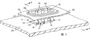
Fig. 5 illustrates the adapter assembly that is installed in the connector application;
Fig. 6 is the vertical cross section that roughly intercepts along Fig. 5 center line 6-6; And
Fig. 7 illustrates a plurality of joints of being made by one section metal material.
With reference to accompanying drawing, at first with reference to Fig. 1-4, the present invention is embodied in the integral type electric connection in more detail, and it represents with 10 that totally it is as overall shown in the drawings with one of them joint of three joints in 12 adapter assemblies of representing.The band manufacturing of conductive metallic material of each joint, it has a short contact part 14 and a long termination portion 16.This short contact is partly used softer metal manufacturing, as described below, it is drawn into the cylinder contact 18 of blind end.Long termination portion 16 is whole also with harder tempered metal manufacturing with 14 one-tenth of contact portions, as described below, is made into S-shaped substantially spring arm, as being clearly shown that among Fig. 1 and 2.Although an end of S shape spring arm 16 is whole with 18 one-tenth of contacts, all the end opposite of the S shape spring arm of joint all embeds in the base plate 20 of an insulation.The base plate of this insulation can be plastics and around the end overmolding of the S of each joint shape spring arm.The end 22 of each S shape spring arm 16 of each joint 10 be substantially the plane so that be surface mounted on the printed circuit board (PCB) (not shown).For this reason, the insulating base 20 of overmolding comprise by its down the erection column 24 of the one-tenth integral molded plastic of cross hang so that insert in the suitable installing hole in the printed circuit board (PCB).
With reference to Fig. 5 and 6, comprise shown in the figure that the adapter assembly 12 of each integral joint 10 is installed on the printed circuit board (PCB) 26.Fig. 6 illustrates end 22 mounted on surface of joint in the upper surface 26a of circuit board, and its erection column 24 passes the installing hole 28 on the plate.
In the connector of Fig. 5 and 6 was used, base plate wall 30 and printed circuit board (PCB) 26 were spaced apart but fix with respect to printed circuit board (PCB) 26.This base plate wall has the dimple 32 of band through hole 34.The cylinder contact 18 of blind end is upward through through hole 34 with the top of the S shape spring arm 16 of joint 10, as being clear that among Fig. 6.Elastomeric seal circle 36 presses fit in the dimple 32 of base plate wall 30.The sealing circle has three holes 38, and the cylinder contact 18 of each joint passes these holes.Therefore, sealing ring is the sealing cylinder contact in the periphery in each hole 38, and sealing ring is around the inboard of its periphery sealing dimple 32.Suppose that base plate wall 30 constitutes a closure member in the connector application, the then inboard 40 of sealing ring this closure member of side seal outside it.By the effect of the cylinder contact 18 of 16 pairs of spring loads of S shape spring arm, each contact can the direction along double-head arrow " A " move (Fig. 6) in the hole 38 of sealing ring 36.It can be the battery connector device that connector shown in Fig. 5 and 6 is used, and wherein the outside 42 of base plate wall 30 forms the battery side of piecing devices, and joint 10 forms mutual electrical connection the between the circuit trace on battery contacts and the printed circuit board (PCB) 26.
Fig. 7 illustrates how joint 10 (Fig. 1~6) is made by a plurality of bands, and each band represents with 44 that totally the continuous metal panel material that these bands are represented with overall usefulness 46 is stamped to form.This plate can be bimetallic plates or monometallic plate.In each scheme, this plate has uses the first 48 that makes than soft material, and it can be through deep-drawing to form the cylinder contact 18 of blind end.The harder tempering made of second portion 50 usefulness of plate 46, it can make S shape spring arm 16.Two parts 48 and 50 are as connecting into integral body at 52 places.
About the continuous slab made from bimetallic material 46, for example, softer first's 48 available copper made, and harder second portion 50 can be used phosphorus-bronze material manufacturing.Two different metals partly connect into integral body with Laser Welding at 52 places.The copper product of first 48 can draw into the blind end cylinder contact shape of contact 18.Harder phosphorus one bronze material of second portion 50 can be made into S shape spring arm 16.
As mentioned above, also available single metal material manufacturing, for example copper, the brass etc. of planting of plate 46.About single material of planting, the second portion 50 with 46 is optionally handled by strain hardening technology so that making it is that elasticity is hardened from edge 46a to line 52, and part 48 is retained under the softer state so that draw into contact 18.
About bimetallic plates or monometallic plate 46, plate operation is through a series of press work platform, wherein respectively is with 44 to be stamped out and contact 18 is drawn and forms, and what the end 22 that stays joint still was connected in sheet material entrusts 54.Each band is sent to the shaping workbench then, forms S shape spring arm 16 there.When each joint being cut off when entrusting 54, each joint will have contact 18 that draws and the termination end 22 that is positioned at S shape arm end opposite.If joint is used for an adapter assembly, above-described assembly 12 for example, a then three or more joint can still be connected in to prop up entrusts 54, simultaneously joint is delivered to the molding workbench so that the base plate 20 of overmolding (overmolding) insulation can remove afterwards to prop up and entrust 54.
Should be appreciated that the present invention can other concrete form embodies and do not break away from its spirit or key character.Therefore, present embodiment and embodiment should be considered to be aspect all illustrative rather than restrictive, and the present invention is not limited to the details that this paper provides.
Claims (23)
1. an integral type electric connection (10) comprising:
The band that conductive metallic material is made (44), it has short contact part (14) and long termination portion (16);
Short contact part (14) is used than the soft metal and is made, and it is drawn into the contact (18) of shaping; And
Long termination portion and described contact site are divided into whole and with harder tempered metal manufacturing, are made into the spring arm (16) that supports contact (18).
2. the integral type electric connection of claim 1 is characterized in that described contact portion (14) is through drawing into the cylinder contact shape (18) of blind end.
3. the integral type electric connection of claim 1 is characterized in that described termination portion makes S-shaped substantially spring arm (16).
4. the integral type electric connection of claim 1, the end (22) that it is characterized in that described termination portion (16) be substantially the plane so that be surface mounted on the printed circuit board (PCB) (26).
5. the integral type electric connection of claim 1 is characterized in that, described band (44) is whole bimetallic strip, by the first softer metal short contact part (14) with connect into integral body by the second harder metal long termination portion (16).
6. the integral type electric connection of claim 1 is characterized in that, described band (44) is planted the metal material manufacturing with list, and its termination portion (16) is by optionally strain hardening.
7. the integral type electric connection of claim 6 is characterized in that described band (44) makes with copper product.
8. the integral type electric connection of claim 6 is characterized in that described band (44) makes with brass material.
9. an integral type electric connection (10) comprising:
A slender tapes made from conductive metallic material (44), it has short circuit contravention (14) and long termination end (16);
Short circuit contravention (14) is used than the soft metal and is made, and it is drawn the contact (18) of the cylindrical configuration that becomes to have blind end; And
Long termination end (16) becomes whole and with harder tempered metal manufacturing, is made into the S-shaped substantially spring arm (16) that supports contact (18) with described contact jaw (14).
10. the integral type electric connection of claim 9, the end (22) that it is characterized in that described termination end (16) be substantially the plane so that be surface mounted on the printed circuit board (PCB) (26).
11. the integral type electric connection of claim 9 is characterized in that, described band (44) is whole bimetallic strip, by the first softer metal short circuit contravention (14) with connect into integral body by the second harder metal long termination end (16).
12. the integral type electric connection of claim 9 is characterized in that, described band (44) is planted the metal material manufacturing with list, and its termination end (16) is by optionally strain hardening.
13. the integral type electric connection of claim 12 is characterized in that described band (44) makes with copper product.
14. the integral type electric connection of claim 12 is characterized in that described band (44) makes with brass material.
15. the integral type electric connection of claim 1 is characterized in that described contact jaw (14) described termination end (16) phosphorus-bronze material manufacturing with the copper product manufacturing.
16. an integral type electric connection (10) comprising:
One has the conductive metal structure (44) of first (14) and second portion (16);
First (14) uses than the soft material manufacturing, and it is drawn into given shape (18); And
Second portion (16) is made into the spring configuration with harder tempering made.
17. the integral type electric connection of claim 16 is characterized in that described first (14) is through drawing the cylindrical shape (18) that forms blind end.
18. the integral type electric connection of claim 16 is characterized in that described second portion (16) makes substantially S shape.
19. the integral type electric connection of claim 16 is characterized in that the single metal material manufacturing of planting of described structure (44), its second portion (16) is by optionally strain hardening.
20. the integral type electric connection of claim 19 is characterized in that described structure (44) makes with copper product.
21. the integral type electric connection of claim 19 is characterized in that described structure (44) makes with brass material.
22. the integral type electric connection of claim 19, it is characterized in that, described structure (44) is a kind of bimetal structure of integral body, by the first softer metal first (14) with connect into integral body by the second harder metal second portion (16).
23. the integral type electric connection of claim 22 is characterized in that described first (14) second portion (16) phosphorus-bronze material manufacturing with the copper product manufacturing.
Applications Claiming Priority (2)
| Application Number | Priority Date | Filing Date | Title |
|---|---|---|---|
| US09/049,489 US5980335A (en) | 1998-03-27 | 1998-03-27 | Electrical terminal |
| US09/049,489 | 1998-03-27 |
Publications (1)
| Publication Number | Publication Date |
|---|---|
| CN1230807A true CN1230807A (en) | 1999-10-06 |
Family
ID=21960097
Family Applications (1)
| Application Number | Title | Priority Date | Filing Date |
|---|---|---|---|
| CN99104429A Pending CN1230807A (en) | 1998-03-27 | 1999-03-26 | Electrical terminal |
Country Status (4)
| Country | Link |
|---|---|
| US (1) | US5980335A (en) |
| EP (1) | EP0945937A3 (en) |
| JP (1) | JP3154118B2 (en) |
| CN (1) | CN1230807A (en) |
Cited By (5)
| Publication number | Priority date | Publication date | Assignee | Title |
|---|---|---|---|---|
| CN100555752C (en) * | 2005-09-16 | 2009-10-28 | 鸿富锦精密工业(深圳)有限公司 | Arrangement for resilient contacting and use the electronic equipment of this arrangement for resilient contacting |
| CN104518315A (en) * | 2013-10-07 | 2015-04-15 | 日本航空电子工业株式会社 | Connector |
| CN104604039A (en) * | 2013-08-29 | 2015-05-06 | 日本航空电子工业株式会社 | Electric connector |
| CN104823331A (en) * | 2012-11-13 | 2015-08-05 | 矢崎总业株式会社 | Connector |
| CN105814747A (en) * | 2013-12-13 | 2016-07-27 | 三星电子株式会社 | Connecting member for electronic device, and electronic device comprising same |
Families Citing this family (52)
| Publication number | Priority date | Publication date | Assignee | Title |
|---|---|---|---|---|
| US6165002A (en) * | 1998-12-30 | 2000-12-26 | Garmin Corporation | Electrical connector apparatus |
| JP3520468B2 (en) | 2000-06-21 | 2004-04-19 | 日本航空電子工業株式会社 | connector |
| AU2001296280A1 (en) * | 2000-09-25 | 2002-04-08 | Avx Corporation | Electrical connector |
| US6497218B2 (en) * | 2001-02-28 | 2002-12-24 | Robert Bosch Corporation | Fuel injector module |
| ITMI20012837A1 (en) * | 2001-12-28 | 2003-06-28 | Abb Service Srl | METHOD FOR WELDING CONTACT PLATES AND CONTACT ELEMENTS OBTAINED BY SUCH METHOD |
| US6860769B2 (en) * | 2002-01-12 | 2005-03-01 | Taiwan Semiconductor Manufacturing Co., Ltd | Cathode contact pin for an electroplating process |
| US7357657B2 (en) * | 2003-01-20 | 2008-04-15 | Head Electrical International, Pty Ltd | Electrical connection device |
| US7056131B1 (en) | 2003-04-11 | 2006-06-06 | Neoconix, Inc. | Contact grid array system |
| US7758351B2 (en) | 2003-04-11 | 2010-07-20 | Neoconix, Inc. | Method and system for batch manufacturing of spring elements |
| US7113408B2 (en) | 2003-06-11 | 2006-09-26 | Neoconix, Inc. | Contact grid array formed on a printed circuit board |
| US7114961B2 (en) | 2003-04-11 | 2006-10-03 | Neoconix, Inc. | Electrical connector on a flexible carrier |
| US7628617B2 (en) | 2003-06-11 | 2009-12-08 | Neoconix, Inc. | Structure and process for a contact grid array formed in a circuitized substrate |
| US7597561B2 (en) | 2003-04-11 | 2009-10-06 | Neoconix, Inc. | Method and system for batch forming spring elements in three dimensions |
| US20070020960A1 (en) | 2003-04-11 | 2007-01-25 | Williams John D | Contact grid array system |
| US8584353B2 (en) | 2003-04-11 | 2013-11-19 | Neoconix, Inc. | Method for fabricating a contact grid array |
| US7244125B2 (en) | 2003-12-08 | 2007-07-17 | Neoconix, Inc. | Connector for making electrical contact at semiconductor scales |
| US7070419B2 (en) * | 2003-06-11 | 2006-07-04 | Neoconix Inc. | Land grid array connector including heterogeneous contact elements |
| JP2005050738A (en) * | 2003-07-31 | 2005-02-24 | Jst Mfg Co Ltd | Electric connector |
| US20050051138A1 (en) * | 2003-09-08 | 2005-03-10 | Robert Bosch Corporation | Intake manifold assembly |
| US7090503B2 (en) | 2004-03-19 | 2006-08-15 | Neoconix, Inc. | Interposer with compliant pins |
| US7347698B2 (en) | 2004-03-19 | 2008-03-25 | Neoconix, Inc. | Deep drawn electrical contacts and method for making |
| US7025601B2 (en) | 2004-03-19 | 2006-04-11 | Neoconix, Inc. | Interposer and method for making same |
| US7383632B2 (en) | 2004-03-19 | 2008-06-10 | Neoconix, Inc. | Method for fabricating a connector |
| US7695053B1 (en) * | 2004-04-16 | 2010-04-13 | Bae Systems Survivability Systems, Llc | Lethal threat protection system for a vehicle and method |
| US7354276B2 (en) | 2004-07-20 | 2008-04-08 | Neoconix, Inc. | Interposer with compliant pins |
| EP1778520B1 (en) * | 2004-08-09 | 2015-08-05 | Delphi Technologies Inc. | Child restraint system comprising event data recorder, and method for providing data relating to installation or adjustment |
| US7288009B2 (en) * | 2004-09-08 | 2007-10-30 | Delphi Technologies, Inc. | Apparatus and method for interconnecting a child seat and monitoring system |
| US7357644B2 (en) | 2005-12-12 | 2008-04-15 | Neoconix, Inc. | Connector having staggered contact architecture for enhanced working range |
| US20080124978A1 (en) * | 2006-11-29 | 2008-05-29 | Lotes Co., Ltd. | Electrical connector |
| DE102007009205B3 (en) * | 2007-02-26 | 2008-06-12 | Siemens Home And Office Communication Devices Gmbh & Co. Kg | Electromechanical contact system for mechanical contact force, has spring contact with contact head and stationary counter contact with another contact head |
| DE102007012500A1 (en) * | 2007-03-15 | 2008-09-18 | Continental Automotive Gmbh | Contacting device for contacting circuit boards comprises electrical conductors coupled with an electrically insulating coupling body so that the ends of the conductors protrude from the coupling body |
| EP2058867A3 (en) | 2007-11-12 | 2009-07-22 | Multi-Holding AG | Junction box for a photovoltaic solar panel |
| CN101472203A (en) * | 2007-12-27 | 2009-07-01 | 深圳富泰宏精密工业有限公司 | Electronic device |
| CN101588395A (en) * | 2008-05-21 | 2009-11-25 | 深圳富泰宏精密工业有限公司 | Electronic device with loudspeaker |
| DE102010014980A1 (en) * | 2010-04-14 | 2011-10-20 | Pfisterer Kontaktsysteme Gmbh | Electrical plug connection element and plug connection part with a plurality of plug connection elements |
| KR101817804B1 (en) * | 2011-08-03 | 2018-01-11 | 삼성전자주식회사 | Contact terminal |
| JP5718203B2 (en) * | 2011-10-05 | 2015-05-13 | 富士通コンポーネント株式会社 | Socket module and socket |
| US8641428B2 (en) | 2011-12-02 | 2014-02-04 | Neoconix, Inc. | Electrical connector and method of making it |
| JP5943647B2 (en) * | 2012-02-29 | 2016-07-05 | 日本航空電子工業株式会社 | Electrical connector |
| US9680273B2 (en) | 2013-03-15 | 2017-06-13 | Neoconix, Inc | Electrical connector with electrical contacts protected by a layer of compressible material and method of making it |
| JP6108462B2 (en) * | 2013-10-18 | 2017-04-05 | 日本航空電子工業株式会社 | connector |
| DE102014208226B4 (en) * | 2014-04-30 | 2020-07-23 | Conti Temic Microelectronic Gmbh | Contact element, circuit arrangement with such a contact element and copper tape for producing a plurality of contact elements |
| US9778705B2 (en) | 2015-09-04 | 2017-10-03 | Apple Inc. | Electronic device with moveable contacts at an exterior surface |
| US10579097B2 (en) | 2015-09-04 | 2020-03-03 | Apple Inc. | Electronic device with contacts flush with housing |
| US9948018B2 (en) | 2015-09-08 | 2018-04-17 | Apple Inc. | Low-profile power and data contacts |
| US9893452B2 (en) | 2015-09-08 | 2018-02-13 | Apple Inc. | Low-profile spring-loaded contacts |
| US10224661B2 (en) | 2015-09-08 | 2019-03-05 | Apple Inc. | Low-profile spring-loaded contacts |
| KR101947440B1 (en) * | 2016-02-04 | 2019-05-10 | 주식회사 아모텍 | Clip type contactor and protection device having the same |
| US9985369B1 (en) * | 2016-02-26 | 2018-05-29 | Arista Networks, Inc. | Method and apparatus to mitigate assembly torsion |
| DE102016014986A1 (en) * | 2016-12-15 | 2018-06-21 | e.solutions GmbH | Electrical connection element, docking station and vehicle |
| US10707627B2 (en) | 2017-09-29 | 2020-07-07 | Apple Inc. | Hybrid connector |
| US20230087891A1 (en) * | 2021-09-23 | 2023-03-23 | Apple Inc. | Pass-through connectors for connector systems |
Family Cites Families (11)
| Publication number | Priority date | Publication date | Assignee | Title |
|---|---|---|---|---|
| JPS5141222B2 (en) * | 1972-12-06 | 1976-11-09 | ||
| US4413874A (en) * | 1981-02-27 | 1983-11-08 | Williams Robert A | Multiple contact testing device |
| US4778404A (en) * | 1983-12-27 | 1988-10-18 | Amp Incorporated | Spring terminal |
| US5350322A (en) * | 1990-02-22 | 1994-09-27 | Yazaki Corporation | Bulb socket terminal |
| US5151643A (en) * | 1991-03-04 | 1992-09-29 | Motorola, Inc. | Integral hang-up and battery charging apparatus |
| GB2276285B (en) * | 1992-11-11 | 1996-03-06 | Elco Europ Ltd | Electrical connector |
| US5511996A (en) * | 1994-11-14 | 1996-04-30 | A.W. Industries, Inc. | Connector contact and method |
| US5664973A (en) * | 1995-01-05 | 1997-09-09 | Motorola, Inc. | Conductive contact |
| US5658175A (en) * | 1995-10-05 | 1997-08-19 | Itt Corporation | One-piece hooded socket contact and method of producing same |
| US5713765A (en) * | 1996-04-23 | 1998-02-03 | Nugent; Steven F. | High-current audio connector |
| WO1997045900A1 (en) * | 1996-05-31 | 1997-12-04 | The Whitaker Corporation | Rechargeable battery connector |
-
1998
- 1998-03-27 US US09/049,489 patent/US5980335A/en not_active Expired - Fee Related
-
1999
- 1999-03-17 JP JP07220899A patent/JP3154118B2/en not_active Expired - Fee Related
- 1999-03-25 EP EP99106015A patent/EP0945937A3/en not_active Withdrawn
- 1999-03-26 CN CN99104429A patent/CN1230807A/en active Pending
Cited By (8)
| Publication number | Priority date | Publication date | Assignee | Title |
|---|---|---|---|---|
| CN100555752C (en) * | 2005-09-16 | 2009-10-28 | 鸿富锦精密工业(深圳)有限公司 | Arrangement for resilient contacting and use the electronic equipment of this arrangement for resilient contacting |
| CN104823331A (en) * | 2012-11-13 | 2015-08-05 | 矢崎总业株式会社 | Connector |
| CN104604039A (en) * | 2013-08-29 | 2015-05-06 | 日本航空电子工业株式会社 | Electric connector |
| CN104518315A (en) * | 2013-10-07 | 2015-04-15 | 日本航空电子工业株式会社 | Connector |
| CN104518315B (en) * | 2013-10-07 | 2017-04-12 | 日本航空电子工业株式会社 | Connector |
| CN105814747A (en) * | 2013-12-13 | 2016-07-27 | 三星电子株式会社 | Connecting member for electronic device, and electronic device comprising same |
| US9853377B2 (en) | 2013-12-13 | 2017-12-26 | Samsung Electronics Co., Ltd. | Connecting member for electronic device and electronic device including the same |
| CN105814747B (en) * | 2013-12-13 | 2019-05-14 | 三星电子株式会社 | Connecting elements for electronic device and the electronic device including the connecting elements |
Also Published As
| Publication number | Publication date |
|---|---|
| EP0945937A3 (en) | 2000-11-29 |
| JPH11329634A (en) | 1999-11-30 |
| JP3154118B2 (en) | 2001-04-09 |
| EP0945937A2 (en) | 1999-09-29 |
| US5980335A (en) | 1999-11-09 |
Similar Documents
| Publication | Publication Date | Title |
|---|---|---|
| CN1230807A (en) | Electrical terminal | |
| CN1132271C (en) | Input/output connector with resilient connecting means | |
| CN1276548C (en) | Electric connector | |
| CN1098549C (en) | Improvements to multi-pin electrical connectors | |
| CN1051648C (en) | Electrical connector for fitting printed circuit board | |
| US7306494B2 (en) | Connector | |
| CN1947310A (en) | Pin for the soldering-free electric connection to a printed circuit board, a pressing-in tool, in addition to a method for the production of a soldering-free electric connection | |
| CN1199918A (en) | Overvoltage protective module | |
| US6508664B2 (en) | Connectors for circuit boards configured with foil on both sides | |
| CN1249758C (en) | Socket device and wire joining of same | |
| US20030220025A1 (en) | Terminal material strip assembly | |
| KR20030071547A (en) | Connector suitable for connecting a pair of circuit boards arranged in parallel | |
| KR850002701A (en) | Somme Connector | |
| EP1453143B1 (en) | Electrical connector having a holddown for ground connection | |
| CN1065754A (en) | The electric flat plug connects | |
| CN2826744Y (en) | Electric connector and terminal thereof | |
| CN2596574Y (en) | Electric connector terminal tape | |
| KR20040029265A (en) | Connector in which contact force can be maintained during a long period | |
| EP0718919A1 (en) | Connector with spring contact member and shorting means | |
| RU2169959C2 (en) | Power switch manufacturing process | |
| CN100359760C (en) | Connector | |
| EP0326571B1 (en) | Method and apparatus for producing a stamped substrate | |
| US5865630A (en) | Connection pin | |
| CN211126146U (en) | Electrical connector | |
| CN201122680Y (en) | Electric connector of computer input equipment |
Legal Events
| Date | Code | Title | Description |
|---|---|---|---|
| C06 | Publication | ||
| PB01 | Publication | ||
| C10 | Entry into substantive examination | ||
| SE01 | Entry into force of request for substantive examination | ||
| C02 | Deemed withdrawal of patent application after publication (patent law 2001) | ||
| WD01 | Invention patent application deemed withdrawn after publication |