US5980146A - Ring binder - Google Patents
Ring binder Download PDFInfo
- Publication number
- US5980146A US5980146A US08/546,021 US54602195A US5980146A US 5980146 A US5980146 A US 5980146A US 54602195 A US54602195 A US 54602195A US 5980146 A US5980146 A US 5980146A
- Authority
- US
- United States
- Prior art keywords
- ring binder
- upper structure
- base member
- ring
- securing means
- Prior art date
- Legal status (The legal status is an assumption and is not a legal conclusion. Google has not performed a legal analysis and makes no representation as to the accuracy of the status listed.)
- Expired - Fee Related
Links
- 239000011230 binding agent Substances 0.000 title claims abstract description 73
- 210000000078 claw Anatomy 0.000 description 9
- 230000004048 modification Effects 0.000 description 1
- 238000012986 modification Methods 0.000 description 1
Images


Classifications
-
- B—PERFORMING OPERATIONS; TRANSPORTING
- B42—BOOKBINDING; ALBUMS; FILES; SPECIAL PRINTED MATTER
- B42F—SHEETS TEMPORARILY ATTACHED TOGETHER; FILING APPLIANCES; FILE CARDS; INDEXING
- B42F13/00—Filing appliances with means for engaging perforations or slots
- B42F13/16—Filing appliances with means for engaging perforations or slots with claws or rings
- B42F13/20—Filing appliances with means for engaging perforations or slots with claws or rings pivotable about an axis or axes parallel to binding edges
- B42F13/22—Filing appliances with means for engaging perforations or slots with claws or rings pivotable about an axis or axes parallel to binding edges in two sections engaging each other when closed
- B42F13/26—Filing appliances with means for engaging perforations or slots with claws or rings pivotable about an axis or axes parallel to binding edges in two sections engaging each other when closed and locked when so engaged, e.g. snap-action
Definitions
- This invention relates to a ring binder, and in particular a ring binder adapted to be secured by at least one engagement means to a cover.
- a ring binder is securable to a cover by at least one rivet having a head portion for engagement with the cover and a tail portion which is deformable to engage a recess in the upper part of the ring binder.
- a disadvantage associated with such an arrangement is that the ring binder may wobble relative to the cover such that the connection(s) therebetween may be loosened.
- a ring binder adapted to be secured to a base member, which ring binder comprises a substantially rigid upper structure supporting a pivotable lower structure to which a plurality of ring members are mounted characterized in that the upper structure comprises two ends, each of which includes at least one securing means and wherein the part where the securing means joins the upper structure is substantially surrounded.
- a ring binder adapted to be secured to a base member, which ring binder comprises a substantially rigid upper structure supporting a pivotable lower structure to which a plurality of ring members are mounted characterized in that at least part of the upper structure on both sides of the longitudinal axis of the ring binder near, at or adjacent the extremities of the upper structure is adapted to abut the base member.
- FIG. 1 shows a top perspective view of a first embodiment of a ring binder according to the present invention
- FIG. 2 shows a bottom perspective view of the ring binder shown in FIG. 1;
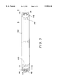
- FIG. 3 shows a top view of the ring binder shown in FIG. 1 with rings removed;
- FIG. 4 shows a sectional view along the line A--A of the ring binder shown in FIG. 3;
- FIG. 5 shows a partial bottom perspective view of the upper structure of the ring binder shown in FIG. 1;
- FIG. 6 shows a sectional view along the line B--B of the ring binder shown in FIG. 3 with rings and as secured to a cover;
- FIG. 7 shows a top perspective view of a second embodiment of a ring binder according to the present invention.
- FIG. 8 shows a bottom perspective view of the ring binder shown in FIG. 7;
- FIG. 9 shows a top view of the ring binder shown in FIG. 7;
- FIG. 10 shows a partial bottom perspective view of the upper structure of the ring binder shown in FIG. 7;
- FIG. 11 shows a sectional view along the line C--C of the ring binder shown in FIG. 9 with rings and as secured to a cover.
- FIGS. 1 and 2 show a first embodiment of a ring binder according to the present invention generally designated as 100.
- the ring binder 100 includes a substantially rigid upper plate member 102 supporting a pair of lower plates 104a and 104b.
- the lower plates 104a and 104b are pivotally movable relative to each other to enable rings 106 to be selectively opened or closed in the conventional manner.
- At each end of the upper plate member 102 are two sets of claws 108.
- a slanted slope 110 and an outer ridge 112. Both the slanted slope 110 and outer ridge 112 are formed integrally with the upper plate member 102.
- each set of claws 108 are arranged along the periphery of a hole 114.
- the claws 108 are pressed into the cover 116 and splayed out to strengthen the connection between the ring binder 100 and the cover 116.
- the outer edges of the outer ridge 112 abut the cover 116 on both sides. Such an arrangement assists in minimizing any wobbling action that may occur between the ring binder 100 and the cover 116.
- FIGS. 7 and 8 show a second embodiment of a ring binder according to the present invention generally designated as 200.
- the ring binder 200 includes a substantially rigid upper plate member 202 supporting a pair of lower plates 204a and 204b.
- the lower plates 204a and 204b are pivotally movable relative to each other to enable rings 206 to be selectively opened or closed in the conventional manner.
- At each end of the upper plate member 202 are two sets of claws 208.
- each set of claws 208 depend from the periphery of a hole 210 surrounded by an outer ridge 212 on all sides.
- the claws 208 are pressed into the cover 214. This action causes the claws 208 to be splayed out and thereby to enhance the connection between the ring binder 200 and the cover 214.
- the outer edges of the outer ridge 212 abut the cover 214 on both sides.
- the two sets of claws 208 are separated by a wall 216 integrally formed with the upper plate member 202. This wall 216 also assists, in addition to the outer ridges 212, in minimizing any wobbling action that may occur between the ring binder 200 and the cover 214.
Landscapes
- Sheet Holders (AREA)
Abstract
A ring binder (100, 200) adapted to be secured to a cover (116, 214) is disclosed as comprising a substantially rigid upper plate member (102, 202) supporting a pair of lower pivotable plates (104a, 104b, 204a, 204b) to which a plurality of rings (106, 206) are mounted, and the upper plate member (102, 202) comprises two ends and the cover (116, 214) abuts at least part of the upper plate member (102, 202), and said part surrounds the end of the upper plate member (102, 202) by substantially 360°.
Description
This invention relates to a ring binder, and in particular a ring binder adapted to be secured by at least one engagement means to a cover.
Conventionally, a ring binder is securable to a cover by at least one rivet having a head portion for engagement with the cover and a tail portion which is deformable to engage a recess in the upper part of the ring binder.
A disadvantage associated with such an arrangement is that the ring binder may wobble relative to the cover such that the connection(s) therebetween may be loosened.
It is therefore an object of the present invention to provide a ring binder in which the aforesaid shortcoming is mitigated.
According to a first aspect of the present invention, there is provided a ring binder adapted to be secured to a base member, which ring binder comprises a substantially rigid upper structure supporting a pivotable lower structure to which a plurality of ring members are mounted characterized in that the upper structure comprises two ends, each of which includes at least one securing means and wherein the part where the securing means joins the upper structure is substantially surrounded.
According to a second aspect of the present invention, there is provided a ring binder adapted to be secured to a base member, which ring binder comprises a substantially rigid upper structure supporting a pivotable lower structure to which a plurality of ring members are mounted characterized in that at least part of the upper structure on both sides of the longitudinal axis of the ring binder near, at or adjacent the extremities of the upper structure is adapted to abut the base member.
The invention will now be described by way of example with reference to the accompanying drawings, in which:
FIG. 1 shows a top perspective view of a first embodiment of a ring binder according to the present invention;
FIG. 2 shows a bottom perspective view of the ring binder shown in FIG. 1;
FIG. 3 shows a top view of the ring binder shown in FIG. 1 with rings removed;
FIG. 4 shows a sectional view along the line A--A of the ring binder shown in FIG. 3;
FIG. 5 shows a partial bottom perspective view of the upper structure of the ring binder shown in FIG. 1;
FIG. 6 shows a sectional view along the line B--B of the ring binder shown in FIG. 3 with rings and as secured to a cover;
FIG. 7 shows a top perspective view of a second embodiment of a ring binder according to the present invention;
FIG. 8 shows a bottom perspective view of the ring binder shown in FIG. 7;
FIG. 9 shows a top view of the ring binder shown in FIG. 7;
FIG. 10 shows a partial bottom perspective view of the upper structure of the ring binder shown in FIG. 7; and
FIG. 11 shows a sectional view along the line C--C of the ring binder shown in FIG. 9 with rings and as secured to a cover.
FIGS. 1 and 2 show a first embodiment of a ring binder according to the present invention generally designated as 100. The ring binder 100 includes a substantially rigid upper plate member 102 supporting a pair of lower plates 104a and 104b. The lower plates 104a and 104b are pivotally movable relative to each other to enable rings 106 to be selectively opened or closed in the conventional manner. At each end of the upper plate member 102 are two sets of claws 108. Around each pair of sets of claws 108 are a slanted slope 110 and an outer ridge 112. Both the slanted slope 110 and outer ridge 112 are formed integrally with the upper plate member 102.
As shown more clearly in FIGS. 3 to 6, each set of claws 108 are arranged along the periphery of a hole 114. When the ring binder 100 is secured to, e.g, a cardboard cover 116 (see FIG. 6), the claws 108 are pressed into the cover 116 and splayed out to strengthen the connection between the ring binder 100 and the cover 116. As shown clearly in FIG. 6, the outer edges of the outer ridge 112 abut the cover 116 on both sides. Such an arrangement assists in minimizing any wobbling action that may occur between the ring binder 100 and the cover 116.
FIGS. 7 and 8 show a second embodiment of a ring binder according to the present invention generally designated as 200. Similar to the first embodiment described above, the ring binder 200 includes a substantially rigid upper plate member 202 supporting a pair of lower plates 204a and 204b. The lower plates 204a and 204b are pivotally movable relative to each other to enable rings 206 to be selectively opened or closed in the conventional manner. At each end of the upper plate member 202 are two sets of claws 208.
As can be seen more clearly in FIGS. 9 to 11, each set of claws 208 depend from the periphery of a hole 210 surrounded by an outer ridge 212 on all sides. When assembling the ring binder 200 to, e.g., a cardboard cover 214, the claws 208 are pressed into the cover 214. This action causes the claws 208 to be splayed out and thereby to enhance the connection between the ring binder 200 and the cover 214. As in the case of the first embodiment discussed above, the outer edges of the outer ridge 212 abut the cover 214 on both sides. In addition, the two sets of claws 208 are separated by a wall 216 integrally formed with the upper plate member 202. This wall 216 also assists, in addition to the outer ridges 212, in minimizing any wobbling action that may occur between the ring binder 200 and the cover 214.
It should be understood that the above only illustrates by way of examples embodiments in which the present invention may be carried out. Further modifications and/or improvements may be made without departing from the spirit of the invention.
Claims (25)
1. A ring binder adapted to be secured to a base member, which ring binder comprises:
a substantially rigid upper structure supporting a pivotable lower structure to which a plurality of ring members are mounted,
the upper structure having two ends, each of which includes
a lowered portion and
an elevated portion which surrounds said lowered portion, and
at least one securing means forming a connection between the base member and each respective end, said connection being situated in said lowered portion.
2. A ring binder according to claim 1 wherein said elevated portion forms a a ridge member.
3. A ring binder according to claim 1 wherein the upper structure is adapted adjacent its ends to abut the base member.
4. A ring binder according to claim 2 wherein the upper structure is adapted adjacent its ends to abut the base member.
5. A ring binder according to claim 1 wherein at least part of laterally extending portions of the upper structure near the ends of the upper structure is adapted to abut the base member.
6. A ring binder according to claim 1 wherein the ring binder comprises two securing means at each respective end.
7. A ring binder adapted to be secured to a base member, which ring binder comprises:
a substantially rigid upper structure supporting a pivotable lower structure to which a plurality of ring members are mounted,
the upper structure having two ends, each of which includes
a lowered portion and
an elevated portion which surrounds said lowered portion, and
two securing means forming connections between the base member and each respective end, said connections being situated in said lowered portion and separated by a raised member.
8. A ring binder according to claim 7 wherein the upper structure further comprises at least one abutting means adapted to abut the base member.
9. A ring binder according to claim 8 wherein the abutting means further comprises at least part of the upper structure of the ring binder near said ends of the upper structure.
10. A ring binder according to claim 8 wherein the ring binder further comprises an intermediate surface between the securing means and the abutting means.
11. A ring binder according to claim 10 wherein the intermediate surface is substantially horizontal.
12. A ring binder according to claim 7 wherein the securing means is integrally formed with the upper structure.
13. A ring binder according to claim 7 wherein the securing means further comprises a plurality of engagement members integrally formed with the upper structure.
14. A ring binder adapted to be secured to a base member, the ring binder comprising
a substantially rigid upper structure supporting a pivotable lower structure to which a plurality of ring members are mounted, the upper structure having two ends, each of which includes
a lowered portion
and an elevated portion which surrounds said lowered portion, and
at least one securing means forming a connection between the base member and each respective end, said connection being situated in said lowered portion, wherein said securing means is integrally formed with the upper structure, and has a plurality of engagement members integrally formed with the upper structure, the engagement members having pointed elements pointing downward from the upper structure.
15. A ring binder according to claim 14 wherein the pointed elements depend downward from and are provided along the periphery of an aperture on the upper structure.
16. A ring binder according to claim 15 wherein the engagement members point away from the central axis of the aperture.
17. A ring binder adapted to be secured to a base member, the ring binder comprising
a substantially rigid upper structure, having end portions and supporting a pivotable lower structure to which a plurality of ring members are mounted, whereby said end portions have outer edges which are directed downwards and whereby portions of said outer edges are abutting means adapted to abut the base member, the ring binder having two securing means adjacent to either end thereof, wherein the two securing means are separated by a raised member.
18. A ring binder according to claim 17 wherein the ring binder further comprises an intermediate surface between the securing means and the abutting means.
19. A ring binder according to claim 18 wherein the intermediate surface is substantially horizontal.
20. A ring binder according to claim 17 wherein the securing means further comprise a plurality of engagement members integrally formed with the upper structure.
21. A ring binder adapted to be secured to a base member, the ring binder comprising
a substantially rigid upper structure supporting a pivotable lower structure to which a plurality of ring members are mounted, said upper structure having two ends, each of which includes an outer edge which is directed downwards, whereby laterally extending portions of said outer edges is adapted to abut the base member, the ring binder having at least one securing means adjacent to each of said ends, the securing means having a plurality of engagement members integrally formed with the upper structure, the engagement members having pointed elements pointing downward from the upper structure.
22. A ring binder according to claim 21 wherein the pointed elements depend downward from and are provided along the periphery of an aperture of the upper structure.
23. A ring binder according to claim 22 wherein the pointed elements point away from the central axis of the aperture.
24. A ring binder adapted to be secured to a base member, said ring binder comprising
a substantially rigid upper structure supporting a pivotable lower structure to which a plurality of ring members are mounted,
the upper structure having two ends, each of which includes
a lowered portion and
an elevated portion which surrounds said lowered portion, and
said elevated portions having outer edges which are directed downward,
whereby laterally extending portions of said outer edges abut the base member on both of said ends of the ring binder.
25. A ring binder adapted to be secured to a base member, said ring binder comprising
a substantially rigid upper structure supporting a pivotable lower structure to which a plurality of ring members are mounted,
said upper structure including two end portions,
said end portions respectively having outer edges which are directed downward,
wherein the outer edges at the sides and the ends of the end portions, form a continuous abutment with the base member.
Priority Applications (1)
| Application Number | Priority Date | Filing Date | Title |
|---|---|---|---|
| US08/546,021 US5980146A (en) | 1995-10-20 | 1995-10-20 | Ring binder |
Applications Claiming Priority (1)
| Application Number | Priority Date | Filing Date | Title |
|---|---|---|---|
| US08/546,021 US5980146A (en) | 1995-10-20 | 1995-10-20 | Ring binder |
Publications (1)
| Publication Number | Publication Date |
|---|---|
| US5980146A true US5980146A (en) | 1999-11-09 |
Family
ID=24178534
Family Applications (1)
| Application Number | Title | Priority Date | Filing Date |
|---|---|---|---|
| US08/546,021 Expired - Fee Related US5980146A (en) | 1995-10-20 | 1995-10-20 | Ring binder |
Country Status (1)
| Country | Link |
|---|---|
| US (1) | US5980146A (en) |
Cited By (9)
| Publication number | Priority date | Publication date | Assignee | Title |
|---|---|---|---|---|
| USD453026S1 (en) | 2001-08-03 | 2002-01-22 | World Wide Stationery Manufacturing Company, Ltd. | Ring binder |
| USD457559S1 (en) | 2001-08-03 | 2002-05-21 | World Wide Stationery Manufacturing Company, Ltd. | Ring binder |
| US6394686B1 (en) | 2001-01-13 | 2002-05-28 | U.S. Ring Binder Lp | Clinch fastener |
| US6758621B2 (en) | 2001-08-03 | 2004-07-06 | World Wide Stationery Manufacturing Company, Ltd. | Ring binder mechanism |
| US7399136B2 (en) | 2006-01-06 | 2008-07-15 | Staples The Office Superstore Llc | Molded binder |
| US7524127B2 (en) | 2005-12-12 | 2009-04-28 | Staples The Office Superstore, Llc | Ring binder mechanism |
| US7527449B2 (en) | 2005-12-12 | 2009-05-05 | Staples The Office Superstore, Llc | Ring binder mechanism |
| USD616023S1 (en) | 2006-07-06 | 2010-05-18 | World Wide Stationery Mfg. Co., Ltd. | Push button ring mechanism having rectilinear binder rings |
| US20110299914A1 (en) * | 2010-06-02 | 2011-12-08 | Chun Yuen To | Ring binder mechanism |
Citations (12)
| Publication number | Priority date | Publication date | Assignee | Title |
|---|---|---|---|---|
| US813753A (en) * | 1905-05-24 | 1906-02-27 | Sieber & Trussell Mnfg Co | Loose-leaf binder. |
| US1494626A (en) * | 1921-09-19 | 1924-05-20 | Irving Pitt Mfg Company | Loose-leaf book |
| US1813599A (en) * | 1929-05-22 | 1931-07-07 | Henry T Adams | Loose leaf ring book |
| US1816021A (en) * | 1929-01-25 | 1931-07-28 | Meyerson Max | Temporary binder |
| US1932874A (en) * | 1932-05-27 | 1933-10-31 | Adams | Ring binder |
| US2325155A (en) * | 1941-05-16 | 1943-07-27 | Wilson Jones Co | Loose-leaf binder |
| US2447963A (en) * | 1944-02-21 | 1948-08-24 | Wilson Jones Co | Loose-leaf binder |
| US2552076A (en) * | 1948-12-29 | 1951-05-08 | Wilson Jones Co | Loose-leaf binder |
| EP0188679A2 (en) * | 1985-01-24 | 1986-07-30 | Robert Krause GmbH & Co. KG | Ring mechanism |
| CA1211335A (en) * | 1983-02-10 | 1986-09-16 | Lewis Cohen | Ring mechanism for loose leaf binder |
| GB2209500A (en) * | 1987-09-08 | 1989-05-17 | Lewis Cohen | Ring binder mechanism |
| US5476335A (en) * | 1995-03-31 | 1995-12-19 | U.S. Ring Binder Corp. | Locking mechanism for a ring binder |
-
1995
- 1995-10-20 US US08/546,021 patent/US5980146A/en not_active Expired - Fee Related
Patent Citations (12)
| Publication number | Priority date | Publication date | Assignee | Title |
|---|---|---|---|---|
| US813753A (en) * | 1905-05-24 | 1906-02-27 | Sieber & Trussell Mnfg Co | Loose-leaf binder. |
| US1494626A (en) * | 1921-09-19 | 1924-05-20 | Irving Pitt Mfg Company | Loose-leaf book |
| US1816021A (en) * | 1929-01-25 | 1931-07-28 | Meyerson Max | Temporary binder |
| US1813599A (en) * | 1929-05-22 | 1931-07-07 | Henry T Adams | Loose leaf ring book |
| US1932874A (en) * | 1932-05-27 | 1933-10-31 | Adams | Ring binder |
| US2325155A (en) * | 1941-05-16 | 1943-07-27 | Wilson Jones Co | Loose-leaf binder |
| US2447963A (en) * | 1944-02-21 | 1948-08-24 | Wilson Jones Co | Loose-leaf binder |
| US2552076A (en) * | 1948-12-29 | 1951-05-08 | Wilson Jones Co | Loose-leaf binder |
| CA1211335A (en) * | 1983-02-10 | 1986-09-16 | Lewis Cohen | Ring mechanism for loose leaf binder |
| EP0188679A2 (en) * | 1985-01-24 | 1986-07-30 | Robert Krause GmbH & Co. KG | Ring mechanism |
| GB2209500A (en) * | 1987-09-08 | 1989-05-17 | Lewis Cohen | Ring binder mechanism |
| US5476335A (en) * | 1995-03-31 | 1995-12-19 | U.S. Ring Binder Corp. | Locking mechanism for a ring binder |
Cited By (12)
| Publication number | Priority date | Publication date | Assignee | Title |
|---|---|---|---|---|
| US6394686B1 (en) | 2001-01-13 | 2002-05-28 | U.S. Ring Binder Lp | Clinch fastener |
| USD453026S1 (en) | 2001-08-03 | 2002-01-22 | World Wide Stationery Manufacturing Company, Ltd. | Ring binder |
| USD457559S1 (en) | 2001-08-03 | 2002-05-21 | World Wide Stationery Manufacturing Company, Ltd. | Ring binder |
| US6758621B2 (en) | 2001-08-03 | 2004-07-06 | World Wide Stationery Manufacturing Company, Ltd. | Ring binder mechanism |
| US7524127B2 (en) | 2005-12-12 | 2009-04-28 | Staples The Office Superstore, Llc | Ring binder mechanism |
| US7527449B2 (en) | 2005-12-12 | 2009-05-05 | Staples The Office Superstore, Llc | Ring binder mechanism |
| US7399136B2 (en) | 2006-01-06 | 2008-07-15 | Staples The Office Superstore Llc | Molded binder |
| USD616934S1 (en) | 2006-06-07 | 2010-06-01 | World Wide Stationery Mfg. Co., Ltd. | Single lever ring mechanism having rectilinear binder rings |
| USD622316S1 (en) | 2006-06-07 | 2010-08-24 | World Wide Stationery Mfg. Co., Ltd. | Dual lever ring mechanism with rectilinear binder rings |
| USD616023S1 (en) | 2006-07-06 | 2010-05-18 | World Wide Stationery Mfg. Co., Ltd. | Push button ring mechanism having rectilinear binder rings |
| USRE41852E1 (en) | 2006-07-06 | 2010-10-26 | World Wide Stationery Mfg. Co., Ltd. | Rectilinear binder ring |
| US20110299914A1 (en) * | 2010-06-02 | 2011-12-08 | Chun Yuen To | Ring binder mechanism |
Similar Documents
| Publication | Publication Date | Title |
|---|---|---|
| EP0764549A1 (en) | A ring binder | |
| US6168339B1 (en) | Ring binder | |
| USD951732S1 (en) | Annular blade for a low friction rotary knife | |
| US5980146A (en) | Ring binder | |
| US5577852A (en) | Ring binder mechanism | |
| US6339908B1 (en) | Wood floor board assembly | |
| US6033144A (en) | Ring binder mechanism | |
| CA2405776A1 (en) | Drop box container | |
| WO1997021011B1 (en) | Portable floor | |
| GB2144987A (en) | Improvements in or relating to wall plaques | |
| USD1055322S1 (en) | Roof tile | |
| CA2170001A1 (en) | Ring binder | |
| USD408851S (en) | Ring binder | |
| US6223390B1 (en) | Carpet sample board handle | |
| USD389183S (en) | Ring binder | |
| HK1011330A (en) | A ring binder | |
| USD405825S (en) | Embossed and decorated spine panel and cover for ring binder | |
| EP1203670A2 (en) | A ring binder mechanism | |
| EP0765768A1 (en) | A ring binder | |
| US6371570B1 (en) | Securing member for a steel ring of a wheel cover | |
| US20020118404A1 (en) | Scanner capable of adjusting the height of a paper cover | |
| USD401816S (en) | Pumpkin scoop | |
| US6526626B1 (en) | Carpet sample board spacers | |
| CN1148551A (en) | ring binder | |
| JP3418857B2 (en) | Upper support device for partition panel |
Legal Events
| Date | Code | Title | Description |
|---|---|---|---|
| AS | Assignment |
Owner name: WORLD WIDE STATIONERY MANUFACTURING CO. LTD. KOON Free format text: ASSIGNMENT OF ASSIGNORS INTEREST;ASSIGNOR:YUEN, SIMON CHUEN;REEL/FRAME:007832/0293 Effective date: 19960119 |
|
| REMI | Maintenance fee reminder mailed | ||
| LAPS | Lapse for failure to pay maintenance fees | ||
| STCH | Information on status: patent discontinuation |
Free format text: PATENT EXPIRED DUE TO NONPAYMENT OF MAINTENANCE FEES UNDER 37 CFR 1.362 |
|
| FP | Lapsed due to failure to pay maintenance fee |
Effective date: 20031109 |