US5961345A - Faceplate system - Google Patents
Faceplate system Download PDFInfo
- Publication number
- US5961345A US5961345A US09/006,848 US684898A US5961345A US 5961345 A US5961345 A US 5961345A US 684898 A US684898 A US 684898A US 5961345 A US5961345 A US 5961345A
- Authority
- US
- United States
- Prior art keywords
- faceplate
- plate
- insert
- legs
- mounting
- Prior art date
- Legal status (The legal status is an assumption and is not a legal conclusion. Google has not performed a legal analysis and makes no representation as to the accuracy of the status listed.)
- Expired - Lifetime
Links
- 125000006850 spacer group Chemical group 0.000 claims abstract description 23
- 238000013459 approach Methods 0.000 description 8
- 239000000835 fiber Substances 0.000 description 4
- 230000009977 dual effect Effects 0.000 description 3
- 238000000034 method Methods 0.000 description 1
- 238000012986 modification Methods 0.000 description 1
- 230000004048 modification Effects 0.000 description 1
- 239000013307 optical fiber Substances 0.000 description 1
Images


Classifications
-
- H—ELECTRICITY
- H01—ELECTRIC ELEMENTS
- H01R—ELECTRICALLY-CONDUCTIVE CONNECTIONS; STRUCTURAL ASSOCIATIONS OF A PLURALITY OF MUTUALLY-INSULATED ELECTRICAL CONNECTING ELEMENTS; COUPLING DEVICES; CURRENT COLLECTORS
- H01R13/00—Details of coupling devices of the kinds covered by groups H01R12/70 or H01R24/00 - H01R33/00
- H01R13/46—Bases; Cases
- H01R13/516—Means for holding or embracing insulating body, e.g. casing, hoods
- H01R13/518—Means for holding or embracing insulating body, e.g. casing, hoods for holding or embracing several coupling parts, e.g. frames
-
- H—ELECTRICITY
- H01—ELECTRIC ELEMENTS
- H01R—ELECTRICALLY-CONDUCTIVE CONNECTIONS; STRUCTURAL ASSOCIATIONS OF A PLURALITY OF MUTUALLY-INSULATED ELECTRICAL CONNECTING ELEMENTS; COUPLING DEVICES; CURRENT COLLECTORS
- H01R13/00—Details of coupling devices of the kinds covered by groups H01R12/70 or H01R24/00 - H01R33/00
- H01R13/73—Means for mounting coupling parts to apparatus or structures, e.g. to a wall
- H01R13/74—Means for mounting coupling parts in openings of a panel
- H01R13/741—Means for mounting coupling parts in openings of a panel using snap fastening means
- H01R13/743—Means for mounting coupling parts in openings of a panel using snap fastening means integral with the housing
-
- H—ELECTRICITY
- H02—GENERATION; CONVERSION OR DISTRIBUTION OF ELECTRIC POWER
- H02G—INSTALLATION OF ELECTRIC CABLES OR LINES, OR OF COMBINED OPTICAL AND ELECTRIC CABLES OR LINES
- H02G3/00—Installations of electric cables or lines or protective tubing therefor in or on buildings, equivalent structures or vehicles
- H02G3/02—Details
- H02G3/08—Distribution boxes; Connection or junction boxes
- H02G3/14—Fastening of cover or lid to box
Definitions
- the invention relates to a faceplate system and more particularly to an improved faceplate system that employs removably mounted inserts.
- Faceplates are used to support a variety of electrical components. Some of the conventional electrical components supported by faceplates are telephone plugs, electrical connectors, light switches, and electrical switches. Moreover, faceplates find use in more complex interconnects, such as complex office interconnect systems using computers. These complex systems include a variety of interconnects at many locations that are typically supported by faceplates. And various faceplate configurations are required to support the electrical elements in different configurations.
- AXESSTM receptacle housing faceplate products AXESSTM receptacle housing faceplate products.
- Another approach uses snap-in tabs on inserts or on the connectors themselves.
- An example of such an approach is the MOD-TAPTM Universal System Outlet wall plate system.
- Yet another approach uses tabs on the faceplate.
- An example of such an approach is MOD-COMTM Executive Series faceplates.
- the snap-in approaches require (for insert or module removal) small unsightly visible openings in the face of the faceplate between inserts or modules. And removable of the snap-in inserts or modules requires a tool to be inserted in the openings to pry a insert or module for removal. Then too, a snap-in can be inadvertently pushed or pulled out. Pulling out a snap-in member can occur with front access faceplates by pulling a cable too hard; pushing out a snap-in member can occur with rear access faceplates by pushing a cable too hard.
- An object of the invention is an improved faceplate that interchanges inserts or modules with different types of media connectors.
- Another object of the invention is a faceplate that provides a stable mounting for inserts on a faceplate frame and that provides easy mounting of inserts.
- Yet another object of the invention is a configurable faceplate having an improved appearance.
- a faceplate according to the invention includes a faceplate frame.
- the frame includes a pair of opposed spaced apart parallel elongated side portions and a pair of opposed spaced apart parallel elongated end portions extending between the elongated side portions in a direction normal thereto.
- Each of the elongated side and end portions have a front, back, and inner surfaces. The front and inner surfaces intersect normal to each other with each of the inner surfaces extending from its intersection with its respective front surface in a direction toward the back surface of the faceplate.
- each of the end regions of one of the elongated end portions are joined to an end region of one of the elongated side portions, and each of the end regions of the other of the elongated end portions are joined to the opposite end region of one of the elongated side portions.
- the inner surfaces of the elongated side and end portions defines a rectangular opening therebetween.
- the faceplate frame further includes a mounting rail on each of the inner surfaces of the elongated side portions intermediate the front and back surfaces.
- Each of the mounting rails has a front surface facing the front of the faceplate and a back surface facing the back of the faceplate. Further, the rails are shaped to include a spaced apart pair of notches therethrough providing access to the back surface of its respective mounting rail.
- the faceplate further includes a mounting insert or module removably mounted on the faceplate frame in the rectangular opening.
- the insert includes a rectangular plate extending across the width of the rectangular opening of the faceplate frame.
- the plate itself has an opening therethrough for accepting a media connector and has a front surface in coplanar relationship with the front surfaces of the elongated side and end portions.
- the mounting insert further includes a leg at each of the corner regions of the plate and a spacer wall at each end of the plate between the legs. Each of such spacer walls has its outer surface flush with its end edge surface of the plate and extends away from the plate in a direction normal thereto to terminate in sliding engagement with the front surface of its associated mounting rail.
- Each of the legs is located on the underside of the plate with its outwardly facing surface in the same plane as the rear side of its associated spacer wall and includes a ledge surface at its free end region extending from its outwardly facing surface to be in sliding engagement with the back surface of its associated mounting rail.
- the pair of notches in the mounting rails are spaced apart the same distance as the distance between the pair of legs at each end of the plate.
- the ledge surfaces of the legs are dimensioned to allow movement of the ledge surfaces through the notches and into sliding engagement with the back surface of the rails during mounting of the plate on the faceplate frame.
- a stop surface on the faceplate frame is in abutting relationship with one lengthwise edge of the plate with: each of the legs of the plate being in adjacent relationship to and on one side of its respective notch; and the ledge surface of the legs and the spacer walls being in sliding engagement with the front and back rail surfaces respectfully.
- a bezel stop is removably mounted on the faceplate in abutting relationship with the other lengthwise edge of the plate in a location to stop to keep the insert in fixed mounted position on the faceplate frame.
- the invention allows easy mounting and removal of a faceplate insert or module from a faceplate frame.
- One merely moves an insert into the faceplate opening to move the legs of the insert into the mounting rail notches and brings the spacer walls into sliding engagement with the front surfaces of the mounting walls.
- the insert is then moved on the mounting rails to bring the ledge surfaces of the insert legs to one side of the notches into sliding engagement with the back surfaces of the mounting rails and to bring the insert into abutting relationship with a stop surface.
- the stop surface is positioned to keep the insert captured on the mounting rails between the ledge surfaces of the legs and engaging surfaces of the spacer walls with the ledge surfaces to one side of their respective mounting rail notches.
- the position of the insert is fixed by mounting a locking bezel into abutting relationship with the insert.
- FIG. 1 is a front perspective view of a configurable faceplate according to the principles of the invention that includes three connector mounting inserts. One of the inserts is shown as a blank.
- FIG. 2 is a partially exploded front perspective view of the faceplate of FIG. 1.
- the faceplate is shown with the uppermost insert and with a snap-in locking bezel separated from its mounted location on the faceplate frame.
- a snap-in lower cover is also shown separated from its mounted location on the faceplate frame.
- FIG. 3 is a partially exploded rear perspective view of the faceplate of FIG. 1. As with FIG. 2, the uppermost insert, locking bezel, and lower cover are shown separated from their mounted locations on the faceplate frame.
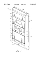
- FIG. 4 is a rear elevation view of the faceplate of FIG. 1. All the inserts, the locking bezel and the lower cover are shown mounted on the faceplate frame.
- FIG. 5 is a front perspective view of an alternative embodiment of a faceplate according to the principles of the invention.
- the faceplate illustrated in FIG. 5 is a dual faceplate.
- FIGS. 1-4 illustrate a rectangular faceplate 10 according to the principles of the invention.
- the faceplate 10 includes a faceplate frame 14, inserts or modules 16, 18, and 20, a snap-in locking bezel 24, and a snap-in cover 26.
- the faceplate frame 14 is conveniently rigid plastic and is shaped like a picture frame.
- the frame 14 includes opposed spaced apart parallel elongated side portions 30 and 32 and opposed spaced apart parallel elongated end portions 34 and 36 extending between the side portions 30 and 32.
- the end portions 34 and 36 are in perpendicular relationship with the side portions 30 and 32.
- the side portions 30 and 32 include front surfaces 40 and 41, back surfaces 42 and 43, and inner surfaces 44 and 45 respectfully.
- the end portions 34 and 36 include front surfaces 46 and 47, back surfaces 48 and 49 ,and inner surfaces 50 and 51 respectfully.
- the inner surfaces 44, 45, 50, and 51 extend from their intersection with their respective front surfaces40, 41, 46, and 47 toward the back surfaces 42, 43, 48, and 49 to define a rectangular opening 54.
- the opening 54 is shown partially unfilled in FIGS. 2 and 3 as a result of the explode position of insert 16 in FIGS. 2 and 3.
- the faceplate frame 14 further includes a mounting rail 56 on each of the inner walls 44 and 45 of the elongated sidewall portions 30 and 32.
- the mounting rails 56 are spaced in recessed relationship with the front surfaces 40, 41, 46, and 47.
- the mounting rails 56 have pairs of spaced a access notches 58. As shown in the figures, each of the rails 56 has three pairs of notches 58--one pair on each of the rails 56 for each of the inserts 16, 18, and 20.
- the faceplate 10 is illustrated with three inserts 16, 18, and 20 removably mounted on the frame 14 in the rectangular opening 54. But a faceplate according to the invention can be constructed with dimensions to use more or less than three inserts. As illustrated, the front surfaces of the inserts 16, 18, and 20 are coplanar with the front surfaces 40 and 41 of the faceplate 10.
- each of the inserts 16, 18, and 20 is identical except its media connector opening configuration.
- the topmost insert 16 has a connector opening 66 configured to accept an SC optical fiber connector.
- the middle insert 18 has two identical openings 68 configured to accept standard keystone connectors.
- the bottom insert 20 is blank. And, of course, other connector openings are contemplated and used for other types of connectors, for exampleco-axial, twisted pair, and the like.
- Each of the inserts includes a rectangular plate 70 that extends across the width of the rectangular opening 54.
- the inserts are identical except for their media connector openings (i.e., openings 66 and 68) or lack thereof.
- insert 16 includes a plate 70a; insert 18, plate 70b; and insert 20, plate 70c. Plate 70c is blank.
- Each of the inserts 16, 18, and 20 includes four legs 74, one leg at each of the corner regions of its respective plate 70.
- each of the legs 70 is identical.
- Insert 16 is shown with legs 74a; insert 18, with legs 74b; and insert 20, with legs 74c.
- the endwise distance between the legs 70 is the same as the distance between pairs of notches 58 on the rails 56.
- Each of the legs has a ledge surface 76 facing toward the underside of its respective plate 70, as shown in the FIGS.
- the ledges 76 are of such a size and position to engage the back surface of their respective mounting rail 56 in sliding relationship when the inserts are in mounted position on the faceplate frame 14. As shown more clearly in the FIGS. 3 and 4, the ledge surfaces 76 are located to one side of the notches 58 in the mounting rails 56 and are in sliding engagement therewith.
- each of the inserts 16, 18, and 20 includes a spacer wall 78 located at each end of the each of the plates 70 between the legs 74.
- the spacer walls 78 are shown extending at right angles from the their respective plates 70 on the same side thereof as the legs 74.
- Insert 16 is shown with spacer walls 78a; insert 18, with spacer wall 78b; and insert 20, with spacer walls 78c.
- Each of the outwardly facing surfaces of the walls 78 is flush or coextensive with the end edge surface of its respective plate 70.
- the ledge surfaces 76 are shown to extend to terminate in a plane coextensive with the outer surfaces of the spacer walls 78.
- the distance between the free ends of the spacer walls 78 and the ledge surfaces 76 is the thickness of the rails 56. Consequently, the ledge surfaces 76 and the end surfaces of the spacer walls 78 slidingly engage the back surfaces and front surfaces respectively of the mounting rails 56 when an insert is in mounted position on the rails 56. The insert is, therefore, secure on the mounting rails 56.
- the inserts 16, 18, and 20 are in abutting relationship with each other along their lengthwise edges when they are in mounted position on the faceplate frame 14.
- the lowermost insert 20 insert is in lengthwise butting relationship with the inner surface of the lower end portion 36. Therefore, the inner surface of the lower portion 36 acts as a stop surface.
- the upper lengthwise edges (as viewed in the FIGURES) of inserts 18 and 20 also function as stop surfaces for insert 16 and 18 respectively.
- a person merely needs to move an insert into the rectangular opening 54 of the frame 14 and position its legs 74 into notches 58 of the mounting rails 56. With both the ledge surfaces 76 and the spacer walls 78 aligned for slide fit relationship on opposite sides of the rails 56, the insert is moved downwardly (as viewed in the figures) to place the lower edge of the insert in butting relationship with a stop surface and the legs 74 to one side of their respective notches 58. The process is repeated for the next insert. Mounting is completed by snapping the locking bezel 24 in place.
- the faceplate 10 can be fasted to a wall by screws or the like (not shown) using fastening openings 82 and 84 on the frame 14. And as can be seen more clearly in the FIG. 1, the locking bezel 24 covers the fastening opening 82 when mounted. The cover 26 covers the fastening opening 84 when mounted.
- the locking bezel 24 includes tabs 90 at one lengthwise side, an outwardly facing ledge 92 at the other lengthwise side, inwardly facing spacer legs 94 at the other lengthwise side, and detentes 96.
- the frame 14 includes openings 98 and detente recesses 100 (see FIG. 2) on the inner surfaces 44 and 45.
- the locking bezel 24 is mounted in position on the frame 14 by placing the tabs 90 in the openings 98 and moving the lower portion of the bezel 24 to bring the detentes 96 into snap-in relationship with the detente recesses 100. In such position the spacer legs engage the upper or font surfaces of the mounting rails 56 in abutting relationship.
- the ledge 92 is used in removal of the bezel 24 from the frame 14.
- the cover 26 includes tabs 104 at its lower side (as viewed in FIGS. 2 and 3), an outwardly facing ledge 106, detentes 108 at the ends of the cover 26.
- the frame 14 includes a recess 109, detente recesses 110, and mounting openings 112.
- the cover 26 is mounted by placing the tabs 104 in the openings 112 and moving the detentes 108 into snap-in relationship with the detente recesses 110. When mounted, the cover 26 rests on the floor of the recess 109. And, as illustrated, the outwardly facing surface of the cover 26 is flush with the other front surfaces of the frame 14.
- FIG. 5 shows an alternative faceplate according to the principles of the invention. Illustrated is a dual faceplate 10'. As shown, the left side of faceplate 10' is the same is the faceplate 10, except for the middle insert 18'.
- the faceplate 10 shown in FIGS. 1-4 includes a middle insert 18 that has two keystone connector openings 68.
- the faceplate 10' includes a middle insert 18' that has two connector openings for ST fiber optic connectors.
- FIG. 5 shows anST fiber optic connector 116 (without its cap) mounted in each of the connector openings of insert 18'.
- the opening 66 in insert 16 is shown in FIG. 5 with an SC fiber optic connector 118 mounted therein.
- the right side of the dual faceplate 10' includes an insert 120 that holds patch panels 122 and 126.
- the insert 120 which is shown configured like a picture frame, is mounted on the faceplate frame 14' in the same manner as discussed in connection with the mounting of the inserts 16, 18, and 20 on the faceplate frame 14.
- the patch panels 122 and 126 are snapped-in the opening of the insert 120 in a conventional manner.
- the patch panel 122 is shown with data connectors 124 mounted in its two connector openings.
- the patch panel 126 is shown with ST fiber optic connectors 128 (with their covers) mounted in a conventional manner in its two connector openings.
Landscapes
- Connector Housings Or Holding Contact Members (AREA)
Abstract
Description
Claims (1)
Priority Applications (1)
| Application Number | Priority Date | Filing Date | Title |
|---|---|---|---|
| US09/006,848 US5961345A (en) | 1998-01-14 | 1998-01-14 | Faceplate system |
Applications Claiming Priority (1)
| Application Number | Priority Date | Filing Date | Title |
|---|---|---|---|
| US09/006,848 US5961345A (en) | 1998-01-14 | 1998-01-14 | Faceplate system |
Publications (1)
| Publication Number | Publication Date |
|---|---|
| US5961345A true US5961345A (en) | 1999-10-05 |
Family
ID=21722919
Family Applications (1)
| Application Number | Title | Priority Date | Filing Date |
|---|---|---|---|
| US09/006,848 Expired - Lifetime US5961345A (en) | 1998-01-14 | 1998-01-14 | Faceplate system |
Country Status (1)
| Country | Link |
|---|---|
| US (1) | US5961345A (en) |
Cited By (49)
| Publication number | Priority date | Publication date | Assignee | Title |
|---|---|---|---|---|
| US6050849A (en) * | 1998-06-29 | 2000-04-18 | Compal Electronics, Inc. | Stand having a housing adapted for supporting a liquid crystal display panel on a base, and a universal serial bus hub module mounted detachably on the housing |
| USD449217S1 (en) | 2000-06-30 | 2001-10-16 | Adc Telecommunications, Inc. | Designation window |
| USD449584S1 (en) | 2000-04-10 | 2001-10-23 | Thomas & Betts International, Inc. | Wall plate for directional couplers |
| US6422898B1 (en) * | 2000-08-31 | 2002-07-23 | Corning Cable Systems Llc | Retaining hook assembly for outlet cover |
| US6421941B1 (en) | 2000-06-30 | 2002-07-23 | Adc Telecommunications, Inc. | Designation window |
| US6616005B1 (en) * | 2000-08-28 | 2003-09-09 | Hubbell Incorporated | Modular faceplate assembly for an electrical box |
| US6793524B2 (en) | 2001-03-30 | 2004-09-21 | Adc Telecommunications, Inc. | Multimedia outlet with protective cover |
| US20050194176A1 (en) * | 2004-02-25 | 2005-09-08 | Control4 Corporation | Faceplate attachment system |
| WO2006034972A1 (en) * | 2004-09-30 | 2006-04-06 | Siemens Aktiengesellschaft | Mounting frame for mounting installation modules and corresponding method |
| USD532288S1 (en) * | 2005-08-19 | 2006-11-21 | Leviton Manufacturing Co., Inc. | Two port wall plate insert |
| WO2006125033A1 (en) * | 2005-05-18 | 2006-11-23 | 3M Innovative Properties Company | Frame assembly |
| US20060264090A1 (en) * | 2005-05-18 | 2006-11-23 | Dower William V | Electrical connector assembly and method of forming the same |
| USD532678S1 (en) * | 2005-08-19 | 2006-11-28 | Leviton Manufacturing Co., Inc. | Three port wall plate insert |
| US20070037442A1 (en) * | 2005-08-12 | 2007-02-15 | Lastar, Inc. | Integrated wall plate assembly and premise wiring system incorporating the same |
| US7187695B2 (en) | 1998-07-28 | 2007-03-06 | Serconet Ltd. | Local area network of serial intelligent cells |
| US20070051528A1 (en) * | 2005-02-25 | 2007-03-08 | Bangert Brian D | Novel decorative cover plates |
| USD539119S1 (en) * | 2005-08-19 | 2007-03-27 | Leviton Manufacturing Co., Inc. | Four port wall plate insert |
| USD539118S1 (en) * | 2005-08-19 | 2007-03-27 | Leviton Manufacturing Co., Inc. | Six port wall plate insert |
| US20070167128A1 (en) * | 2006-01-17 | 2007-07-19 | Popowitz Jeffrey P | Ventilation register system |
| US20080002937A1 (en) * | 2006-06-29 | 2008-01-03 | Gordon Spisany | Patch panels with communications connectors that are rotatable about a vertical axis |
| US20080035364A1 (en) * | 2006-01-31 | 2008-02-14 | Panduit Corp. | Stainless Steel Faceplates with Labels |
| US20080138573A1 (en) * | 2002-03-21 | 2008-06-12 | Panduit Corp. | Apparatus and System for Identification Labeling |
| US7483524B2 (en) | 1999-07-20 | 2009-01-27 | Serconet, Ltd | Network for telephony and data communication |
| US20090221179A1 (en) * | 2008-02-28 | 2009-09-03 | Arnel Berton Citurs | Tamper resistant faceplate system |
| US7586040B1 (en) * | 2005-10-11 | 2009-09-08 | Pass & Seymour, Inc. | Multiple component wall plate |
| US20090247006A1 (en) * | 2008-01-22 | 2009-10-01 | Wi3, Inc., New York | Network access point having interchangeable cartridges |
| US20100051312A1 (en) * | 2008-09-04 | 2010-03-04 | James Daniels | Modular electrical wall cover system |
| US7683257B1 (en) * | 2005-08-23 | 2010-03-23 | Taymac Corporation | Electrical cover plate |
| US7686653B2 (en) | 2003-09-07 | 2010-03-30 | Mosaid Technologies Incorporated | Modular outlet |
| US7756268B2 (en) | 2004-02-16 | 2010-07-13 | Mosaid Technologies Incorporated | Outlet add-on module |
| US20100296789A1 (en) * | 2009-05-22 | 2010-11-25 | Wade Womack | Telecommunications patching system with cable management system and related cable management equipment |
| US20110192628A1 (en) * | 2010-02-08 | 2011-08-11 | Siemens Industry, Inc. | Breaker tray for a panelboard cover |
| US8072779B1 (en) * | 2009-01-07 | 2011-12-06 | Pass & Seymour, Inc. | Recessed electrical device housing assembly and clip |
| US8242364B1 (en) | 1996-12-30 | 2012-08-14 | Hubbell Incorporated | Electrical cover plate |
| US20120222896A1 (en) * | 2009-01-07 | 2012-09-06 | Pass & Seymour, Inc. | Modular device housing assembly |
| US8299359B2 (en) | 2006-07-18 | 2012-10-30 | Leviton Manufacturing Company, Inc. | Wiring device and cover plate snap-on assembly |
| US8350154B1 (en) | 2005-08-23 | 2013-01-08 | Hubbell Incorporated | Universal wall plate mount |
| US20130277086A1 (en) * | 2012-04-19 | 2013-10-24 | Pass & Seymour, Inc. | Modular electrical wiring device system |
| US8592681B2 (en) | 2010-04-27 | 2013-11-26 | Leviton Manufacturing Co., Inc. | Electrical device with removable cover |
| USD721043S1 (en) * | 2012-11-14 | 2015-01-13 | Eric Tonnesen | Electrical outlet cover |
| USD721336S1 (en) * | 2012-11-14 | 2015-01-20 | Eric Tonnesen | Electrical outlet cover |
| US20170182658A1 (en) * | 2015-12-23 | 2017-06-29 | Comau S.P.A. | Multi-Axis Industrial Robot, In Particular of a SCARA Type |
| USD797545S1 (en) * | 2016-09-22 | 2017-09-19 | Crestron Electronics, Inc. | Wall mounted jack panel |
| USD799934S1 (en) * | 2016-09-22 | 2017-10-17 | Crestron Electronics, Inc. | Wall mounted receptacle |
| EP3293842A1 (en) * | 2016-09-12 | 2018-03-14 | Schneider Electric España, S.A. | Frame for mounting electrical apparatus |
| US10923889B2 (en) | 2017-10-17 | 2021-02-16 | Crestron Electronics, Inc. | Ganging a plurality of wall mounted electric devices |
| US10943749B2 (en) | 2018-03-15 | 2021-03-09 | Crestron Electronics, Inc. | Wall mounted control device with interchangeable buttons |
| US20210159683A1 (en) * | 2019-11-25 | 2021-05-27 | Te Connectivity Corporation | Electrical element pass through plate constructions |
| US11224112B2 (en) | 2018-01-09 | 2022-01-11 | Lutron Technology Company Llc | Device for powering a modular assembly |
Citations (3)
| Publication number | Priority date | Publication date | Assignee | Title |
|---|---|---|---|---|
| US4875880A (en) * | 1988-07-21 | 1989-10-24 | Digital Equipment Corporation | Modular faceplate system |
| US5452175A (en) * | 1994-11-07 | 1995-09-19 | Tsai; Pei-Lien | Construction of a panel |
| US5460541A (en) * | 1992-11-18 | 1995-10-24 | Weatherley; Richard | Jack socket assembly |
-
1998
- 1998-01-14 US US09/006,848 patent/US5961345A/en not_active Expired - Lifetime
Patent Citations (3)
| Publication number | Priority date | Publication date | Assignee | Title |
|---|---|---|---|---|
| US4875880A (en) * | 1988-07-21 | 1989-10-24 | Digital Equipment Corporation | Modular faceplate system |
| US5460541A (en) * | 1992-11-18 | 1995-10-24 | Weatherley; Richard | Jack socket assembly |
| US5452175A (en) * | 1994-11-07 | 1995-09-19 | Tsai; Pei-Lien | Construction of a panel |
Cited By (93)
| Publication number | Priority date | Publication date | Assignee | Title |
|---|---|---|---|---|
| US8242364B1 (en) | 1996-12-30 | 2012-08-14 | Hubbell Incorporated | Electrical cover plate |
| US6050849A (en) * | 1998-06-29 | 2000-04-18 | Compal Electronics, Inc. | Stand having a housing adapted for supporting a liquid crystal display panel on a base, and a universal serial bus hub module mounted detachably on the housing |
| US8867523B2 (en) | 1998-07-28 | 2014-10-21 | Conversant Intellectual Property Management Incorporated | Local area network of serial intelligent cells |
| US8908673B2 (en) | 1998-07-28 | 2014-12-09 | Conversant Intellectual Property Management Incorporated | Local area network of serial intelligent cells |
| US8885659B2 (en) | 1998-07-28 | 2014-11-11 | Conversant Intellectual Property Management Incorporated | Local area network of serial intelligent cells |
| US7221679B2 (en) | 1998-07-28 | 2007-05-22 | Serconet Ltd. | Local area network of serial intelligent cells |
| US7187695B2 (en) | 1998-07-28 | 2007-03-06 | Serconet Ltd. | Local area network of serial intelligent cells |
| US8885660B2 (en) | 1998-07-28 | 2014-11-11 | Conversant Intellectual Property Management Incorporated | Local area network of serial intelligent cells |
| US7492875B2 (en) | 1999-07-20 | 2009-02-17 | Serconet, Ltd. | Network for telephony and data communication |
| US7483524B2 (en) | 1999-07-20 | 2009-01-27 | Serconet, Ltd | Network for telephony and data communication |
| US8929523B2 (en) | 1999-07-20 | 2015-01-06 | Conversant Intellectual Property Management Inc. | Network for telephony and data communication |
| US8351582B2 (en) | 1999-07-20 | 2013-01-08 | Mosaid Technologies Incorporated | Network for telephony and data communication |
| USD449584S1 (en) | 2000-04-10 | 2001-10-23 | Thomas & Betts International, Inc. | Wall plate for directional couplers |
| US6421941B1 (en) | 2000-06-30 | 2002-07-23 | Adc Telecommunications, Inc. | Designation window |
| USD449217S1 (en) | 2000-06-30 | 2001-10-16 | Adc Telecommunications, Inc. | Designation window |
| US6616005B1 (en) * | 2000-08-28 | 2003-09-09 | Hubbell Incorporated | Modular faceplate assembly for an electrical box |
| US6422898B1 (en) * | 2000-08-31 | 2002-07-23 | Corning Cable Systems Llc | Retaining hook assembly for outlet cover |
| US6793524B2 (en) | 2001-03-30 | 2004-09-21 | Adc Telecommunications, Inc. | Multimedia outlet with protective cover |
| US20080138573A1 (en) * | 2002-03-21 | 2008-06-12 | Panduit Corp. | Apparatus and System for Identification Labeling |
| US7688841B2 (en) | 2003-07-09 | 2010-03-30 | Mosaid Technologies Incorporated | Modular outlet |
| US7873062B2 (en) | 2003-07-09 | 2011-01-18 | Mosaid Technologies Incorporated | Modular outlet |
| US7867035B2 (en) | 2003-07-09 | 2011-01-11 | Mosaid Technologies Incorporated | Modular outlet |
| US8235755B2 (en) | 2003-09-07 | 2012-08-07 | Mosaid Technologies Incorporated | Modular outlet |
| US7690949B2 (en) | 2003-09-07 | 2010-04-06 | Mosaid Technologies Incorporated | Modular outlet |
| US8092258B2 (en) | 2003-09-07 | 2012-01-10 | Mosaid Technologies Incorporated | Modular outlet |
| US7686653B2 (en) | 2003-09-07 | 2010-03-30 | Mosaid Technologies Incorporated | Modular outlet |
| US8360810B2 (en) | 2003-09-07 | 2013-01-29 | Mosaid Technologies Incorporated | Modular outlet |
| US8591264B2 (en) | 2003-09-07 | 2013-11-26 | Mosaid Technologies Incorporated | Modular outlet |
| US8542819B2 (en) | 2004-02-16 | 2013-09-24 | Mosaid Technologies Incorporated | Outlet add-on module |
| US7881462B2 (en) | 2004-02-16 | 2011-02-01 | Mosaid Technologies Incorporated | Outlet add-on module |
| US8565417B2 (en) | 2004-02-16 | 2013-10-22 | Mosaid Technologies Incorporated | Outlet add-on module |
| US8611528B2 (en) | 2004-02-16 | 2013-12-17 | Mosaid Technologies Incorporated | Outlet add-on module |
| US7756268B2 (en) | 2004-02-16 | 2010-07-13 | Mosaid Technologies Incorporated | Outlet add-on module |
| US8243918B2 (en) | 2004-02-16 | 2012-08-14 | Mosaid Technologies Incorporated | Outlet add-on module |
| US7030319B2 (en) | 2004-02-25 | 2006-04-18 | Control4 Corporation | Faceplate attachment system |
| US20050194176A1 (en) * | 2004-02-25 | 2005-09-08 | Control4 Corporation | Faceplate attachment system |
| WO2006034972A1 (en) * | 2004-09-30 | 2006-04-06 | Siemens Aktiengesellschaft | Mounting frame for mounting installation modules and corresponding method |
| US20070051528A1 (en) * | 2005-02-25 | 2007-03-08 | Bangert Brian D | Novel decorative cover plates |
| WO2006125033A1 (en) * | 2005-05-18 | 2006-11-23 | 3M Innovative Properties Company | Frame assembly |
| US20060264090A1 (en) * | 2005-05-18 | 2006-11-23 | Dower William V | Electrical connector assembly and method of forming the same |
| US7303446B2 (en) | 2005-05-18 | 2007-12-04 | 3M Innovative Proprties Company | Frame assembly |
| US7563131B2 (en) | 2005-08-12 | 2009-07-21 | Lastar, Inc. | Integrated wall plate assembly and premise wiring system incorporating the same |
| US20070037442A1 (en) * | 2005-08-12 | 2007-02-15 | Lastar, Inc. | Integrated wall plate assembly and premise wiring system incorporating the same |
| USD539118S1 (en) * | 2005-08-19 | 2007-03-27 | Leviton Manufacturing Co., Inc. | Six port wall plate insert |
| USD532288S1 (en) * | 2005-08-19 | 2006-11-21 | Leviton Manufacturing Co., Inc. | Two port wall plate insert |
| USD532678S1 (en) * | 2005-08-19 | 2006-11-28 | Leviton Manufacturing Co., Inc. | Three port wall plate insert |
| USD539119S1 (en) * | 2005-08-19 | 2007-03-27 | Leviton Manufacturing Co., Inc. | Four port wall plate insert |
| US8350154B1 (en) | 2005-08-23 | 2013-01-08 | Hubbell Incorporated | Universal wall plate mount |
| US7683257B1 (en) * | 2005-08-23 | 2010-03-23 | Taymac Corporation | Electrical cover plate |
| US7586040B1 (en) * | 2005-10-11 | 2009-09-08 | Pass & Seymour, Inc. | Multiple component wall plate |
| US20070167128A1 (en) * | 2006-01-17 | 2007-07-19 | Popowitz Jeffrey P | Ventilation register system |
| US20080035364A1 (en) * | 2006-01-31 | 2008-02-14 | Panduit Corp. | Stainless Steel Faceplates with Labels |
| US7538271B2 (en) * | 2006-01-31 | 2009-05-26 | Panduit Corp. | Stainless steel faceplates with labels |
| US20080002937A1 (en) * | 2006-06-29 | 2008-01-03 | Gordon Spisany | Patch panels with communications connectors that are rotatable about a vertical axis |
| US7343078B2 (en) * | 2006-06-29 | 2008-03-11 | Commscope Solutions Properties, Llc | Patch panels with communications connectors that are rotatable about a vertical axis |
| US7529458B2 (en) * | 2006-06-29 | 2009-05-05 | Commscope Solutions Properties, Llc | Patch panels with communications connectors that are rotatable about a vertical axis |
| US8299359B2 (en) | 2006-07-18 | 2012-10-30 | Leviton Manufacturing Company, Inc. | Wiring device and cover plate snap-on assembly |
| US20090247006A1 (en) * | 2008-01-22 | 2009-10-01 | Wi3, Inc., New York | Network access point having interchangeable cartridges |
| US20090221179A1 (en) * | 2008-02-28 | 2009-09-03 | Arnel Berton Citurs | Tamper resistant faceplate system |
| US7939756B2 (en) * | 2008-09-04 | 2011-05-10 | Liberty Hardware Mfg. Corp. | Modular electrical wall cover system |
| US20100051312A1 (en) * | 2008-09-04 | 2010-03-04 | James Daniels | Modular electrical wall cover system |
| US8072779B1 (en) * | 2009-01-07 | 2011-12-06 | Pass & Seymour, Inc. | Recessed electrical device housing assembly and clip |
| US20120222896A1 (en) * | 2009-01-07 | 2012-09-06 | Pass & Seymour, Inc. | Modular device housing assembly |
| US8921714B2 (en) * | 2009-01-07 | 2014-12-30 | Pass & Seymour, Inc. | Modular device housing assembly |
| US20100296789A1 (en) * | 2009-05-22 | 2010-11-25 | Wade Womack | Telecommunications patching system with cable management system and related cable management equipment |
| US8744228B2 (en) | 2009-05-22 | 2014-06-03 | Commscope, Inc. Of North Carolina | Telecommunications patching system with cable management system and related cable management equipment |
| US8471146B2 (en) * | 2010-02-08 | 2013-06-25 | Siemens Industry, Inc. | Breaker tray for a panelboard cover |
| US20110192628A1 (en) * | 2010-02-08 | 2011-08-11 | Siemens Industry, Inc. | Breaker tray for a panelboard cover |
| US8592681B2 (en) | 2010-04-27 | 2013-11-26 | Leviton Manufacturing Co., Inc. | Electrical device with removable cover |
| US10297995B2 (en) | 2012-04-19 | 2019-05-21 | Pass & Seymour, Inc. | Protective electrical device |
| US10270235B2 (en) | 2012-04-19 | 2019-04-23 | Pass & Seymour, Inc. | Modular electrical wiring device system |
| US9301410B2 (en) * | 2012-04-19 | 2016-03-29 | Pass & Seymour, Inc. | Modular electrical wiring device system |
| US9620945B2 (en) | 2012-04-19 | 2017-04-11 | Pass & Seymour, Inc. | Modular electrical wiring device system |
| US12300955B2 (en) | 2012-04-19 | 2025-05-13 | Pass & Seymour, Inc. | Method of manufacturing a modular electrical wiring device system |
| US10862286B2 (en) | 2012-04-19 | 2020-12-08 | Pass & Seymour, Inc. | Modular electrical wiring device system |
| US20130277086A1 (en) * | 2012-04-19 | 2013-10-24 | Pass & Seymour, Inc. | Modular electrical wiring device system |
| US10103530B2 (en) | 2012-04-19 | 2018-10-16 | Pass & Seymour, Inc. | Modular electrical wiring device system |
| US20180375308A1 (en) * | 2012-04-19 | 2018-12-27 | Pass & Seymour, Inc. | Modular electrical wiring device system |
| USD721336S1 (en) * | 2012-11-14 | 2015-01-20 | Eric Tonnesen | Electrical outlet cover |
| USD721043S1 (en) * | 2012-11-14 | 2015-01-13 | Eric Tonnesen | Electrical outlet cover |
| US20170182658A1 (en) * | 2015-12-23 | 2017-06-29 | Comau S.P.A. | Multi-Axis Industrial Robot, In Particular of a SCARA Type |
| EP3293842A1 (en) * | 2016-09-12 | 2018-03-14 | Schneider Electric España, S.A. | Frame for mounting electrical apparatus |
| USD797545S1 (en) * | 2016-09-22 | 2017-09-19 | Crestron Electronics, Inc. | Wall mounted jack panel |
| USD818800S1 (en) * | 2016-09-22 | 2018-05-29 | Crestron Electronics, Inc. | Wall mounted receptacle |
| USD818799S1 (en) * | 2016-09-22 | 2018-05-29 | Crestron Electronics, Inc. | Wall mounted jack panel |
| USD799934S1 (en) * | 2016-09-22 | 2017-10-17 | Crestron Electronics, Inc. | Wall mounted receptacle |
| US10923889B2 (en) | 2017-10-17 | 2021-02-16 | Crestron Electronics, Inc. | Ganging a plurality of wall mounted electric devices |
| US11224112B2 (en) | 2018-01-09 | 2022-01-11 | Lutron Technology Company Llc | Device for powering a modular assembly |
| US12022594B2 (en) | 2018-01-09 | 2024-06-25 | Lutron Technology Company Llc | Device for powering a modular assembly |
| US12389515B2 (en) | 2018-01-09 | 2025-08-12 | Lutron Technology Company Llc | Device for powering a modular assembly |
| US10943749B2 (en) | 2018-03-15 | 2021-03-09 | Crestron Electronics, Inc. | Wall mounted control device with interchangeable buttons |
| US20210159683A1 (en) * | 2019-11-25 | 2021-05-27 | Te Connectivity Corporation | Electrical element pass through plate constructions |
| US11527877B2 (en) * | 2019-11-25 | 2022-12-13 | Te Connectivity Solutions Gmbh | Electrical element pass through plate constructions |
Similar Documents
| Publication | Publication Date | Title |
|---|---|---|
| US5961345A (en) | Faceplate system | |
| EP1143576B1 (en) | Connector mounting receptacles | |
| US5302140A (en) | Connector with mounting collar for use in universal patch panel systems | |
| US6768860B2 (en) | High density fiber optic module | |
| US5217190A (en) | Panel yoke | |
| US6616005B1 (en) | Modular faceplate assembly for an electrical box | |
| US20220210524A1 (en) | Telecommunications panel with patching device installation features | |
| US5238426A (en) | Universal patch panel for communications use in buildings | |
| US5796585A (en) | Electronic equipment mounting device | |
| US20040188574A1 (en) | Adjustable television stand | |
| US20040188573A1 (en) | Adjustable television stand | |
| US5197896A (en) | Float mounting an electrical connector | |
| US5839922A (en) | 110 wiring block interlock and interlocked blocks utilizing such | |
| US4361861A (en) | Apparatus housing comprising a number of parallel component boards | |
| US6422898B1 (en) | Retaining hook assembly for outlet cover | |
| US5302139A (en) | Modular furniture outlet | |
| US10320112B2 (en) | Modularly expandable enclosure | |
| US4530033A (en) | Card frame for circuit cards | |
| JPH05228022A (en) | Assembled desk | |
| US4863398A (en) | Universal adapter for office wall panels | |
| US20030058622A1 (en) | Method and apparatus for locating and securing a component in a computer system | |
| US6343947B1 (en) | Mounting assembly with dual entry cantilever latch | |
| US7341480B2 (en) | Releasable latch assemblies | |
| EP3767767B1 (en) | Corner box assembly | |
| JPH05276611A (en) | Mounting structure for electric control component |
Legal Events
| Date | Code | Title | Description |
|---|---|---|---|
| AS | Assignment |
Owner name: DIGITAL EQUIPMENT CORPORATION, MASSACHUSETTS Free format text: ASSIGNMENT OF ASSIGNORS INTEREST;ASSIGNORS:FINN, JOHN;JOSEPH, MICHAEL;WAINIO, NORMAN J.;AND OTHERS;REEL/FRAME:008948/0150 Effective date: 19980114 |
|
| AS | Assignment |
Owner name: CABLETRON SYSTEMS, INC., NEW HAMPSHIRE Free format text: ASSIGNMENT OF ASSIGNORS INTEREST;ASSIGNOR:DIGITAL EQUIPMENT CORPORATION;REEL/FRAME:009266/0721 Effective date: 19980526 |
|
| STCF | Information on status: patent grant |
Free format text: PATENTED CASE |
|
| FEPP | Fee payment procedure |
Free format text: PAYOR NUMBER ASSIGNED (ORIGINAL EVENT CODE: ASPN); ENTITY STATUS OF PATENT OWNER: LARGE ENTITY |
|
| AS | Assignment |
Owner name: ENTERASYS NETWORKS, INC., NEW HAMPSHIRE Free format text: ASSIGNMENT OF ASSIGNORS INTEREST;ASSIGNOR:CABLETRON SYSTEMS, INC.;REEL/FRAME:011219/0376 Effective date: 20000929 |
|
| FPAY | Fee payment |
Year of fee payment: 4 |
|
| REMI | Maintenance fee reminder mailed | ||
| AS | Assignment |
Owner name: OBSIDIAN, LLC, CALIFORNIA Free format text: SECURITY AGREEMENT;ASSIGNOR:ENTERASYS NETWORKS, INC.;REEL/FRAME:017656/0552 Effective date: 20060516 Owner name: WELLS FARGO FOOTHILL, INC., CALIFORNIA Free format text: SECURITY AGREEMENT;ASSIGNOR:ENTERASYS NETWORKS, INC.;REEL/FRAME:017656/0552 Effective date: 20060516 |
|
| FPAY | Fee payment |
Year of fee payment: 8 |
|
| AS | Assignment |
Owner name: WELLS FARGO TRUST CORPORATION LIMITED, AS SECURITY Free format text: GRANT OF SECURITY INTEREST IN U.S. PATENTS;ASSIGNOR:ENTERASYS NETWORKS INC.;REEL/FRAME:025339/0875 Effective date: 20101109 |
|
| AS | Assignment |
Owner name: ENTERASYS NETWORKS, INC., MASSACHUSETTS Free format text: RELEASE AND REASSIGNMENT OF PATENTS AND PATENT APPLICATIONS AT REEL/FRAME NO. 17656/0552;ASSIGNORS:WELLS FARGO CAPITAL FINANCE, INC. (FORMERLY KNOWN AS WELLS FARGO FOOTHILL, INC.);ENTERPRISE COMMUNICATIONS FUNDING GMBH, AS SUCCESSOR IN INTEREST TO OBSIDIAN, LLC;REEL/FRAME:025406/0769 Effective date: 20101110 |
|
| FPAY | Fee payment |
Year of fee payment: 12 |
|
| AS | Assignment |
Owner name: ENTERASYS NETWORKS INC., MASSACHUSETTS Free format text: TERMINATION AND RELEASE OF SECURITY INTEREST IN PATENTS AT REEL/FRAME NO. 25339/0875;ASSIGNOR:WELLS FARGO TRUST CORPORATION LIMITED;REEL/FRAME:031558/0677 Effective date: 20131031 |
|
| AS | Assignment |
Owner name: SILICON VALLEY BANK, CALIFORNIA Free format text: SECURITY AGREEMENT;ASSIGNOR:ENTERASYS NETWORKS, INC.;REEL/FRAME:036189/0509 Effective date: 20150724 |
|
| AS | Assignment |
Owner name: EXTREME NETWORKS, INC., NEW HAMPSHIRE Free format text: ASSIGNMENT OF ASSIGNORS INTEREST;ASSIGNOR:ENTERASYS NETWORKS, INC.;REEL/FRAME:036467/0566 Effective date: 20150820 |
|
| AS | Assignment |
Owner name: EXTREME NETWORKS, INC., CALIFORNIA Free format text: ASSIGNMENT OF ASSIGNORS INTEREST;ASSIGNOR:ENTERASYS NETWORKS, INC.;REEL/FRAME:036538/0011 Effective date: 20150820 |
|
| AS | Assignment |
Owner name: SILICON VALLEY BANK, CALIFORNIA Free format text: SECOND AMENDED AND RESTATED PATENT AND TRADEMARK SECURITY AGREEMENT;ASSIGNOR:EXTREME NETWORKS, INC.;REEL/FRAME:043200/0614 Effective date: 20170714 |
|
| AS | Assignment |
Owner name: ENTERASYS NETWORKS, INC., CALIFORNIA Free format text: RELEASE BY SECURED PARTY;ASSIGNOR:SILICON VALLEY BANK;REEL/FRAME:046047/0223 Effective date: 20180501 Owner name: BANK OF MONTREAL, NEW YORK Free format text: SECURITY INTEREST;ASSIGNOR:EXTREME NETWORKS, INC.;REEL/FRAME:046050/0546 Effective date: 20180501 Owner name: EXTREME NETWORKS, INC., CALIFORNIA Free format text: RELEASE BY SECURED PARTY;ASSIGNOR:SILICON VALLEY BANK;REEL/FRAME:046051/0775 Effective date: 20180501 |