US5961247A - Mechanism for the detachable attachment of a bladed wheel to a turbomachine - Google Patents
Mechanism for the detachable attachment of a bladed wheel to a turbomachine Download PDFInfo
- Publication number
- US5961247A US5961247A US08/885,019 US88501997A US5961247A US 5961247 A US5961247 A US 5961247A US 88501997 A US88501997 A US 88501997A US 5961247 A US5961247 A US 5961247A
- Authority
- US
- United States
- Prior art keywords
- shaft
- sleeve
- bladed wheel
- locking screw
- clamping
- Prior art date
- Legal status (The legal status is an assumption and is not a legal conclusion. Google has not performed a legal analysis and makes no representation as to the accuracy of the status listed.)
- Expired - Fee Related
Links
Images


Classifications
-
- F—MECHANICAL ENGINEERING; LIGHTING; HEATING; WEAPONS; BLASTING
- F01—MACHINES OR ENGINES IN GENERAL; ENGINE PLANTS IN GENERAL; STEAM ENGINES
- F01D—NON-POSITIVE DISPLACEMENT MACHINES OR ENGINES, e.g. STEAM TURBINES
- F01D5/00—Blades; Blade-carrying members; Heating, heat-insulating, cooling or antivibration means on the blades or the members
- F01D5/02—Blade-carrying members, e.g. rotors
- F01D5/025—Fixing blade carrying members on shafts
-
- F—MECHANICAL ENGINEERING; LIGHTING; HEATING; WEAPONS; BLASTING
- F16—ENGINEERING ELEMENTS AND UNITS; GENERAL MEASURES FOR PRODUCING AND MAINTAINING EFFECTIVE FUNCTIONING OF MACHINES OR INSTALLATIONS; THERMAL INSULATION IN GENERAL
- F16D—COUPLINGS FOR TRANSMITTING ROTATION; CLUTCHES; BRAKES
- F16D1/00—Couplings for rigidly connecting two coaxial shafts or other movable machine elements
- F16D1/06—Couplings for rigidly connecting two coaxial shafts or other movable machine elements for attachment of a member on a shaft or on a shaft-end
- F16D1/08—Couplings for rigidly connecting two coaxial shafts or other movable machine elements for attachment of a member on a shaft or on a shaft-end with clamping hub; with hub and longitudinal key
- F16D1/09—Couplings for rigidly connecting two coaxial shafts or other movable machine elements for attachment of a member on a shaft or on a shaft-end with clamping hub; with hub and longitudinal key with radial clamping due to axial loading of at least one pair of conical surfaces
- F16D1/093—Couplings for rigidly connecting two coaxial shafts or other movable machine elements for attachment of a member on a shaft or on a shaft-end with clamping hub; with hub and longitudinal key with radial clamping due to axial loading of at least one pair of conical surfaces using one or more elastic segmented conical rings forming at least one of the conical surfaces, the rings being expanded or contracted to effect clamping
- F16D1/094—Couplings for rigidly connecting two coaxial shafts or other movable machine elements for attachment of a member on a shaft or on a shaft-end with clamping hub; with hub and longitudinal key with radial clamping due to axial loading of at least one pair of conical surfaces using one or more elastic segmented conical rings forming at least one of the conical surfaces, the rings being expanded or contracted to effect clamping using one or more pairs of elastic or segmented rings with mutually mating conical surfaces, one of the mating rings being contracted and the other being expanded
- F16D2001/0945—Couplings for rigidly connecting two coaxial shafts or other movable machine elements for attachment of a member on a shaft or on a shaft-end with clamping hub; with hub and longitudinal key with radial clamping due to axial loading of at least one pair of conical surfaces using one or more elastic segmented conical rings forming at least one of the conical surfaces, the rings being expanded or contracted to effect clamping using one or more pairs of elastic or segmented rings with mutually mating conical surfaces, one of the mating rings being contracted and the other being expanded using multiple pairs of elastic or segmented rings to effect clamping
-
- Y—GENERAL TAGGING OF NEW TECHNOLOGICAL DEVELOPMENTS; GENERAL TAGGING OF CROSS-SECTIONAL TECHNOLOGIES SPANNING OVER SEVERAL SECTIONS OF THE IPC; TECHNICAL SUBJECTS COVERED BY FORMER USPC CROSS-REFERENCE ART COLLECTIONS [XRACs] AND DIGESTS
- Y10—TECHNICAL SUBJECTS COVERED BY FORMER USPC
- Y10T—TECHNICAL SUBJECTS COVERED BY FORMER US CLASSIFICATION
- Y10T403/00—Joints and connections
- Y10T403/70—Interfitted members
- Y10T403/7047—Radially interposed shim or bushing
- Y10T403/7051—Wedging or camming
- Y10T403/7052—Engaged by axial movement
- Y10T403/7054—Plural, circumferentially related shims between members
-
- Y—GENERAL TAGGING OF NEW TECHNOLOGICAL DEVELOPMENTS; GENERAL TAGGING OF CROSS-SECTIONAL TECHNOLOGIES SPANNING OVER SEVERAL SECTIONS OF THE IPC; TECHNICAL SUBJECTS COVERED BY FORMER USPC CROSS-REFERENCE ART COLLECTIONS [XRACs] AND DIGESTS
- Y10—TECHNICAL SUBJECTS COVERED BY FORMER USPC
- Y10T—TECHNICAL SUBJECTS COVERED BY FORMER US CLASSIFICATION
- Y10T403/00—Joints and connections
- Y10T403/70—Interfitted members
- Y10T403/7047—Radially interposed shim or bushing
- Y10T403/7051—Wedging or camming
- Y10T403/7052—Engaged by axial movement
- Y10T403/7056—Threaded actuator
-
- Y—GENERAL TAGGING OF NEW TECHNOLOGICAL DEVELOPMENTS; GENERAL TAGGING OF CROSS-SECTIONAL TECHNOLOGIES SPANNING OVER SEVERAL SECTIONS OF THE IPC; TECHNICAL SUBJECTS COVERED BY FORMER USPC CROSS-REFERENCE ART COLLECTIONS [XRACs] AND DIGESTS
- Y10—TECHNICAL SUBJECTS COVERED BY FORMER USPC
- Y10T—TECHNICAL SUBJECTS COVERED BY FORMER US CLASSIFICATION
- Y10T403/00—Joints and connections
- Y10T403/70—Interfitted members
- Y10T403/7062—Clamped members
- Y10T403/7064—Clamped members by wedge or cam
- Y10T403/7066—Clamped members by wedge or cam having actuator
- Y10T403/7067—Threaded actuator
- Y10T403/7069—Axially oriented
Definitions
- the invention relates to a mechanism for the detachable attachment of a bladed wheel, especially a radial bladed wheel, to a turbomachine, with a screw element that connects the shaft to the wheel, the screw element being located axially parallel to the bladed wheel and shaft.
- FIG. 2 of EP 0575017 A1 shows a generic attachment mechanism for a radial bladed wheel.
- That generic attachment mechanism has an expansion bolt that extends through the bladed wheel to the shaft part.
- a threaded boring in the shaft part holds the expansion bolt.
- the torque is actually transmitted by means of a serrated toothing arranged on the back of the bladed wheel and the front face of the shaft part.
- the intermediate part shown in FIG. 2 (ref. num. 16) can be dispensed with, meaning that the bladed wheel and the shaft part are directly connected to each other.
- the serrated toothing is clamped together by means of a nut that is screwed onto the threaded section of the expansion bolt that extends through the bladed wheel.
- a disadvantage of this design is that the serrated toothing is expensive to manufacture.
- the object of the present invention is to provide a mechanism for the detachable attachment of a bladed wheel, especially a radial bladed wheel, to a turbomachine, that is economical to produce and small in size but which has a high torque transmissibility and good balance reproducibility.
- a fastening unit interacts with a locking screw.
- the main part of the fastening unit is a clamping bushing, on the outer cylindrical surface of which there is arranged at least one clamping element in the form of a tapered ring pair.
- the outer ring of the clamping element When the clamping elements are tightened, the outer ring of the clamping element expands in diameter so that the outer ring contacts the inner wall of the sleeve-type extension of the bladed wheel in a force-locking manner.
- the inner ring of the clamping element is reduced in diameter when the locking screw is tightened so that the inner ring contacts the outer cylindrical surface of the clamping bushing in a force-locking manner.
- the normal force thereby created is adequate for slip-free torque transmission between the shaft and the bladed wheel.
- the sleeve-type extension of the bladed wheel is clamped radially against the thicker-walled bushing of the shaft part. Torque is transmitted via the annular area between the sleeve-type extension and the thicker-walled bush. The radial centering and the subsequent radial clamping are carried out over the same diameter.
- the number of parts, and the space required, are minimized when a threaded boring, into which the locking screw can be screwed, is arranged in the shaft and when the head of the locking screw comes to rest on the front face of the clamping bushing that faces the bladed wheel.
- This latter feature also provides the advantage of maintaining the locking screw a sufficient distance from the "hot" area of the bladed wheel so that the heat stress on the locking screw remains low.
- the clamping bushing is equipped with a threaded boring with a diameter which allows the locking screw to be inserted through the fastening unit.
- a further advantage of the connection according to the invention is that active force status, even after disassembly and reassembly, remains almost the same as upon the first balancing, so that no renewed balancing is necessary.
- a seal is arranged in the contact region between the thicker-walled bushing and the journal-like end of the bladed wheel.
- the boring of the bladed wheel is closed by means of a closing screw.
- FIG. 1 shows in longitudinal section a first embodiment of a bladed wheel attachment according to the invention
- FIG. 2 shows in longitudinal section an alternate embodiment of the invention
- FIG. 3 shows in longitudinal section another alternate embodiment
- FIG. 4 shows in longitudinal section a fourth embodiment
- FIG. 5 shows a variant of the embodiment of FIG. 4, in the same longitudinal section.
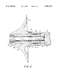
- FIG. 1 shows, in longitudinal section, a first embodiment of the bladed wheel attachment according to the invention.
- the bladed wheel 1 here only generally illustrated, is a radial bladed wheel having a sleeve-type extension 3 extending in the direction of shaft part 2.
- the fastening unit according to the invention is arranged substantially in this extension 3.
- the fastening unit consists of a clamping bushing 4, which has a step 5, extending outwardly in a collar-like fashion at one end.
- a total of four clamping elements 6, 6', 6", 6'" in the form of tapered ring pairs are arranged on the outer cylindrical surface of the clamping bushing 4.
- step 5 of clamping bushing 4 forms a stop in the direction of one of the sides.
- the sleeve 7 is supported at its other free end by a nut 9, which engages a locking screw 8, the latter extending through a boring 43 in the clamping bushing 4.
- the nut 9 moves in a cylindrical recess 10 of the shaft part 2.
- the four clamping elements 6 through 6'" are arranged in such a way that the sloping sections of two clamping elements 6, 6' decline in the direction of the shaft part 2 and the sloping sections of the next two clamping elements 6", 6'" decline in the opposite direction. This arrangement allows optimal use to be made of the effect of the clamping elements 6 through 6'".
- the assembly of the structure is carried out by inserting the fastening unit, including the locking screw 8, into the sleeve-type extension 3 of the bladed wheel 1. Specifically, the unit is inserted until the front face 11 of the clamping bushing 4 that faces the bladed wheel 1 comes to rest on the inner side 12 of the sleeve-like extension 3. The bladed wheel 1, together with the fastening unit, is then inserted into the cylindrical recess 10 of the shaft part 2 until the front face 13 of the thicker-walled bushing 17 of the recess 10 of the shaft part 2 comes to rest on the bladed wheel 1.
- the wheel 1 and shaft 2 are tangentially affixed by an adjustment pin 14 which is placed securely in the blind hole boring of the wheel 1 and, with play, into that of the shaft part 2. This measure avoids double fitting with respect to the interaction of the shaft part 2 with the sleeve-type extension 3 of the bladed wheel. Tightening is carried out by means of an inner hexagonal spanner (not shown here), which is inserted through the bore 15 of the bladed wheel 1 up to the head 16 of the locking screw 8. Rotating the locking screw 8 causes the nut 9 to be moved axially, so that pressure is exerted on the clamping elements 6 through 6'" via the sleeve 7. Because of their declining orientation or slant, the clamping elements are able to deviate radially.
- the clamping elements are able to deform in such a way that a high normal force is produced by the pressure against the inner wall of the sleeve-type extension 3.
- the result of the elastic expansion of the sleeve-type extension 3 is that the extension 3 is pressed against the thicker-walled bushing 17 of the recess 10 of the shaft part 2.
- the thickness of the sleeve 17 in the area of the recess 10 is such that the normal force produced by the fastening unit can be absorbed without permanent deformation.
- Torque is transmitted between the shaft part 2 and the bladed wheel 1 by means of the frictional lock produced by the normal force between the bushing 17 of the recess 10 of the shaft part 2 and the sleeve-type extension 3 of the bladed wheel 1.
- the latter are lubricated with grease such as molycote.
- Other lubricants are also suitable.
- the reduction of the frictional coefficient enables one to make better use of the effect of the clamping elements 6 through 6'” such as permitting the selection of a smaller locking screw 8.
- the selected frictional coefficient between the sleeve-type extension 3 of the bladed wheel 1 and the thicker-walled sleeve 17 of the shaft part 2 should be as large as possible, because as mentioned above, the torque is transmitted at this point.
- FIG. 2 shows another embodiment of the invention in the same longitudinal section as in FIG. 1.
- the same reference numerals have been used for the same parts.
- the bladed wheel 20 is placed on a flange-type journal 24.
- the journal 24 also has a sleeve-type extension 25.
- a one-part nut element 23 can be placed onto the clamping bushing 4 to produce a counterpressure.
- the slopes of the clamping elements 6 through 6'" all decline in the direction of the shaft part 2.
- the assembly is somewhat different than that for the FIG. 1 embodiment.
- the bladed wheel 20 is secured to the flange-like journal 24, e.g., by shrinkage.
- the fastening unit is inserted into the sleeve-type extension 25 and the locking screw 21 is loosely turned.
- the bladed wheel 20, together with the fastening unit is then placed into the recess 10 of the shaft part 2.
- the adjustment pin 14 again serves for tangential fixation.
- an inner hexagonal spanner (not shown) to the head 22 of the locking screw 21, it is possible to turn the latter and thus to move the nut 23 axially.
- the head 22 of the locking screw 21 comes to rest on the front face 26 of the recess 27 of the journal 24.
- a sufficient normal force for the required frictional lock between the sleeve-type extension 25 of the journal 24 and the thicker-walled bushing 17 of the shaft part 2 is then produced in the same manner as in the embodiment of FIG. 1.
- FIG. 3 shows another embodiment in the same longitudinal section as in FIGS. 1 and 2. Again, the same reference numerals are used for the same parts.
- this embodiment in contrast to FIG. 1, no separate nut is used. Rather, the nut is formed by a threaded bore 31 arranged in the shaft part 30.
- the locking screw 8 can be screwed into the threaded bore 31.
- this structure has a reduced length but has improved rigidity of the connection because the bushing 17 is considerably shorter than that of the FIG. 1 embodiment.
- the threaded bore 31 in the shaft part 30 must be carefully produced so that no notch stresses that reduce the alternate strength are created. Assembly is comparable to that described in connection with FIG. 1 so that no further explanation is necessary.
- FIG. 4 shows another embodiment in the same longitudinal section as in FIGS. 1 to 3.
- the same reference numerals are again used for the same parts.
- a threaded bore 41 instead of a smooth bore, is arranged in the clamping bushing 40.
- the threaded bore 41 is oriented so as to be parallel to the axis of the threaded bore 31 in the shaft part 30.
- the first threaded bore 41 in the clamping bushing 40 has a larger diameter, so that the locking screw 8 can be inserted therethrough.
- the bore 42 in the bladed wheel 1 is expanded, specifically, in such a way that the boring is somewhat larger than the screw head 16 of the locking screw 8.
- This arrangement has the advantage that in the event of difficulties in the automatic loosening of the fastening unit, an auxiliary screw (not shown) can be screwed into the threaded bore 41 of the clamping bushing 40 to slightly press back the fastening unit.
- a wheel cap (not shown here) can be provided as needed.
- the journal of the wheel cap would be inserted into the boring 15, 42 (FIGS. 1, 3, 4) of the bladed wheel or into the recess of the screw head 22 of the locking screw 21 (FIG. 2).
- FIG. 5 shows a variation of the embodiment of FIG. 4.
- the thicker-walled bushing 17 of the recess 10 of the shaft part 30 has a collar 44 that is directed toward the bladed wheel 1 and encompasses the journal-type end 45 of the bladed wheel 1.
- a seal 46 e.g., an O-ring, is arranged in a ring nut. This measure prevents the medium that flows down on the rear of the bladed wheel from penetrating into the area of the fastening unit.
- a closing screw 48 instead of a wheel cap, is screwed into a threaded blind hole boring 47 which is arranged in the front face region of the bore 42 of the bladed wheel 1.
- This closing screw 48 serves as a seal of the fastening unit.
- the selected diameter of the threaded blind hole boring 47 is such that the head 16 of the locking screw 8 can be easily inserted through the boring 47.
Landscapes
- Engineering & Computer Science (AREA)
- General Engineering & Computer Science (AREA)
- Mechanical Engineering (AREA)
- Structures Of Non-Positive Displacement Pumps (AREA)
- Turbine Rotor Nozzle Sealing (AREA)
Abstract
Description
Claims (17)
Applications Claiming Priority (2)
| Application Number | Priority Date | Filing Date | Title |
|---|---|---|---|
| DE19627346 | 1996-07-01 | ||
| DE19627346A DE19627346C1 (en) | 1996-07-01 | 1996-07-01 | Device for releasably attaching an impeller to a turbomachine |
Publications (1)
| Publication Number | Publication Date |
|---|---|
| US5961247A true US5961247A (en) | 1999-10-05 |
Family
ID=7799159
Family Applications (1)
| Application Number | Title | Priority Date | Filing Date |
|---|---|---|---|
| US08/885,019 Expired - Fee Related US5961247A (en) | 1996-07-01 | 1997-06-30 | Mechanism for the detachable attachment of a bladed wheel to a turbomachine |
Country Status (3)
| Country | Link |
|---|---|
| US (1) | US5961247A (en) |
| EP (1) | EP0816634B1 (en) |
| DE (2) | DE19627346C1 (en) |
Cited By (17)
| Publication number | Priority date | Publication date | Assignee | Title |
|---|---|---|---|---|
| US6305906B1 (en) * | 1999-02-03 | 2001-10-23 | Itt Manufacturing Enterprises, Inc. | Device for attaching pump impeller |
| US6375383B1 (en) * | 1999-05-11 | 2002-04-23 | Skf Mekan Ab | Attachment device |
| US6499969B1 (en) | 2000-05-10 | 2002-12-31 | General Motors Corporation | Conically jointed turbocharger rotor |
| WO2003093651A1 (en) * | 2002-05-06 | 2003-11-13 | Abb Turbo Systems Ag | Device for fixing a rotor on a shaft |
| US6666461B1 (en) * | 1999-12-20 | 2003-12-23 | Schunk Gmbh & Co. Kg Fabrik Fur Spann-Und Graifwerkzeuge | Clamping chuck |
| US20060067771A1 (en) * | 2004-09-28 | 2006-03-30 | Toshiba Tec Kabushiki Kaisha | Sheet post-process apparatus and waiting tray |
| US20080080966A1 (en) * | 2006-09-29 | 2008-04-03 | Jtket Corporation | Turbocharger |
| WO2014195091A1 (en) | 2013-06-04 | 2014-12-11 | Siemens Aktiengesellschaft | Gas turbine tie shaft arrangement comprising a shell disposed between the tie shaft and the rotor |
| US20150198043A1 (en) * | 2014-01-16 | 2015-07-16 | Bosch Mahle Turbo Systems Gmbh & Co. Kg | Rotor for a turbine or a compressor or a turbine/compressor geometry |
| US20150267712A1 (en) * | 2012-10-15 | 2015-09-24 | Continental Automotive Gmbh | Exhaust gas turbocharger shaft having an impeller |
| CN107091119A (en) * | 2017-06-14 | 2017-08-25 | 南京航空航天大学 | Magnetic suspension turbo-expander impeller of rotor assembly and its localization method |
| US20180062467A1 (en) * | 2015-04-01 | 2018-03-01 | Liebherr-Aerospace Toulouse Sas | Rotor assembly and turbine engine with gas bearings including such a rotor assembly |
| US10014739B2 (en) | 2014-03-25 | 2018-07-03 | Trane International Inc. | Methods and systems to mount a rotor to a shaft |
| US11421581B2 (en) * | 2018-05-24 | 2022-08-23 | Ihi Corporation | Rotating body and turbocharger |
| US11428158B2 (en) * | 2016-01-19 | 2022-08-30 | Robert Bosch Gmbh | Shaft-hub connection |
| US20240110600A1 (en) * | 2022-10-04 | 2024-04-04 | Atlas Copco Comptec, Llc | Adapter for torque transmission between two rotatable components |
| US20260063136A1 (en) * | 2022-09-01 | 2026-03-05 | Mitsubishi Heavy Industries Compressor Corporation | Rotor, rotary machine, and method for assembling rotor |
Families Citing this family (2)
| Publication number | Priority date | Publication date | Assignee | Title |
|---|---|---|---|---|
| DE102007058514A1 (en) * | 2007-12-05 | 2009-06-10 | Zf Friedrichshafen Ag | Multiple disk coupling arrangement for input shaft of vehicle compressor, has carrier brought in rotational coupling engagement with shaft through axial tooth formations and firmly connected by screw bolt penetrating axially to shaft |
| DE102013110727A1 (en) * | 2013-09-27 | 2015-04-02 | Abb Turbo Systems Ag | Compressor arrangement for a turbocharger |
Citations (22)
| Publication number | Priority date | Publication date | Assignee | Title |
|---|---|---|---|---|
| CH269605A (en) * | 1948-11-24 | 1950-07-15 | Tech Studien Ag | Rotor for centrifugal machines. |
| US2577134A (en) * | 1949-02-19 | 1951-12-04 | Elliott Co | Radial spline impeller drive for turbochargers |
| US2602683A (en) * | 1945-03-03 | 1952-07-08 | Sulzer Ag | Rotor for turbomachines |
| GB704139A (en) * | 1951-09-13 | 1954-02-17 | Ringfeder Gmbh | Improvements in or relating to connections between pins and bores |
| US2755093A (en) * | 1953-01-02 | 1956-07-17 | Oskar E Peter | Clamping means |
| US2843311A (en) * | 1954-11-27 | 1958-07-15 | Alfred J Buchi | Coupling devices |
| DE973550C (en) * | 1949-05-14 | 1960-03-24 | Grosskraftwerk Mannheim A G | Individual fastening of running wheels of multi-stage power or working machines by means of split or slotted support rings inserted in the annular grooves of the shaft |
| DE1095064B (en) * | 1959-01-17 | 1960-12-15 | Oskar E Peter | Clamping element for connecting hubs to a shaft |
| DE1110476B (en) * | 1959-03-05 | 1961-07-06 | Oskar E Peter | Clamping element for connecting hubs to a shaft |
| US3009747A (en) * | 1956-11-23 | 1961-11-21 | Paul Gross | Bushing |
| DE1475380A1 (en) * | 1965-05-22 | 1969-04-24 | Kloeckner Humboldt Deutz Ag | Centering for disks attached to rapidly rotating shafts |
| US3941506A (en) * | 1974-09-05 | 1976-03-02 | Carrier Corporation | Rotor assembly |
| US4089613A (en) * | 1977-02-09 | 1978-05-16 | Caterpillar Tractor Co. | Eccentric pin and bushing means for mounting misaligned components |
| US4311224A (en) * | 1978-08-24 | 1982-01-19 | Kabushiki Kaisha Sankyo Seisakujo | Torque limiter |
| US4340317A (en) * | 1981-05-07 | 1982-07-20 | Northern Research & Engineering Corp. | Splineless coupling means |
| GB2102536A (en) * | 1981-07-24 | 1983-02-02 | Mtu Muenchen Gmbh | Improved connection between a ceramic rotor and a metallic driving shaft |
| DE3532348A1 (en) * | 1984-09-19 | 1986-03-27 | Volkswagen AG, 3180 Wolfsburg | Rotor for an exhaust turbocharger |
| DE3625996A1 (en) * | 1986-07-31 | 1988-02-04 | Kuehnle Kopp Kausch Ag | Rotor for an exhaust turbocharger |
| WO1989004228A2 (en) * | 1987-10-30 | 1989-05-18 | Cooper Industries, Inc. | Airfeed peck drill configuration |
| EP0342520A1 (en) * | 1988-05-17 | 1989-11-23 | Elektroschmelzwerk Kempten GmbH | Turbo machine rotor with mechanically linked elements |
| SU1656220A1 (en) * | 1989-01-13 | 1991-06-15 | С.В.Кравчук | Fastening of hub on shaft end |
| DE4445297C1 (en) * | 1994-12-19 | 1996-03-14 | Man B & W Diesel Ag | Rotor wheel for turbo machine esp. radial compressor |
Family Cites Families (2)
| Publication number | Priority date | Publication date | Assignee | Title |
|---|---|---|---|---|
| US4934138A (en) * | 1988-12-06 | 1990-06-19 | Allied-Signal Inc. | High temperature turbine engine structure |
| DE4220127C1 (en) * | 1992-06-17 | 1993-09-16 | Mannesmann Ag, 40213 Duesseldorf, De |
-
1996
- 1996-07-01 DE DE19627346A patent/DE19627346C1/en not_active Expired - Fee Related
-
1997
- 1997-06-30 US US08/885,019 patent/US5961247A/en not_active Expired - Fee Related
- 1997-07-01 DE DE59708353T patent/DE59708353D1/en not_active Expired - Fee Related
- 1997-07-01 EP EP97250202A patent/EP0816634B1/en not_active Expired - Lifetime
Patent Citations (22)
| Publication number | Priority date | Publication date | Assignee | Title |
|---|---|---|---|---|
| US2602683A (en) * | 1945-03-03 | 1952-07-08 | Sulzer Ag | Rotor for turbomachines |
| CH269605A (en) * | 1948-11-24 | 1950-07-15 | Tech Studien Ag | Rotor for centrifugal machines. |
| US2577134A (en) * | 1949-02-19 | 1951-12-04 | Elliott Co | Radial spline impeller drive for turbochargers |
| DE973550C (en) * | 1949-05-14 | 1960-03-24 | Grosskraftwerk Mannheim A G | Individual fastening of running wheels of multi-stage power or working machines by means of split or slotted support rings inserted in the annular grooves of the shaft |
| GB704139A (en) * | 1951-09-13 | 1954-02-17 | Ringfeder Gmbh | Improvements in or relating to connections between pins and bores |
| US2755093A (en) * | 1953-01-02 | 1956-07-17 | Oskar E Peter | Clamping means |
| US2843311A (en) * | 1954-11-27 | 1958-07-15 | Alfred J Buchi | Coupling devices |
| US3009747A (en) * | 1956-11-23 | 1961-11-21 | Paul Gross | Bushing |
| DE1095064B (en) * | 1959-01-17 | 1960-12-15 | Oskar E Peter | Clamping element for connecting hubs to a shaft |
| DE1110476B (en) * | 1959-03-05 | 1961-07-06 | Oskar E Peter | Clamping element for connecting hubs to a shaft |
| DE1475380A1 (en) * | 1965-05-22 | 1969-04-24 | Kloeckner Humboldt Deutz Ag | Centering for disks attached to rapidly rotating shafts |
| US3941506A (en) * | 1974-09-05 | 1976-03-02 | Carrier Corporation | Rotor assembly |
| US4089613A (en) * | 1977-02-09 | 1978-05-16 | Caterpillar Tractor Co. | Eccentric pin and bushing means for mounting misaligned components |
| US4311224A (en) * | 1978-08-24 | 1982-01-19 | Kabushiki Kaisha Sankyo Seisakujo | Torque limiter |
| US4340317A (en) * | 1981-05-07 | 1982-07-20 | Northern Research & Engineering Corp. | Splineless coupling means |
| GB2102536A (en) * | 1981-07-24 | 1983-02-02 | Mtu Muenchen Gmbh | Improved connection between a ceramic rotor and a metallic driving shaft |
| DE3532348A1 (en) * | 1984-09-19 | 1986-03-27 | Volkswagen AG, 3180 Wolfsburg | Rotor for an exhaust turbocharger |
| DE3625996A1 (en) * | 1986-07-31 | 1988-02-04 | Kuehnle Kopp Kausch Ag | Rotor for an exhaust turbocharger |
| WO1989004228A2 (en) * | 1987-10-30 | 1989-05-18 | Cooper Industries, Inc. | Airfeed peck drill configuration |
| EP0342520A1 (en) * | 1988-05-17 | 1989-11-23 | Elektroschmelzwerk Kempten GmbH | Turbo machine rotor with mechanically linked elements |
| SU1656220A1 (en) * | 1989-01-13 | 1991-06-15 | С.В.Кравчук | Fastening of hub on shaft end |
| DE4445297C1 (en) * | 1994-12-19 | 1996-03-14 | Man B & W Diesel Ag | Rotor wheel for turbo machine esp. radial compressor |
Cited By (27)
| Publication number | Priority date | Publication date | Assignee | Title |
|---|---|---|---|---|
| US6305906B1 (en) * | 1999-02-03 | 2001-10-23 | Itt Manufacturing Enterprises, Inc. | Device for attaching pump impeller |
| US6375383B1 (en) * | 1999-05-11 | 2002-04-23 | Skf Mekan Ab | Attachment device |
| US6666461B1 (en) * | 1999-12-20 | 2003-12-23 | Schunk Gmbh & Co. Kg Fabrik Fur Spann-Und Graifwerkzeuge | Clamping chuck |
| US6499969B1 (en) | 2000-05-10 | 2002-12-31 | General Motors Corporation | Conically jointed turbocharger rotor |
| EP1273757A1 (en) * | 2000-05-10 | 2003-01-08 | General Motors Corporation | Conically jointed turbocharger rotor |
| WO2003093651A1 (en) * | 2002-05-06 | 2003-11-13 | Abb Turbo Systems Ag | Device for fixing a rotor on a shaft |
| US20050232775A1 (en) * | 2002-05-06 | 2005-10-20 | Abb Turbo Systems Ag | Device for fixing a rotor on a shaft |
| CN1329629C (en) * | 2002-05-06 | 2007-08-01 | Abb涡轮系统有限公司 | Device for fixing a rotor on a shaft |
| US7374402B2 (en) | 2002-05-06 | 2008-05-20 | Abb Turbo Systems Ag | Fastening arrangement for an impeller on a shaft |
| US20060067771A1 (en) * | 2004-09-28 | 2006-03-30 | Toshiba Tec Kabushiki Kaisha | Sheet post-process apparatus and waiting tray |
| US20080080966A1 (en) * | 2006-09-29 | 2008-04-03 | Jtket Corporation | Turbocharger |
| US8308431B2 (en) * | 2006-09-29 | 2012-11-13 | Jtekt Corporation | Turbocharger |
| US9879693B2 (en) * | 2012-10-15 | 2018-01-30 | Continental Automotive Gmbh | Exhaust gas turbocharger shaft having an impeller |
| US20150267712A1 (en) * | 2012-10-15 | 2015-09-24 | Continental Automotive Gmbh | Exhaust gas turbocharger shaft having an impeller |
| EP3004551A1 (en) * | 2013-06-04 | 2016-04-13 | Siemens Aktiengesellschaft | Gas turbine tie shaft arrangement comprising a shell disposed between the tie shaft and the rotor |
| WO2014195091A1 (en) | 2013-06-04 | 2014-12-11 | Siemens Aktiengesellschaft | Gas turbine tie shaft arrangement comprising a shell disposed between the tie shaft and the rotor |
| US20150198043A1 (en) * | 2014-01-16 | 2015-07-16 | Bosch Mahle Turbo Systems Gmbh & Co. Kg | Rotor for a turbine or a compressor or a turbine/compressor geometry |
| US9803482B2 (en) * | 2014-01-16 | 2017-10-31 | Bosch Mahle Turbo Systems Gmbh & Co. Kg | Rotor for a turbine or a compressor or a turbine/compressor geometry |
| US10014739B2 (en) | 2014-03-25 | 2018-07-03 | Trane International Inc. | Methods and systems to mount a rotor to a shaft |
| US10404117B2 (en) | 2014-03-25 | 2019-09-03 | Trane International Inc. | Methods and systems to mount a rotor to a shaft |
| US10578117B2 (en) * | 2015-04-01 | 2020-03-03 | Liebherr-Aerospace Toulouse Sas | Rotor assembly and turbine engine with gas bearings including such a rotor assembly |
| US20180062467A1 (en) * | 2015-04-01 | 2018-03-01 | Liebherr-Aerospace Toulouse Sas | Rotor assembly and turbine engine with gas bearings including such a rotor assembly |
| US11428158B2 (en) * | 2016-01-19 | 2022-08-30 | Robert Bosch Gmbh | Shaft-hub connection |
| CN107091119A (en) * | 2017-06-14 | 2017-08-25 | 南京航空航天大学 | Magnetic suspension turbo-expander impeller of rotor assembly and its localization method |
| US11421581B2 (en) * | 2018-05-24 | 2022-08-23 | Ihi Corporation | Rotating body and turbocharger |
| US20260063136A1 (en) * | 2022-09-01 | 2026-03-05 | Mitsubishi Heavy Industries Compressor Corporation | Rotor, rotary machine, and method for assembling rotor |
| US20240110600A1 (en) * | 2022-10-04 | 2024-04-04 | Atlas Copco Comptec, Llc | Adapter for torque transmission between two rotatable components |
Also Published As
| Publication number | Publication date |
|---|---|
| EP0816634A1 (en) | 1998-01-07 |
| DE19627346C1 (en) | 1997-11-20 |
| DE59708353D1 (en) | 2002-11-07 |
| EP0816634B1 (en) | 2002-10-02 |
Similar Documents
| Publication | Publication Date | Title |
|---|---|---|
| US5961247A (en) | Mechanism for the detachable attachment of a bladed wheel to a turbomachine | |
| US4334599A (en) | Disc brake and mounting pin assembly therefor | |
| US5775831A (en) | Connected component assembly having conical clamping sleves | |
| US6422657B2 (en) | Vehicle wheel hub mounting system | |
| US4280598A (en) | Brake disk | |
| GB2329685A (en) | Threaded pipe connection | |
| US4835428A (en) | Setting device for vehicle generator | |
| US5720086A (en) | Clamping collar | |
| US5855462A (en) | Cone bolt-connection for multi-disc shaft clutches having first and second clamping sleeves | |
| JP4291536B2 (en) | Radial flow compressor impeller mounting device | |
| HUT71749A (en) | Stress checking member for screwed joints | |
| US6039497A (en) | Method for coupling and a coupling device | |
| US5269622A (en) | Taper clamping unit | |
| US6575659B1 (en) | Conical screw connection for multi-disk shaft couplings | |
| US4114416A (en) | Rolling disc attachment | |
| US7621817B2 (en) | Constant velocity joint-wheel hub assembly with a hollow connection | |
| US5558457A (en) | Chucking device for fixing a hollow shaft to a shaft | |
| JP3387920B2 (en) | Tool coupling with radially elastically expandable connection sleeve and shaft with clamping body | |
| US20140227029A1 (en) | Hollow shaft coupling | |
| US5476337A (en) | Conical gripping arrangement | |
| US3972635A (en) | Double conical hub-to-shaft connection | |
| US4819768A (en) | Actuating device for a disc brake for automotive vehicles | |
| US5407047A (en) | Arrangement for securing a clutch to a crankshaft | |
| JP3755986B2 (en) | Fastening method | |
| US6227829B1 (en) | Eccentric screw pump |
Legal Events
| Date | Code | Title | Description |
|---|---|---|---|
| AS | Assignment |
Owner name: MANNESMANN AKTIENGESELLSCHAFT, GERMANY Free format text: ASSIGNMENT OF ASSIGNORS INTEREST;ASSIGNORS:GOLD, PETER WERNER;CASPER, THOMAS;REEL/FRAME:008718/0501 Effective date: 19970626 |
|
| FEPP | Fee payment procedure |
Free format text: PAYOR NUMBER ASSIGNED (ORIGINAL EVENT CODE: ASPN); ENTITY STATUS OF PATENT OWNER: LARGE ENTITY |
|
| FPAY | Fee payment |
Year of fee payment: 4 |
|
| FPAY | Fee payment |
Year of fee payment: 8 |
|
| REMI | Maintenance fee reminder mailed | ||
| LAPS | Lapse for failure to pay maintenance fees | ||
| STCH | Information on status: patent discontinuation |
Free format text: PATENT EXPIRED DUE TO NONPAYMENT OF MAINTENANCE FEES UNDER 37 CFR 1.362 |
|
| FP | Lapsed due to failure to pay maintenance fee |
Effective date: 20111005 |