US5961145A - Mobile machine with laterally pivoted supporting struts - Google Patents
Mobile machine with laterally pivoted supporting struts Download PDFInfo
- Publication number
- US5961145A US5961145A US09/011,863 US1186398A US5961145A US 5961145 A US5961145 A US 5961145A US 1186398 A US1186398 A US 1186398A US 5961145 A US5961145 A US 5961145A
- Authority
- US
- United States
- Prior art keywords
- supporting
- strut
- supporting strut
- chassis
- mobile machine
- Prior art date
- Legal status (The legal status is an assumption and is not a legal conclusion. Google has not performed a legal analysis and makes no representation as to the accuracy of the status listed.)
- Expired - Fee Related
Links
- 230000007246 mechanism Effects 0.000 claims abstract description 20
- 210000000078 claw Anatomy 0.000 claims description 5
- 239000013536 elastomeric material Substances 0.000 claims description 3
- 230000008878 coupling Effects 0.000 claims description 2
- 238000010168 coupling process Methods 0.000 claims description 2
- 238000005859 coupling reaction Methods 0.000 claims description 2
- 238000006073 displacement reaction Methods 0.000 claims 2
- 238000005406 washing Methods 0.000 description 7
- 230000008901 benefit Effects 0.000 description 2
- 230000006872 improvement Effects 0.000 description 2
- 230000009471 action Effects 0.000 description 1
- 230000005540 biological transmission Effects 0.000 description 1
- 238000010276 construction Methods 0.000 description 1
Images


Classifications
-
- B—PERFORMING OPERATIONS; TRANSPORTING
- B08—CLEANING
- B08B—CLEANING IN GENERAL; PREVENTION OF FOULING IN GENERAL
- B08B1/00—Cleaning by methods involving the use of tools
- B08B1/30—Cleaning by methods involving the use of tools by movement of cleaning members over a surface
- B08B1/32—Cleaning by methods involving the use of tools by movement of cleaning members over a surface using rotary cleaning members
-
- B—PERFORMING OPERATIONS; TRANSPORTING
- B60—VEHICLES IN GENERAL
- B60S—SERVICING, CLEANING, REPAIRING, SUPPORTING, LIFTING, OR MANOEUVRING OF VEHICLES, NOT OTHERWISE PROVIDED FOR
- B60S9/00—Ground-engaging vehicle fittings for supporting, lifting, or manoeuvring the vehicle, wholly or in part, e.g. built-in jacks
- B60S9/02—Ground-engaging vehicle fittings for supporting, lifting, or manoeuvring the vehicle, wholly or in part, e.g. built-in jacks for only lifting or supporting
- B60S9/10—Ground-engaging vehicle fittings for supporting, lifting, or manoeuvring the vehicle, wholly or in part, e.g. built-in jacks for only lifting or supporting by fluid pressure
Definitions
- the invention is related to a mobile machine, having a multi-axle vehicle chassis carrying the machine and at least one supporting strut which is pivotal about a pivot axis parallel to the vertical axis of the vehicle on the vehicle chassis or a support frame fixed to the vehicle chassis from an inoperative position in which it is pivoted against a longitudinal side of the chassis into a laterally pivoted supporting position, the free end of which supporting strut is adapted to be supported on the ground by means of a preferably vertically extendable foot portion.
- the solution according to the invention is based on the idea that the supporting struts are secured against rotation in the region of their pivot bearing in the laterally pivoted position. According to the invention, this is obtained by providing a locking mechanism which prevents the supporting strut from rotating about its pivot axis in its laterally pivoted supporting position.
- the supporting strut in its laterally pivoted supporting position is limitedly movable with respect to the chassis between a locking position and a releasing position of the locking mechanism, parallel to its pivot axis.
- the locking mechanism may comprise a claw coupling which is disposed between axially facing, strut-fixed and chassis-fixed surfaces, and which is adapted to be engaged without free play in the laterally pivoted supporting position by axial lifting of the supporting strut.
- the movement is expediently effected by at least one lifting member which is disposed between the chassis or the support frame on the one hand and the supporting strut on the other hand, and which is preferably designed to be a hydraulic cylinder.
- the supporting strut is borne between two chassis-fixed bearing brackets which are disposed spaced at a distance above each other, such that it can be pivoted as well as lifted and lowered.
- the supporting strut is adapted to be limitedly pivotal about the pivot axis by means of a preferably hydraulic motor.
- the motor comprises a braking or locking member which is adapted to be operated independently of the locking mechanism.
- the motor expediently comprises a torque converter which radially protrudes over its motor casing and which is non-rotatably connected with its free end to the supporting strut at a distance from the pivot axis.
- the foot portion comprises a sole made of an elastomeric material which is preferably corrugated on its bottom side.
- a further preferred embodiment of the invention provides that at least two supporting struts, which are laterally pivotal and secured against rotation in their laterally pivoted supporting position, are disposed on each longitudinal side of the vehicle chassis.
- one supporting leg may be disposed in the rearward region of each longitudinal side of the vehicle chassis, which is rigidly connected to the vehicle chassis or the support frame and which comprises a vertically extendable foot portion.
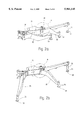
- FIG. 1 shows a side view of a mobile airplane washing device in a raised working position
- FIGS. 2a and b show a section of the support frame of the mobile airplane washing device according to FIG. 1 in a diagrammatical representation with retracted and extended supporting struts;
- FIGS. 3a to e show the details A and B in FIGS. 2a and b in an enlarged representation in a number of different pivot and lift positions of the supporting strut;
- FIGS. 4a and b show the details C and D of FIGS. 3b and c in an enlarged representation.
- the mobile airplane washing device shown in FIG. 1 consists essentially of a vehicle chassis 14 having two front axles 10 and three rear axles 12, an articulated mast 22 which is rotatably borne about a vertical axis 18 on a mast bearer 16 and which carries a washing brush 20 on its free end, and a support construction comprising a chassis-fixed support frame 24, two each forward and center supporting struts 30, 32 which are pivotal about vertical axes 26, 28 on the support frame, and two rearward support legs 34 which are rigidly connected to the support frame 24.
- the supporting struts 30, 32 are borne between two bearing brackets 36 of the support frame 24, pivotally by means of a hydraulic motor 38 and a torque converter 40 about the vertical axes 26, 28 and limitedly movable upwards and downwards by means of two hydraulic cylinders 42, 44 each.
- the cylinder part of the hydraulic cylinders 42, 44 is connected to the supporting struts 30, 32, while the piston rod 42' of the hydraulic cylinder 42 is mounted on the lower and the piston rod 44' of the hydraulic cylinder 44 on the upper bearing bracket 36.
- the torque converter 40 which radially protrudes over the casing of the motor 38 is connected to a driver 46 of the supporting struts 30, 32, which is disposed at a distance from the axis 26 and 28, respectively.
- a guide opening 52 in the torque converter 40 ensures that the driver 46 can move with respect to the torque converter 40 during the lifting and lowering of the supporting struts 30, 32 (see FIGS. 3c and d).
- the hydraulic cylinders 42, 44 are part of a locking mechanism.
- the locking mechanism additionally comprises a support frame-fixed claw ring 48 and a strut-fixed claw ring 50, the locking claws of which can be brought from the unlocked position shown in FIG. 4a into the locked position shown in FIG. 4b by lifting the corresponding supporting strut 30, 32 with the aid of the hydraulic cylinders 42, 44 when the supporting strut 30, 32 is in its laterally pivoted position.
- the supporting struts 30, 32 and the rearward support legs 34 have a foot portion 54 at their free end, which can be lowered toward the ground 56 by hydraulic means, so that the vehicle chassis 14 with its wheels 10, 12 is lifted off from the ground 56 (FIGS. 1, 2b).
- the lowering of the foot portion 54 can be effected only after the supporting struts 30, 32 have been pivoted into their supporting position and the locking mechanism 48, 50 has been brought into its locked position by lifting the supporting struts 30, 32 by means of the hydraulic cylinders 42, 44. With these measures it is ensured that the vertical and horizontal forces and moments transmitted to the vehicle chassis 14 by the airplane washing device can be transmitted to the ground 56 essentially without play or slip.
- foot portions 54 comprise a sole 58 made of an elastomeric material which is corrugated on its bottom side.
- the additionally provided rearward support legs 34 ensure that the dimensions of the supporting struts 30, 32 may be kept to a minimum and that sufficient space for washing agent tanks 60 and control boxes 62 remains between the supporting struts 32 and the rearward support legs 34.
- the invention relates to a mobile machine, having a multi-axle vehicle chassis 14 carrying the machine 16, 20, 22.
- a multi-axle vehicle chassis 14 carrying the machine 16, 20, 22.
- at least one supporting strut 30, 32 which is pivotal about a pivot axis 26, 28 parallel to the vertical axis of the vehicle on the vehicle chassis 14 or a support frame 24 fixed to the vehicle chassis from an inoperative position in which it is pivoted against a longitudinal side of the chassis 14 into a laterally pivoted supporting position, the free end of which supporting strut 30, 32 is adapted to be supported on the ground by means of a preferably vertically extendable foot portion 54.
- each supporting strut 30, 32 is provided with a locking mechanism which prevents the supporting strut 30, 32 from rotating about its pivot axis 26, 28 in its laterally pivoted supporting position.
Landscapes
- Physics & Mathematics (AREA)
- Fluid Mechanics (AREA)
- Engineering & Computer Science (AREA)
- Mechanical Engineering (AREA)
- Vehicle Cleaning, Maintenance, Repair, Refitting, And Outriggers (AREA)
- Jib Cranes (AREA)
- Body Structure For Vehicles (AREA)
Abstract
Description
Claims (11)
Applications Claiming Priority (3)
| Application Number | Priority Date | Filing Date | Title |
|---|---|---|---|
| DE19531697A DE19531697A1 (en) | 1995-08-29 | 1995-08-29 | Mobile working machine with support arms that can be swung out to the side |
| DE19531697 | 1995-08-29 | ||
| PCT/EP1996/002724 WO1997008026A1 (en) | 1995-08-29 | 1996-06-22 | Mobile machine with laterally pivoted supporting struts |
Publications (1)
| Publication Number | Publication Date |
|---|---|
| US5961145A true US5961145A (en) | 1999-10-05 |
Family
ID=7770636
Family Applications (1)
| Application Number | Title | Priority Date | Filing Date |
|---|---|---|---|
| US09/011,863 Expired - Fee Related US5961145A (en) | 1995-08-29 | 1996-06-22 | Mobile machine with laterally pivoted supporting struts |
Country Status (6)
| Country | Link |
|---|---|
| US (1) | US5961145A (en) |
| EP (1) | EP0847348B1 (en) |
| JP (1) | JPH11512047A (en) |
| KR (1) | KR19990044098A (en) |
| DE (2) | DE19531697A1 (en) |
| WO (1) | WO1997008026A1 (en) |
Cited By (16)
| Publication number | Priority date | Publication date | Assignee | Title |
|---|---|---|---|---|
| US6276718B1 (en) * | 1997-08-21 | 2001-08-21 | Putzmeister Aktiengesellschaft | Mobile machine with telescopic support struts |
| US6293586B1 (en) * | 1998-02-12 | 2001-09-25 | Putzmeister Aktiengesellschaft | Mobile working machine with support legs and axle blocking system |
| US6308985B1 (en) * | 1997-08-21 | 2001-10-30 | Putzmeister Aktiengesellschaft | Mobile work machine with telescopic support struts |
| US6390504B1 (en) * | 1998-06-20 | 2002-05-21 | Waitzinger Baumaschinen Vertrieb Und Service Gmbh | Mobile concrete pump |
| WO2002072409A1 (en) * | 2001-03-12 | 2002-09-19 | Putzmeister Aktiengesellschaft | Mobile viscous matter pump comprising a support construction and a pneumatic air-cushioned wheel axle |
| US20030038466A1 (en) * | 2000-07-07 | 2003-02-27 | Dietmar Fugel | Support booms for mobil working machines and mobil concrete pump with said support booms |
| US6715579B1 (en) * | 2002-10-07 | 2004-04-06 | Deere & Company | Articulated frame work vehicle |
| US7062883B1 (en) * | 2001-03-16 | 2006-06-20 | Alltech Communications, L.L.C. | Self guying communication tower |
| US20070012641A1 (en) * | 2003-04-10 | 2007-01-18 | Furukawa Co., Ltd. | Safety device against overturning crane |
| EP1970281A3 (en) * | 2007-03-15 | 2009-09-30 | Colson Castors Limited | Wheeled support device |
| US20100264635A1 (en) * | 2008-02-06 | 2010-10-21 | Putzmeister Concrete Pumps Gmbh | Mobile work machine |
| US20130119007A1 (en) * | 2010-06-23 | 2013-05-16 | Patrick Kramer | Vehicle for transporting ballast weights |
| US20150375974A1 (en) * | 2014-06-27 | 2015-12-31 | Caterpillar Forest Products Inc. | Stabilizer legs for knuckleboom loader |
| US9651085B2 (en) | 2013-04-03 | 2017-05-16 | Putzmeister Engineering Gmbh | Mobile concrete pump and production method |
| US10456610B1 (en) * | 2018-04-23 | 2019-10-29 | Oshkosh Corporation | Stability system for a fire apparatus |
| US10801593B2 (en) | 2017-04-26 | 2020-10-13 | Paratech, Incorporated | Strut extender mechanism |
Families Citing this family (4)
| Publication number | Priority date | Publication date | Assignee | Title |
|---|---|---|---|---|
| JP4763119B2 (en) * | 1999-08-04 | 2011-08-31 | リープヘル−ヴェルク エーインゲン ゲーエムベーハー | Crawler mounted crane |
| DE102008037715B4 (en) | 2008-08-14 | 2019-03-28 | Schwing Gmbh | Mobile machine with swiveling outriggers |
| DE102018110391A1 (en) * | 2018-04-30 | 2019-10-31 | Liebherr-Betonpumpen Gmbh | Truck-mounted concrete pump and swivel leg for a truck-mounted concrete pump |
| DE102018127828A1 (en) * | 2018-11-07 | 2020-05-07 | Liebherr-Betonpumpen Gmbh | Truck-mounted concrete pump |
Citations (7)
| Publication number | Priority date | Publication date | Assignee | Title |
|---|---|---|---|---|
| US769461A (en) * | 1903-10-22 | 1904-09-06 | Erastus S Bennett | Mining machinery. |
| US3854595A (en) * | 1973-05-04 | 1974-12-17 | Demag Baumaschinen Gmbh | Mobile crane |
| US4394913A (en) * | 1980-11-07 | 1983-07-26 | Harnischfeger Corporation | Crane having power operated outriggers and lock means therefor |
| US4761021A (en) * | 1986-06-03 | 1988-08-02 | Andry Lagsdin | Stabilizer pad for earthmoving apparatus |
| US5015008A (en) * | 1990-04-09 | 1991-05-14 | J. I. Case Company | Stabilizer pad assembly for an earth moving apparatus |
| US5135145A (en) * | 1989-09-29 | 1992-08-04 | Graber Products, Inc. | Mountain bike rack |
| US5706960A (en) * | 1995-02-14 | 1998-01-13 | Pioneer Engineering | Extended perimeter x-shaped outrigger assembly for cranes |
Family Cites Families (4)
| Publication number | Priority date | Publication date | Assignee | Title |
|---|---|---|---|---|
| DE2364296C3 (en) * | 1973-12-22 | 1980-01-24 | Fritz 5802 Wetter Metz | Support device for cranes, lifting platforms or the like |
| US4624357A (en) * | 1984-06-25 | 1986-11-25 | Rotec Industries, Inc. | Vehicle-mounted extensible conveyor |
| CH667448A5 (en) * | 1985-02-15 | 1988-10-14 | Ernst Zimmermann | UNDERCARRIAGE OF A HEAVY DUTY VEHICLE, ESPECIALLY A MULTI-AXLE MOBILE CRANE. |
| DE3830315A1 (en) * | 1988-09-07 | 1990-03-08 | Putzmeister Maschf | MOBILE CONCRETE PUMP |
-
1995
- 1995-08-29 DE DE19531697A patent/DE19531697A1/en not_active Withdrawn
-
1996
- 1996-06-22 EP EP96922022A patent/EP0847348B1/en not_active Expired - Lifetime
- 1996-06-22 JP JP9509739A patent/JPH11512047A/en active Pending
- 1996-06-22 US US09/011,863 patent/US5961145A/en not_active Expired - Fee Related
- 1996-06-22 KR KR1019980701331A patent/KR19990044098A/en not_active Application Discontinuation
- 1996-06-22 WO PCT/EP1996/002724 patent/WO1997008026A1/en not_active Application Discontinuation
- 1996-06-22 DE DE59606194T patent/DE59606194D1/en not_active Expired - Fee Related
Patent Citations (7)
| Publication number | Priority date | Publication date | Assignee | Title |
|---|---|---|---|---|
| US769461A (en) * | 1903-10-22 | 1904-09-06 | Erastus S Bennett | Mining machinery. |
| US3854595A (en) * | 1973-05-04 | 1974-12-17 | Demag Baumaschinen Gmbh | Mobile crane |
| US4394913A (en) * | 1980-11-07 | 1983-07-26 | Harnischfeger Corporation | Crane having power operated outriggers and lock means therefor |
| US4761021A (en) * | 1986-06-03 | 1988-08-02 | Andry Lagsdin | Stabilizer pad for earthmoving apparatus |
| US5135145A (en) * | 1989-09-29 | 1992-08-04 | Graber Products, Inc. | Mountain bike rack |
| US5015008A (en) * | 1990-04-09 | 1991-05-14 | J. I. Case Company | Stabilizer pad assembly for an earth moving apparatus |
| US5706960A (en) * | 1995-02-14 | 1998-01-13 | Pioneer Engineering | Extended perimeter x-shaped outrigger assembly for cranes |
Cited By (27)
| Publication number | Priority date | Publication date | Assignee | Title |
|---|---|---|---|---|
| US6308985B1 (en) * | 1997-08-21 | 2001-10-30 | Putzmeister Aktiengesellschaft | Mobile work machine with telescopic support struts |
| US6276718B1 (en) * | 1997-08-21 | 2001-08-21 | Putzmeister Aktiengesellschaft | Mobile machine with telescopic support struts |
| US6293586B1 (en) * | 1998-02-12 | 2001-09-25 | Putzmeister Aktiengesellschaft | Mobile working machine with support legs and axle blocking system |
| US6390504B1 (en) * | 1998-06-20 | 2002-05-21 | Waitzinger Baumaschinen Vertrieb Und Service Gmbh | Mobile concrete pump |
| US20030038466A1 (en) * | 2000-07-07 | 2003-02-27 | Dietmar Fugel | Support booms for mobil working machines and mobil concrete pump with said support booms |
| US6840540B2 (en) * | 2000-07-07 | 2005-01-11 | Putzmeister Aktiengesellschaft | Support struts for mobile working machines and mobile concrete pump with said support struts |
| WO2002072409A1 (en) * | 2001-03-12 | 2002-09-19 | Putzmeister Aktiengesellschaft | Mobile viscous matter pump comprising a support construction and a pneumatic air-cushioned wheel axle |
| US7195258B2 (en) * | 2001-03-12 | 2007-03-27 | Putzmeister Aktiengesellschaft | Mobile thick matter pump comprising a support construction and a pneumatic air-cushioned wheel axle |
| US20040084859A1 (en) * | 2001-03-12 | 2004-05-06 | Wolf-Michael Petzold | Mobile viscous matter pump comprising a support construction and a pneumatic air-cushioned wheel axle |
| US7062883B1 (en) * | 2001-03-16 | 2006-06-20 | Alltech Communications, L.L.C. | Self guying communication tower |
| US6715579B1 (en) * | 2002-10-07 | 2004-04-06 | Deere & Company | Articulated frame work vehicle |
| US20040064978A1 (en) * | 2002-10-07 | 2004-04-08 | Deer & Company, A Delaware Corporation | Articulated frame work vehicle |
| US7364044B2 (en) * | 2003-04-10 | 2008-04-29 | Furukawa Co., Ltd. | Safety device against overturning crane |
| US20070012641A1 (en) * | 2003-04-10 | 2007-01-18 | Furukawa Co., Ltd. | Safety device against overturning crane |
| EP1970281A3 (en) * | 2007-03-15 | 2009-09-30 | Colson Castors Limited | Wheeled support device |
| US20100264635A1 (en) * | 2008-02-06 | 2010-10-21 | Putzmeister Concrete Pumps Gmbh | Mobile work machine |
| US8282130B2 (en) * | 2008-02-06 | 2012-10-09 | Putzmeister Engineering Gmbh | Mobile work machine |
| US20130119007A1 (en) * | 2010-06-23 | 2013-05-16 | Patrick Kramer | Vehicle for transporting ballast weights |
| US9061625B2 (en) * | 2010-06-23 | 2015-06-23 | Patrick Kramer | Vehicle for transporting ballast weights |
| US9651085B2 (en) | 2013-04-03 | 2017-05-16 | Putzmeister Engineering Gmbh | Mobile concrete pump and production method |
| US20150375974A1 (en) * | 2014-06-27 | 2015-12-31 | Caterpillar Forest Products Inc. | Stabilizer legs for knuckleboom loader |
| US10801593B2 (en) | 2017-04-26 | 2020-10-13 | Paratech, Incorporated | Strut extender mechanism |
| US11236808B2 (en) | 2017-04-26 | 2022-02-01 | Paratech, Incorporated | Strut extender mechanism |
| US10456610B1 (en) * | 2018-04-23 | 2019-10-29 | Oshkosh Corporation | Stability system for a fire apparatus |
| US11020621B2 (en) * | 2018-04-23 | 2021-06-01 | Oshkosh Corporation | Stability system for a fire apparatus |
| US11638845B2 (en) | 2018-04-23 | 2023-05-02 | Oshkosh Corporation | Stability system for a fire apparatus |
| US20230226394A1 (en) * | 2018-04-23 | 2023-07-20 | Oshkosh Corporation | Stability system for a fire apparatus |
Also Published As
| Publication number | Publication date |
|---|---|
| KR19990044098A (en) | 1999-06-25 |
| WO1997008026A1 (en) | 1997-03-06 |
| DE19531697A1 (en) | 1997-03-06 |
| EP0847348A1 (en) | 1998-06-17 |
| JPH11512047A (en) | 1999-10-19 |
| EP0847348B1 (en) | 2000-12-06 |
| DE59606194D1 (en) | 2001-01-11 |
Similar Documents
| Publication | Publication Date | Title |
|---|---|---|
| US5961145A (en) | Mobile machine with laterally pivoted supporting struts | |
| US4082197A (en) | Articulated high lift vehicle | |
| US4674944A (en) | Forklift variable reach mechanism | |
| US5118246A (en) | Elevating tailgate for vehicle and process of handling it | |
| US4900055A (en) | Hydraulic retractable and extensible wheel suspension | |
| US6126227A (en) | Covering structure of the driving place of operative machines | |
| ITTO980765A1 (en) | VEHICLE USED AS AN AGRICULTURAL TRACTOR LIFT. | |
| JPS5997994A (en) | Crane car having high load capacity | |
| US3543957A (en) | Fork lift trucks | |
| US6405806B1 (en) | Vehicle implement interface | |
| EP0568758B1 (en) | A multi-use mobile elevator excavator | |
| JPS637999B2 (en) | ||
| CN210505307U (en) | Fork wheel crane | |
| US4269560A (en) | Steering assembly | |
| US4761110A (en) | Vehicle lifting and towing apparatus | |
| IE914571A1 (en) | A load handling vehicle | |
| GB2104867A (en) | Crane | |
| CA1301117C (en) | Transportable, articulated-arm crane comprising three hydraulically actuated members | |
| JPS594600A (en) | Platform for approach | |
| EP0286301B1 (en) | Vehicle-mountable access lift | |
| US3870171A (en) | Lifting mechanism for front end loader | |
| CA1222480A (en) | Automobile vehicle for towing and for hoisting loads | |
| GB2120620A (en) | A breakdown recovery vehicle | |
| KR0138442B1 (en) | Industrial forklift truck having telescopic boom | |
| GB2051182A (en) | Motor graders |
Legal Events
| Date | Code | Title | Description |
|---|---|---|---|
| AS | Assignment |
Owner name: PUTZMEISTER AKTIENGESELLSCHAFT, GERMANY Free format text: ASSIGNMENT OF ASSIGNORS INTEREST;ASSIGNORS:SCHILLINGER, HANS-DIETER;LORINCZ, KLAUS;REEL/FRAME:009116/0852;SIGNING DATES FROM 19980127 TO 19980212 |
|
| FPAY | Fee payment |
Year of fee payment: 4 |
|
| FPAY | Fee payment |
Year of fee payment: 8 |
|
| FEPP | Fee payment procedure |
Free format text: PAYOR NUMBER ASSIGNED (ORIGINAL EVENT CODE: ASPN); ENTITY STATUS OF PATENT OWNER: LARGE ENTITY |
|
| AS | Assignment |
Owner name: PUTZMEISTER CONCRETE PUMPS GMBH, GERMANY Free format text: CHANGE OF NAME;ASSIGNOR:PUTZMEISTER ATIENGESELLSCHAFT;REEL/FRAME:021328/0506 Effective date: 20080425 Owner name: PUTZMEISTER CONCRETE PUMPS GMBH,GERMANY Free format text: CHANGE OF NAME;ASSIGNOR:PUTZMEISTER ATIENGESELLSCHAFT;REEL/FRAME:021328/0506 Effective date: 20080425 |
|
| AS | Assignment |
Owner name: PUTZMEISTER CONCRETE PUMPS GMBH,GERMANY Free format text: RE-RECORD TO CORRECT CONVEYING/RECEIVING PARTY, PREVIOUSLY RECORDED AT REEL/FRAME 021328/0506;ASSIGNOR:PUTZMEISTER AKTIENGESELLSCHAFT;REEL/FRAME:023892/0382 Effective date: 20080425 Owner name: PUTZMEISTER CONCRETE PUMPS GMBH, GERMANY Free format text: RE-RECORD TO CORRECT CONVEYING/RECEIVING PARTY, PREVIOUSLY RECORDED AT REEL/FRAME 021328/0506;ASSIGNOR:PUTZMEISTER AKTIENGESELLSCHAFT;REEL/FRAME:023892/0382 Effective date: 20080425 |
|
| REMI | Maintenance fee reminder mailed | ||
| LAPS | Lapse for failure to pay maintenance fees | ||
| STCH | Information on status: patent discontinuation |
Free format text: PATENT EXPIRED DUE TO NONPAYMENT OF MAINTENANCE FEES UNDER 37 CFR 1.362 |
|
| FP | Lapsed due to failure to pay maintenance fee |
Effective date: 20111005 |