US5953895A - Method and apparatus for pulling and chopping plant stalks - Google Patents
Method and apparatus for pulling and chopping plant stalks Download PDFInfo
- Publication number
- US5953895A US5953895A US08/895,832 US89583297A US5953895A US 5953895 A US5953895 A US 5953895A US 89583297 A US89583297 A US 89583297A US 5953895 A US5953895 A US 5953895A
- Authority
- US
- United States
- Prior art keywords
- frame structure
- plant stalks
- pneumatic tires
- pair
- movement
- Prior art date
- Legal status (The legal status is an assumption and is not a legal conclusion. Google has not performed a legal analysis and makes no representation as to the accuracy of the status listed.)
- Expired - Lifetime
Links
Images


Classifications
-
- A—HUMAN NECESSITIES
- A01—AGRICULTURE; FORESTRY; ANIMAL HUSBANDRY; HUNTING; TRAPPING; FISHING
- A01D—HARVESTING; MOWING
- A01D34/00—Mowers; Mowing apparatus of harvesters
- A01D34/835—Mowers; Mowing apparatus of harvesters specially adapted for particular purposes
- A01D34/8355—Mowers; Mowing apparatus of harvesters specially adapted for particular purposes for cutting up or crushing remaining standing stalks, e.g. stubble
Definitions
- the present invention relates generally to a method and apparatus for pulling and chopping plant stalks, and more particularly, to a method and apparatus for pulling plant stalks and the root system thereof, such as cotton, substantially clear of the ground and then chopping the same.
- the plant root system and stalk stump portion that remain in the field after various crops have been harvested, and the upper part of the stalks have been cut, may amount to more than fifty percent of the total weight or volume of the plant that was left in the field after the crops were harvested.
- Cotton plants have deep tap roots with both the stalk section extending seven to eight inches above the ground and the root system below the ground level being very dense and tough.
- the cotton stalk section usually contains as much as sixty percent of the total weight of the plant after the cotton is harvested and deteriorates very little if left standing in the field until spring tillage begins.
- These stalk sections hinder cultivation, and thus, grass, weeds and other parasite vegetation must be controlled with chemicals.
- the following crop to be planted is peanuts or another crop that must be dug from the ground, these stalk sections also cause major problems in harvesting and cleaning.
- Rotary and flail type cutters are used extensively to cut the non-abrasive top sections of a wide variety of plants.
- the cutting edges on these machines operate at high speed to sever grass, weeds, forage crops or other plants by impact at the desired height above soil surfaces. Should these cutting edges be allowed to touch the soil, they will become dull very quickly. When the cutting edges become dull, they will no longer sever plants on impact, performance deteriorates and power consumption soars beyond acceptable levels. Soil attached to plant roots after they are pulled from the ground is very abrasive and will wear cutting edges very rapidly. When an attempt is made to grind pulled-up cotton stalks with roots attached, cutting edges on the high speed blades become dull within minutes, all cutting ceases, and the cutting or grinding machine becomes plugged and inoperative.
- Cutters such as that shown in U.S. Pat. No. 4,350,207 to Ben-Dor are examples of the above described conventional machinery which have been used for many years. It should be realized, however, that prior art choppers were used for cutting primarily only the upper stalk sections. Even though these choppers did not handle the heavy roots remaining in the ground, many problems were still associated with these type of choppers, especially when used for cutting cotton and similar plant stalks. They were, however, simple choppers and the power requirement was relatively small, which allowed them to be pulled by draft animals without the need for external power transmission drives. Since these choppers replaced vast amounts of manual labor, the requirement for disconnecting, cleaning, sharpening and servicing them frequently was not considered a major factor in years past.
- Blades on prior art rolling chopper cylinders were, therefore, normally mounted at two or more points in a manner to leave a center area between blades open so that part of the chopped material could pass through and reduce wedging between adjacent blades. This worked well on corn and other soft or fragile stalks when the roots remained in the ground and the volume of chopped material is not too great.
- ground engaging rolling choppers of this type were used to cut cotton stalks, however, material accumulated within the center cavity of the rotor and had to be extracted manually. This is a very difficult and time consuming task.
- Additional concerns related to pulling and grinding plant stalks include the soil attached to the root systems of pulled stalks causing the cutting edges of high speed blades to wear away very quickly; flying stalk particles, when propelled at high speed by the cutter blades, puncturing the pneumatic tires when a high speed cutter is operated in association with the puller; complexities in conveying and feeding the pulled stalks into an attached cutter or hammer-mill; and difficulty in mechanically lifting the stalks, the heavy center section of which lies in a straight line and conveying them into a grinding or cutting device after they are discharged to the ground from the puller.
- a further concern with prior art stalk pullers and choppers is being able to transport the machine from one field to another over public roads.
- Implements such as plows, row bedders, planters, and cultivators are mounted on standardized tractor three point hitch systems. These systems allow operators to have precise control over implement position, operating depth and row alignment. Tractor mounted implements are lifted and carried by the tractor at the end of one row, and then transported to another field. Wide mowers, disk harrow and many other farm implements do not need to be closely aligned with a row pattern. These machines extend too far behind the tractor to be lifted so they are usually mounted on wheels and trail behind the tractor. The end sections of these machines must, however, be folded when transported over public roads because of their great width.
- the present invention achieves this and other objects through the provision of an apparatus for pulling and chopping plant stalks after harvesting.
- the apparatus includes a frame structure supported from a ground surface for translatory movement at a predetermined rate and in a predetermined direction along a row of plant stalks and at least one pair of pneumatic tires having their peripheries in pressure contact with each other and thus forming a nip for receiving plant stalks therein.
- the rotating pneumatic tires are disposed at a predetermined angle relative to the ground surface such that a lower portion of the nip precedes an upper portion of the nip during movement of the frame structure.
- a chopper assembly may also be drivingly connected and disposed in alignment with the at least one pair of pneumatic tires.
- the chopper assembly chops the plant stalks after they are pulled from the ground.
- the chopper assembly also engages the ground surface during movement of the frame structure and thereby provides rotational drive to the pair of pneumatic tires.
- the predetermined rotation speed of the pneumatic tires is less than the predetermined rate of movement of the frame structure.
- the present invention thus provides a chopper assembly or rotor with attached ground engaging blades that may be rolled across the pulled stalks with enough pressure to cut them. Also, since the rotor of the present invention operates much slower than high speed rotary, flail or hammer type blades, it is possible to design the rotor using blades made of plowshare type steel that would be self-sharpening, have long service free life and offer other advantages as well.
- the present also provides a mechanism to allow for transporting of a wide apparatus over public roads.
- the rotor assembly includes a center section and at least one end section hingedly connected thereto.
- a rotating mechanism is provided for rotating the end section about a hinge more than ninety degrees relative to a horizontal plane of the center section, in order to thereby obtain a transport position disposed substantially over the center section.
- the rotating mechanism rotates the end section approximately one hundred forty degrees.
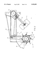
- FIG. 1 is an isometric view of a first embodiment of a stalk puller and rolling chopper in accordance with the present invention
- FIG. 2 is a partial sectional end view thereof showing the chain drives within frame members from the rolling chopper to a right angle gearbox through which the puller wheels are driven;
- FIG. 3 is an end view of the rolling cutter assembly
- FIG. 4 is a top view of a cutter blade
- FIG. 5 is a rear view of a further embodiment of the stalk puller and chopper of the present invention, shown in an operating position;
- FIG. 6 is a rear view thereof, shown in a transport position
- FIG. 7 is a schematic illustration of plant stalks being pulled and chopped by the apparatus of the present invention.
- a stalk puller and rolling chopper apparatus is shown generally by reference numeral 10.
- Apparatus 10 includes a tubular machine frame 12 which supports a plurality of pairs of rotating tires 14, 15 and a rolling chopper cylinder 16.
- One pair of rotating tires 14, 15 is provided for each row of stalks to be pulled, with an aligned chopper 18 disposed therebehind.
- Tires 14, 15 preferably have a six inch or eight inch side wall and a diameter of approximately thirty-two inches, although other suitable diameter tires could of course also be used.
- FIG. 1 illustrates a four row unit, to which similar two, three or four row units may be attached to each side and folded up for transport, as discussed in further detail below.
- Apparatus 10 is preferably manufactured in two, four, six, eight, ten and twelve row models. As shown in FIG. 2, the drives for the tires 14, 15 and the choppers 18 are preferably totally enclosed within the tubular machine frame 12. Each pair of rotating tires 14, 15 and aligned chopper 18 has its own drive system and provisions are provided to allow each folding unit to follow the contour of terraced or irregular land.
- the apparatus 10 is attached to the standard three point hitch of any tractor through the ASAE standard hitch members provided. When aligned with the stalk rows, the apparatus 10 is lowered to the ground and is towed down the rows with the tractor.
- the stalks are bent forward due to the rotation speed of the tires 14, 15 being less than the ground speed of apparatus 10.
- the stalks are aligned with the nip or pinch point 20 between the rotating tires 14, 15.
- rotation of tires 14, 15 causes the stalks and their limbs to be gathered and firmly engaged between the compressed tires 14, 15, which are preferably pneumatic.
- the ground travel speed of apparatus 10 is greater than the rotation speed of the pneumatic tire tread; therefore, the distance that the stalks are pulled from the ground is much more than the distance they would be pulled if the tire perimeter moved as fast as ground speed.
- the dry and brittle cotton stalks are pulled from the ground without breaking the upper stalks from the roots.
- the pairs of pneumatic rubber tires 14, 15 are set at a predetermined angle relative to the ground, preferably forty-five degrees, and compressed by their frame mounted position to the manufacturer's rated load to provide maximum traction at the nip 20 as well as the largest possible area of contact. More particularly, in a preferred embodiment tires 14, 15 have a six or eight inch tread width and a diameter of eighteen inches. Thus, for each of the radial tires having 18" ⁇ 9.5" ⁇ 8" dimensions, it will have an 18" outside diameter, a 9.5" tire width, and an 8" wheel rim diameter. The tread width is calculated as being the given 8" tread width plus each side wall bulging approximately 0.75" for a total tire width of 9.5".
- each of the tires When each of the tires is inflated to its recommended pressure and compressed one inch, it will exert pressure against its spindle shaft slight less than its rated load capacity.
- the side walls of the tires are actually little more than 3.5" after the tire bead drops into the rim, and they are approximately one inch less after being compressed.
- the overall width is thirty-four inches.
- An apparatus 10 can, however, be set up with all sides of adjacent wheels compressed one inch for thirty two inch row spacing.
- the tires 14, 15 are rotated at a speed that will cause the tire perimeter to move slower than ground speed of the apparatus, i.e., the ground speed of the tractor.
- ground speed of the apparatus i.e., the ground speed of the tractor.
- rotation of the tires 14, 15 cause the stalks to be gathered and flow therebetween.
- Pressure from the pneumatic tires 14, 15 holds the stalks as they move through the tire contact area or nip 20.
- a combination of forward movement of the apparatus 10 relative to the ground plus the rotation of the tires 14, 15 at an inclined angle applies adequate force over enough distance and for a sufficient period of time such that the roots are pulled completely from the ground.
- the ground speed of the apparatus 10 will be approximately ten to twelve miles per hour and the tread rotation speed of the tires 14, 15 at the nip 20 will be approximately 6.2-7.4 mph, or approximately sixty-two percent of the ground speed.
- the most efficient tire tread to ground travel ratios may be as low as fifty percent on some crops or as high as seventy-five percent on others. The most efficient ratios depend on the root and stalk characteristics of the plants being pulled, however, the above ratios for cotton plants have been found to be a satisfactory compromise for all types of plants.
- the stalks are already leaning forward, therefore, they are engaged and move between the tires 14, 15 generally parallel to the tire axle shaft 28 at an angle of approximately forty-five degrees relative to the ground in the preferred setup for cotton.
- the plants are toughest near and below the ground and the angle of pull does not cause them to be snapped from the roots.
- Other advantages of the stalks flowing between the tires parallel to the wheel axle shaft include spreading the traction over a longer section with little or no angulation in the weaker upper section of the stalk. When closely adjacent small and large stalks pass between the compressed pneumatic tires, adequate force is applied to both stalks over a substantial portion of their length to assure that the smaller stalk does not slip through any area of lowered traction that might be present closely beside the larger.
- the apparatus 10 of the present invention can optimally perform with a ground speed of approximately 11-12 miles per hour, with an average capacity of 10 acres per hour with a four row model.
- the power required to operate an eight row apparatus under very sandy or stiff land conditions at this speed may exceed 200 hp, with an increased average capacity of eighteen acres per hour.
- the average efficient operating row center tolerance is approximately eight inches, with four inches being provided on each side of the plant row center.
- the tires 14, 15 of apparatus 10 are preferably aligned for thirty-six, thirty-eight, or forty inch row spacings; however, it should be obvious to one skilled in the art that any desired row spacing could, of course, be provided.
- cylinder 16 includes a cutter rotor section or chopper 18 for each row of stalks that apparatus 10 is built to pull and chop.
- Chopper 18 has a preferred width of approximately twenty inches and is centered and aligned directly behind the nip 20 of each pair of rotating tires 14, 15.
- Each chopper 18 includes a plurality of chopper blades 22 that are attached to the enclosed cylinder 16 and that serve as a depth gauge for the choppers 18, as well as the tires 14, 15.
- the blades 22 have a preferred depth of approximately five inches or six inches, which allows for blade wear.
- the tap roots of the plant will clear the ground surface while the upper stalk sections are still held between the pneumatic tires 14, 15, such that rotor blades 22 engage and chop the roots and pull the upper section under the rotor 16 when it is released from the puller tires 14, 15.
- the stalks and roots are chopped in sections short enough to promote deterioration and better seed bed preparation with standard implements.
- Rotors are used to crush clods and mash vegetable matter into the soil in preparing a seed bed for planting but the open center design typical of rolling choppers used in the past hindered this process. If equipped with sharpened blades and enough pressure was applied to cut the root and lower sections of pulled up cotton stalks, the center cavity within the blades of prior art rotors would become packed with stalk sections and the cutting action would cease in minutes. Unlike the rolling cutter assemblies of the prior art, chopper 18 does not have an open space which would allow material to collect and form a packed plug of cut stalk sections, which would cling together and eventually accumulate until the blades stopped performing. Space between blades must always be free of all matter for the vegetation and soil to be chopped.
- the rotor or chopper 18 of the present invention runs clean under virtually all conditions. As the pulled stalks are engaged by the blades 22 of cutter rotor assembly 18, they are pressed into the plant bed, such as the ground surface, until enough resistance from the soil causes them to be severed. As the rotor 18 progresses over the cut section, the leading end of the severed stalk is pressed against blade holder and deflector assembly 24. This action holds the following stalk section in a favorable angle for it to be severed. After it is cut, the trailing end of the stalk section is pressed closer to the rotor center in the region 26 and the cut section is free to leave the rotor assembly with no resistance.
- the blade angle of blades 22 is set to provide the most favorable chopping angle. Blades 22 are formed and set at an angle relative to the chopper cylinder 16 that allows them to penetrate the ground and sever the stalks with minimum resistance, drag or plant bed deformation. This assures longer blade service life as wear is minimized and that which does occur is in a flat plane relative to the flat side of the blade 22.
- the blades 22 are also self-sharpening and remain sharp throughout their useful life without manual grinding.
- Conventional ground engaging rolling blades when used for chopping, soon wear such that the angle from each side of the cutting edge becomes too blunt to cut vegetable matter without frequent grinding. Since the blades 22 of chopper 18 penetrate the ground in such a manner that any wear that does occur is in a flat plane relative to the flat side, that side of the blade 22 wears flat.
- the beveled side of the blade engages the plant bed that was loosened when the blade penetrated. This engagement stabilizes the path of the following blade as it chops the stalk sections and penetrates the ground. It lightly sweeps across the soil on the way up when the beveled side is continuously honed.
- the blades stay very sharp at the cutting edge and the beveled edge retains virtually the same acute angle throughout its service life.
- the blade service life is exceptionally good. Due to the continuous blade honing rotor design, none of the blade material is lost that grinding would remove. The most favorable cutting angle relative to rotor diameter and controlled depth of cut assures minimum blade pressure, therefore, blade wear is less. These features also allow the use of wear resistant plowshare steel with excellent shock resistance that virtually eliminates gaping and breaking by rocks or other hard objects.
- the apparatus 10 is preferably ground driven, such that the ratio of the ground speed to the rotation of the tires 14, 15 remains substantially constant throughout all operating speed ranges. More specifically, as the apparatus 10 is towed down the rows by the tractor, the blades 22 of the chopper 18 are engaging the ground surface, thereby causing chopper 18 to rotate. As chopper 18 rotates, a conventional drive arrangement 30 disposed within cylinder 16 transmits the rotational force through a series of gears or sprockets 32 and a belt or chain drive 34 to the axle or spindle shaft 28 for the tires 14, 15, which in turn causes rotation thereof.
- One of two sprockets on the spindle 28 for the first pair of tires 14, 15 is driven by a sprocket on the right angle gearbox output shaft, a second sprocket on the first spindle shaft 28 drives a first sprocket on the spindle for the second pair of tires 14, 15, and the procedure is repeated to each pair of wheels used.
- Only one tire of each pair of tires 14, 15 is driven by the drive arrangement 30.
- the other tire of each pair of tires 14, 15 is an idler that is driven by the traction from the driven tire.
- This system allows all drive spindles to be driven in the same directions and a simple drive system can be used. All drives are protected by a torque limiter and totally enclosed within the frame.
- each pair of tires may be driven through individual gearboxes. This uses a single chain drive as shown in FIG. 2 which drives a horizontal shaft that passes through each gearbox.
- the rolling chopper can be replaced by ground engaging wheels to drive the stalk puller wheels 14, 15.
- the puller wheels can also be driven by a tractor power take off (PTO), hydraulic motors or by other means, however, it is necessary to synchronize ground to puller wheel speed for best performance and this synchronization must be maintained at all times (i.e., the PTO speed is relative to the tractor speed). If driven from the ground driven rolling chopper or ground wheels, as shown in FIG. 2, the ratio remains constant throughout the range of engine speeds or gear selection the operator chooses to operate.
- PTO tractor power take off
- rod guides may be used to cause two rows to be placed in a single windrow or to be placed in individual rows.
- the apparatus 10 may also be equipped with one or more weight boxes, each designed to accommodate sand, iron, or other dense material when additional weight is required for heavy stalk cutting.
- the weight box(es) may be centered or one disposed on each end of the apparatus.
- the apparatus 10 may also include a row centering coulter and rotating disk guides that move lodged stalks in line with the blades of the chopper.
- the apparatus 10 is preferably manufactured in two, four, six, eight, ten and twelve row models.
- An apparatus which is designed to work eight rows, each row being planted on three foot centers, is therefore at least twenty-four feet wide, and is too wide to be transported over public roads. If the end sections of apparatus 10 were rotated ninety degrees from horizontal, as in the prior art, the resulting overall width of an eight-row apparatus for thirty-six inch rows would be 18.67'. If the end sections were rotated one hundred forty degrees, however, the resulting width would be reduced to 15.58' and a more stable configuration would be obtained.
- Rotation system 50 for allowing the end sections 52a, 52b to rotate more than ninety degrees from the horizontal about a center section 52c.
- Rotation system 50 includes, for each end section, two cylinders 58, 60, each having upper and lower cylinder fluid ports 54, 56. Cylinder fluid ports 54 are connected to a first hydraulic fluid source and cylinder fluid ports 56 are connected to another hydraulic fluid source.
- the cylinders 58, 60 therefore push or pull in unison with identical force and are actuated by a single hydraulic control valve to pivot about a hinge 62 which connects each of the end sections 52a, 52b to the center section 52c.
- a pivoting member 64 is provided to direct the forces from the hydraulic cylinders 58, 60 and thereby cause the end section 52a to pivot about the hinge 62.
- the pivoting member 64 also serves as a stop on which the end sections 52a, 52b will rest when the cylinders are retracted, as shown in FIG. 6 and discussed further below. While only discussed in detail with respect to the end section 52a, it should be apparent that an identical rotating system 50 is provided on the other end of the apparatus for also rotating end section 52b.
- Fluid pressure applied to cylinder fluid ports 54 cause the piston rods 66 to retract with equal force through the pivot points A, B, C, as shown in the operating position of FIG. 5.
- the pivoting member 64 tends to move toward a position that is equal relative to the cylinder frame connecting points A and C.
- the torque about the hinge 62 is greatest at ninety degrees and decreases as the angle then becomes larger or smaller.
- the end section 52a may rotate two degrees below the horizontal relative to the center section 52c when the hydraulic control valve (not shown) is set to a float position.
- the pivoting member 64 can rotate approximately seventy-one degrees about the hinge 62 due to the force from cylinder 58, with cylinder 60 also being able to rotate the pivoting member 64 approximately seventy-one degrees.
- the total rotation of end section 52a about the hinge 62 is approximately one hundred forty-two degrees.
- both cylinders 58, 60 When both cylinders 58, 60 are fully retracted, as shown in the transport position of FIG. 6, the end section 52a rests on the pivoting member 64 and the pivoting member 64 rests on the center section 52c of the apparatus.
- the center of gravity of the end section 52a is to the right, or disposed inward of, the hinge 62, therefore, no fluid pressure is required to hold the end section 52a in the illustrated transport position.
- a safety strap 68 may also be attached, however, in the event that the tractor hydraulic system may leak. Potential hazards associated with the end sections leaking back downward, as is inherent in the prior art, is thus eliminated.
- the rotating system 50 of the present invention includes the pivoting member 64 which allows two cylinders 58, 60 to be used for rotation instead of only the one cylinder employed in conventional systems. Further, since only approximately seventy-one degrees of rotation must be provided by each cylinder, rather than the ninety degrees or more in conventional systems, more favorable crank angles may be used. The maximum force required to rotate the end section 52a through approximately one hundred forty-two degrees of rotation is much less than that required to rotate single cylinder systems only ninety degrees. Furthermore, a lighter frame and simpler cylinder attaching components result in lower fabrication costs and eliminate unnecessary machine weight. Lower hydraulic cylinder force requirements also allow the use of ASAE standard pull type farm implement universal hitch cylinders.
- end sections 52a, 52b are not integral with the center section 52c but hingedly connected thereto and are not attached to any tractor hitch, each section can float or traverse independently over uneven land or terraces. End sections 52a, 52b do have their own power supply from the rotation of the rotors, as described above.
- the rotating system 50 of the present invention provides a more compact unit for transport having a lesser width than that achieved through conventional ninety degree rotation systems.
- the rotating system 50 also achieves a more stable configuration for transport by rotating the end sections approximately one hundred forty two degrees such that the center of gravity of the end section is disposed inward of the effective outer pivot point.
- the use of the pivoting member in combination with two hydraulic cylinders also decreases the overall cost of the required cylinders while improving the efficiency of the same.
Abstract
Description
Claims (14)
Priority Applications (1)
| Application Number | Priority Date | Filing Date | Title |
|---|---|---|---|
| US08/895,832 US5953895A (en) | 1996-07-18 | 1997-07-17 | Method and apparatus for pulling and chopping plant stalks |
Applications Claiming Priority (2)
| Application Number | Priority Date | Filing Date | Title |
|---|---|---|---|
| US2196096P | 1996-07-18 | 1996-07-18 | |
| US08/895,832 US5953895A (en) | 1996-07-18 | 1997-07-17 | Method and apparatus for pulling and chopping plant stalks |
Publications (1)
| Publication Number | Publication Date |
|---|---|
| US5953895A true US5953895A (en) | 1999-09-21 |
Family
ID=26695308
Family Applications (1)
| Application Number | Title | Priority Date | Filing Date |
|---|---|---|---|
| US08/895,832 Expired - Lifetime US5953895A (en) | 1996-07-18 | 1997-07-17 | Method and apparatus for pulling and chopping plant stalks |
Country Status (1)
| Country | Link |
|---|---|
| US (1) | US5953895A (en) |
Cited By (35)
| Publication number | Priority date | Publication date | Assignee | Title |
|---|---|---|---|---|
| US6539697B2 (en) | 2001-02-22 | 2003-04-01 | Carl A. Burk | Apparatus and method for knocking down and crushing farm crop residue |
| US20050269113A1 (en) * | 2004-06-03 | 2005-12-08 | Plessala Erne Jr | Furrow cleaner apparatus |
| US20060266534A1 (en) * | 2004-06-03 | 2006-11-30 | Plessala Erne Jr | Furrow/ditch cleaner apparatus |
| US7562517B1 (en) * | 2008-09-17 | 2009-07-21 | The United States Of America, As Represented By The Secretary Of Agriculture | Rotary crimping apparatus for elevated crop beds |
| US7987917B1 (en) * | 2008-07-09 | 2011-08-02 | The United States Of America As Represented By The Secretary Of Agriculture | Multistage crop roller |
| US20120241177A1 (en) * | 2011-03-21 | 2012-09-27 | Bourquin Daniel T | Organic weed removal apparatus and system |
| CN102792817A (en) * | 2012-06-27 | 2012-11-28 | 新疆机械研究院股份有限公司 | Straight-knife cotton stalk harvesting device |
| WO2013011139A1 (en) * | 2011-07-20 | 2013-01-24 | Cnh Belgium N.V. | Modular agricultural cutting unit for a working machine |
| EP2661949A1 (en) * | 2012-05-09 | 2013-11-13 | IAT-Innovative Agrarmaschinenbau-Technik UG | Cutting device for mechanical processing of harvesting remnants in order to prevent the spread of plant pests and fungal infestation |
| US20140060864A1 (en) * | 2011-07-01 | 2014-03-06 | Charles H. Martin | Agricultural Field Preparation Device |
| US8714276B2 (en) | 2011-03-11 | 2014-05-06 | Great Plains Manufacturing, Inc. | Soil chopping and leveling system |
| US9241438B2 (en) | 2014-02-05 | 2016-01-26 | Dawn Equipment Company | Agricultural system for field preparation |
| US9615497B2 (en) | 2014-02-21 | 2017-04-11 | Dawn Equipment Company | Modular autonomous farm vehicle |
| US9668398B2 (en) | 2014-02-05 | 2017-06-06 | Dawn Equipment Company | Agricultural system for field preparation |
| US9723778B2 (en) | 2014-11-07 | 2017-08-08 | Dawn Equipment Company | Agricultural system |
| US9788472B2 (en) | 2010-09-15 | 2017-10-17 | Dawn Equipment Company | Row unit for agricultural implement |
| US9848522B2 (en) | 2014-11-07 | 2017-12-26 | Dawn Equipment Company | Agricultural system |
| US9861022B2 (en) | 2013-02-01 | 2018-01-09 | Dawn Equipment Company | Agricultural apparatus with hybrid single-disk, double-disk coulter arrangement |
| US9949432B2 (en) | 2015-11-03 | 2018-04-24 | Johan Redekop | Land roller with chopping blades |
| CN108781726A (en) * | 2018-07-11 | 2018-11-13 | 新疆农垦科学院 | Auxiliary dials standing grain pair roller type cotton stalk pull-up |
| CN109258093A (en) * | 2018-11-28 | 2019-01-25 | 农业部南京农业机械化研究所 | Pull out stalk device and cotton-stalk harvester |
| US10444774B2 (en) | 2014-11-07 | 2019-10-15 | Dawn Equipment Company | Agricultural system |
| US10477760B2 (en) | 2015-12-28 | 2019-11-19 | Underground Agriculture, LLC | Agricultural organic device for weed control |
| US10506755B2 (en) | 2010-09-15 | 2019-12-17 | Dawn Equipment Company | Agricultural systems |
| US10548260B2 (en) | 2017-05-04 | 2020-02-04 | Dawn Equipment Company | System for automatically setting the set point of a planter automatic down pressure control system with a seed furrow sidewall compaction measurement device |
| US10582653B2 (en) | 2014-11-07 | 2020-03-10 | Dawn Equipment Company | Agricultural planting system with automatic depth control |
| US10645865B2 (en) | 2017-05-04 | 2020-05-12 | Dawn Equipment Company | Agricultural row unit with automatic control system for furrow closing device |
| US10721855B2 (en) | 2014-02-05 | 2020-07-28 | Dawn Equipment Company | Agricultural system for field preparation |
| US10980163B2 (en) | 2017-02-27 | 2021-04-20 | Kelley Manufacturing Company, Inc. | Stalk puller |
| US10980174B2 (en) | 2015-12-28 | 2021-04-20 | Underground Agriculture, LLC | Agricultural mowing device |
| US11006563B2 (en) | 2017-05-04 | 2021-05-18 | Dawn Equipment Company | Seed firming device for improving seed to soil contact in a planter furrow with feature designed to prevent the buildup of soil on the outer surfaces by discharging pressurized fluid |
| US20210181078A1 (en) * | 2018-06-01 | 2021-06-17 | Monsanto Technology Llc | Rapid stalk strength assessment |
| US11083134B2 (en) | 2015-12-28 | 2021-08-10 | Underground Agriculture, LLC | Agricultural inter-row mowing device |
| US11197411B2 (en) | 2014-11-07 | 2021-12-14 | Dawn Equipment Company | Agricultural planting system with automatic depth control |
| CN114698420A (en) * | 2022-04-15 | 2022-07-05 | 新疆农业大学 | A pull out stalk and smash all-in-one for cotton stalk |
Citations (13)
| Publication number | Priority date | Publication date | Assignee | Title |
|---|---|---|---|---|
| US2553356A (en) * | 1949-04-14 | 1951-05-15 | Carl S Cady | Stubble chopper |
| US2660013A (en) * | 1948-12-04 | 1953-11-24 | William E Priestley | Peanut vine pulling machine |
| US2940528A (en) * | 1956-01-16 | 1960-06-14 | Santa Clara Frosted Foods Co | Method of packing and/or harvesting fruit or vegetable articles from bush type plants |
| US3437152A (en) * | 1965-09-23 | 1969-04-08 | Thomas A Barrentine | Apparatus for pulling stalks |
| US3716974A (en) * | 1971-06-21 | 1973-02-20 | J Wehde | Harvesting attachment for combines |
| US4027733A (en) * | 1975-08-28 | 1977-06-07 | Eisenhardt Fred W | Weed pulling machine |
| US4183411A (en) * | 1978-01-09 | 1980-01-15 | Bourquin Design and Mfg., Inc. | Weed puller apparatus |
| US4350207A (en) * | 1980-08-28 | 1982-09-21 | Ben Dor Yaron | Agricultural implement for the extraction and shredding of stalks and roots |
| US4370846A (en) * | 1980-10-17 | 1983-02-01 | Brouwer Turf Equipment Limited | Gang mower with single cylinder lifting mechanism |
| US4459796A (en) * | 1981-07-10 | 1984-07-17 | Stokes Ralph E | Gathering plant trash |
| US4751812A (en) * | 1985-07-24 | 1988-06-21 | Yacov Lubetzky | Stalk puller and shredder machine |
| US4965991A (en) * | 1989-11-09 | 1990-10-30 | Sauder David E | Crop feeding system |
| US5354003A (en) * | 1993-10-15 | 1994-10-11 | Stokes Ralph E | Trash plant stem shredding apparatus |
-
1997
- 1997-07-17 US US08/895,832 patent/US5953895A/en not_active Expired - Lifetime
Patent Citations (13)
| Publication number | Priority date | Publication date | Assignee | Title |
|---|---|---|---|---|
| US2660013A (en) * | 1948-12-04 | 1953-11-24 | William E Priestley | Peanut vine pulling machine |
| US2553356A (en) * | 1949-04-14 | 1951-05-15 | Carl S Cady | Stubble chopper |
| US2940528A (en) * | 1956-01-16 | 1960-06-14 | Santa Clara Frosted Foods Co | Method of packing and/or harvesting fruit or vegetable articles from bush type plants |
| US3437152A (en) * | 1965-09-23 | 1969-04-08 | Thomas A Barrentine | Apparatus for pulling stalks |
| US3716974A (en) * | 1971-06-21 | 1973-02-20 | J Wehde | Harvesting attachment for combines |
| US4027733A (en) * | 1975-08-28 | 1977-06-07 | Eisenhardt Fred W | Weed pulling machine |
| US4183411A (en) * | 1978-01-09 | 1980-01-15 | Bourquin Design and Mfg., Inc. | Weed puller apparatus |
| US4350207A (en) * | 1980-08-28 | 1982-09-21 | Ben Dor Yaron | Agricultural implement for the extraction and shredding of stalks and roots |
| US4370846A (en) * | 1980-10-17 | 1983-02-01 | Brouwer Turf Equipment Limited | Gang mower with single cylinder lifting mechanism |
| US4459796A (en) * | 1981-07-10 | 1984-07-17 | Stokes Ralph E | Gathering plant trash |
| US4751812A (en) * | 1985-07-24 | 1988-06-21 | Yacov Lubetzky | Stalk puller and shredder machine |
| US4965991A (en) * | 1989-11-09 | 1990-10-30 | Sauder David E | Crop feeding system |
| US5354003A (en) * | 1993-10-15 | 1994-10-11 | Stokes Ralph E | Trash plant stem shredding apparatus |
Cited By (53)
| Publication number | Priority date | Publication date | Assignee | Title |
|---|---|---|---|---|
| US6539697B2 (en) | 2001-02-22 | 2003-04-01 | Carl A. Burk | Apparatus and method for knocking down and crushing farm crop residue |
| US20050269113A1 (en) * | 2004-06-03 | 2005-12-08 | Plessala Erne Jr | Furrow cleaner apparatus |
| US20060266534A1 (en) * | 2004-06-03 | 2006-11-30 | Plessala Erne Jr | Furrow/ditch cleaner apparatus |
| US7549483B2 (en) | 2004-06-03 | 2009-06-23 | Plessala Jr Erne | Furrow/ditch cleaner apparatus |
| US7987917B1 (en) * | 2008-07-09 | 2011-08-02 | The United States Of America As Represented By The Secretary Of Agriculture | Multistage crop roller |
| US7562517B1 (en) * | 2008-09-17 | 2009-07-21 | The United States Of America, As Represented By The Secretary Of Agriculture | Rotary crimping apparatus for elevated crop beds |
| US10238024B2 (en) | 2010-09-15 | 2019-03-26 | Dawn Equipment Company | Row unit for agricultural implement |
| US9788472B2 (en) | 2010-09-15 | 2017-10-17 | Dawn Equipment Company | Row unit for agricultural implement |
| US10477752B2 (en) | 2010-09-15 | 2019-11-19 | Dawn Equipment Company | Row unit for agricultural implement |
| US11470754B2 (en) | 2010-09-15 | 2022-10-18 | Dawn Equipment Company | Agricultural systems |
| US11122726B2 (en) | 2010-09-15 | 2021-09-21 | Dawn Equipment Company | Agricultural systems |
| US10506755B2 (en) | 2010-09-15 | 2019-12-17 | Dawn Equipment Company | Agricultural systems |
| US8714276B2 (en) | 2011-03-11 | 2014-05-06 | Great Plains Manufacturing, Inc. | Soil chopping and leveling system |
| US20120241177A1 (en) * | 2011-03-21 | 2012-09-27 | Bourquin Daniel T | Organic weed removal apparatus and system |
| US20140060864A1 (en) * | 2011-07-01 | 2014-03-06 | Charles H. Martin | Agricultural Field Preparation Device |
| US9504198B2 (en) * | 2011-07-01 | 2016-11-29 | Charles H. Martin | Crimping device for agricultural field preparation |
| US10251324B2 (en) | 2011-07-01 | 2019-04-09 | Charles H. Martin | Agricultural field preparation device |
| US10806064B2 (en) | 2011-07-01 | 2020-10-20 | Charles H. Martin | Agricultural field preparation device |
| US11375653B2 (en) | 2011-07-01 | 2022-07-05 | Charles H. Martin | Agricultural field preparation device |
| RU2577893C2 (en) * | 2011-07-20 | 2016-03-20 | СиЭнЭйч БЕЛДЖИУМ Н.В. | Modular agricultural cutting unit for working machine |
| US9485907B2 (en) * | 2011-07-20 | 2016-11-08 | Cnh Industrial America Llc | Modular agricultural flail cutting unit for a working machine |
| US20140165527A1 (en) * | 2011-07-20 | 2014-06-19 | Cnh Industrial Belgium N.V. | Modular Agricultural Cutting Unit For A Working Machine |
| WO2013011139A1 (en) * | 2011-07-20 | 2013-01-24 | Cnh Belgium N.V. | Modular agricultural cutting unit for a working machine |
| EP2661949A1 (en) * | 2012-05-09 | 2013-11-13 | IAT-Innovative Agrarmaschinenbau-Technik UG | Cutting device for mechanical processing of harvesting remnants in order to prevent the spread of plant pests and fungal infestation |
| CN102792817A (en) * | 2012-06-27 | 2012-11-28 | 新疆机械研究院股份有限公司 | Straight-knife cotton stalk harvesting device |
| CN102792817B (en) * | 2012-06-27 | 2015-09-30 | 新疆机械研究院股份有限公司 | Straight-knife cotton stalk harvesting apparatus |
| US9861022B2 (en) | 2013-02-01 | 2018-01-09 | Dawn Equipment Company | Agricultural apparatus with hybrid single-disk, double-disk coulter arrangement |
| US9241438B2 (en) | 2014-02-05 | 2016-01-26 | Dawn Equipment Company | Agricultural system for field preparation |
| US9668398B2 (en) | 2014-02-05 | 2017-06-06 | Dawn Equipment Company | Agricultural system for field preparation |
| US10433472B2 (en) | 2014-02-05 | 2019-10-08 | Dawn Equipment Company | Agricultural system for field preparation |
| US10721855B2 (en) | 2014-02-05 | 2020-07-28 | Dawn Equipment Company | Agricultural system for field preparation |
| US9615497B2 (en) | 2014-02-21 | 2017-04-11 | Dawn Equipment Company | Modular autonomous farm vehicle |
| US10485153B2 (en) | 2014-02-21 | 2019-11-26 | Dawn Equipment Company | Modular autonomous farm vehicle |
| US10251333B2 (en) | 2014-11-07 | 2019-04-09 | Dawn Equipment Company | Agricultural system |
| US10444774B2 (en) | 2014-11-07 | 2019-10-15 | Dawn Equipment Company | Agricultural system |
| US9723778B2 (en) | 2014-11-07 | 2017-08-08 | Dawn Equipment Company | Agricultural system |
| US11197411B2 (en) | 2014-11-07 | 2021-12-14 | Dawn Equipment Company | Agricultural planting system with automatic depth control |
| US10582653B2 (en) | 2014-11-07 | 2020-03-10 | Dawn Equipment Company | Agricultural planting system with automatic depth control |
| US9848522B2 (en) | 2014-11-07 | 2017-12-26 | Dawn Equipment Company | Agricultural system |
| AU2016204950B2 (en) * | 2015-11-03 | 2020-09-17 | Johan Redekop | Land roller with chopping blades |
| US9949432B2 (en) | 2015-11-03 | 2018-04-24 | Johan Redekop | Land roller with chopping blades |
| US11083134B2 (en) | 2015-12-28 | 2021-08-10 | Underground Agriculture, LLC | Agricultural inter-row mowing device |
| US10980174B2 (en) | 2015-12-28 | 2021-04-20 | Underground Agriculture, LLC | Agricultural mowing device |
| US10477760B2 (en) | 2015-12-28 | 2019-11-19 | Underground Agriculture, LLC | Agricultural organic device for weed control |
| US10980163B2 (en) | 2017-02-27 | 2021-04-20 | Kelley Manufacturing Company, Inc. | Stalk puller |
| US11350555B2 (en) * | 2017-02-27 | 2022-06-07 | Kelley Manufacturing Co. | Stalk puller |
| US11006563B2 (en) | 2017-05-04 | 2021-05-18 | Dawn Equipment Company | Seed firming device for improving seed to soil contact in a planter furrow with feature designed to prevent the buildup of soil on the outer surfaces by discharging pressurized fluid |
| US10645865B2 (en) | 2017-05-04 | 2020-05-12 | Dawn Equipment Company | Agricultural row unit with automatic control system for furrow closing device |
| US10548260B2 (en) | 2017-05-04 | 2020-02-04 | Dawn Equipment Company | System for automatically setting the set point of a planter automatic down pressure control system with a seed furrow sidewall compaction measurement device |
| US20210181078A1 (en) * | 2018-06-01 | 2021-06-17 | Monsanto Technology Llc | Rapid stalk strength assessment |
| CN108781726A (en) * | 2018-07-11 | 2018-11-13 | 新疆农垦科学院 | Auxiliary dials standing grain pair roller type cotton stalk pull-up |
| CN109258093A (en) * | 2018-11-28 | 2019-01-25 | 农业部南京农业机械化研究所 | Pull out stalk device and cotton-stalk harvester |
| CN114698420A (en) * | 2022-04-15 | 2022-07-05 | 新疆农业大学 | A pull out stalk and smash all-in-one for cotton stalk |
Similar Documents
| Publication | Publication Date | Title |
|---|---|---|
| US5953895A (en) | Method and apparatus for pulling and chopping plant stalks | |
| US4191259A (en) | Rotary cultivator and mulcher | |
| US4261163A (en) | Method and apparatus for harvesting produce on plastic mulch beds | |
| US6092608A (en) | Garden tiller pulverizing/edger attachment | |
| DE102017207337A1 (en) | Mulching device for processing plant stumps standing on a field | |
| CN210928631U (en) | Hydraulic cutting machine for ridge and slope grass body of orchard | |
| US5353881A (en) | Counter-rotating twin shaft system for gardening machines | |
| US4015667A (en) | Cotton stalk and root shredder with re-bedder | |
| US3033135A (en) | Agricultural implement | |
| US6494270B1 (en) | Apparatus and method for mulching and cultivating agricultural fields | |
| US4397136A (en) | Agricultural slasher | |
| US2954085A (en) | Bean vine cutter | |
| US2479510A (en) | Stalk cutter | |
| US5513486A (en) | Method and device for destroying banana plantation debris | |
| US20140196430A1 (en) | Implement for extraction and decimation of plant stalks | |
| US4921050A (en) | Plant extractor and cultivating apparatus | |
| WO2019104290A1 (en) | Crop canopy gleaning machine | |
| CN219165143U (en) | External hanging type sweet potato vine breaking, digging and harvesting integrated machine | |
| US5351634A (en) | Grass planter | |
| US2669067A (en) | Method of cultivating row crops | |
| CN212660594U (en) | Weeding equipment for farming | |
| US4884391A (en) | Stalk cutting apparatus | |
| US6827151B1 (en) | Sprig harvester | |
| Gupta et al. | Development of a self-propelled single-axle sugarcane harvester | |
| WO1991011903A1 (en) | Straw treatment apparatus |
Legal Events
| Date | Code | Title | Description |
|---|---|---|---|
| AS | Assignment |
Owner name: HOBBS ENGINEERING COMPANY, VIRGINIA Free format text: ASSIGNMENT OF ASSIGNORS INTEREST;ASSIGNOR:HOBBS, OLIVER K.;REEL/FRAME:009314/0114 Effective date: 19980713 |
|
| FEPP | Fee payment procedure |
Free format text: PAYOR NUMBER ASSIGNED (ORIGINAL EVENT CODE: ASPN); ENTITY STATUS OF PATENT OWNER: SMALL ENTITY |
|
| AS | Assignment |
Owner name: AMADAS INDUSTRIES, INCORPORATED, VIRGINIA Free format text: ASSIGNMENT OF ASSIGNORS INTEREST;ASSIGNOR:HOBBS ENGINEERING COMPANY;REEL/FRAME:010204/0441 Effective date: 19990507 |
|
| STCF | Information on status: patent grant |
Free format text: PATENTED CASE |
|
| FPAY | Fee payment |
Year of fee payment: 4 |
|
| FPAY | Fee payment |
Year of fee payment: 8 |
|
| FPAY | Fee payment |
Year of fee payment: 12 |