US5947550A - Commercial vehicle having a driver's cab and a transport container separated therefrom - Google Patents
Commercial vehicle having a driver's cab and a transport container separated therefrom Download PDFInfo
- Publication number
- US5947550A US5947550A US08/850,741 US85074197A US5947550A US 5947550 A US5947550 A US 5947550A US 85074197 A US85074197 A US 85074197A US 5947550 A US5947550 A US 5947550A
- Authority
- US
- United States
- Prior art keywords
- transport container
- chassis
- bearings
- cab
- driver
- Prior art date
- Legal status (The legal status is an assumption and is not a legal conclusion. Google has not performed a legal analysis and makes no representation as to the accuracy of the status listed.)
- Expired - Lifetime
Links
Images

Classifications
-
- B—PERFORMING OPERATIONS; TRANSPORTING
- B60—VEHICLES IN GENERAL
- B60R—VEHICLES, VEHICLE FITTINGS, OR VEHICLE PARTS, NOT OTHERWISE PROVIDED FOR
- B60R19/00—Wheel guards; Radiator guards, e.g. grilles; Obstruction removers; Fittings damping bouncing force in collisions
-
- B—PERFORMING OPERATIONS; TRANSPORTING
- B60—VEHICLES IN GENERAL
- B60P—VEHICLES ADAPTED FOR LOAD TRANSPORTATION OR TO TRANSPORT, TO CARRY, OR TO COMPRISE SPECIAL LOADS OR OBJECTS
- B60P1/00—Vehicles predominantly for transporting loads and modified to facilitate loading, consolidating the load, or unloading
- B60P1/64—Vehicles predominantly for transporting loads and modified to facilitate loading, consolidating the load, or unloading the load supporting or containing element being readily removable
- B60P1/6409—Vehicles predominantly for transporting loads and modified to facilitate loading, consolidating the load, or unloading the load supporting or containing element being readily removable details, accessories, auxiliary devices
-
- B—PERFORMING OPERATIONS; TRANSPORTING
- B62—LAND VEHICLES FOR TRAVELLING OTHERWISE THAN ON RAILS
- B62D—MOTOR VEHICLES; TRAILERS
- B62D33/00—Superstructures for load-carrying vehicles
-
- B—PERFORMING OPERATIONS; TRANSPORTING
- B62—LAND VEHICLES FOR TRAVELLING OTHERWISE THAN ON RAILS
- B62D—MOTOR VEHICLES; TRAILERS
- B62D33/00—Superstructures for load-carrying vehicles
- B62D33/077—Superstructures for load-carrying vehicles characterised by the connection of the superstructure to the vehicle frame
-
- B—PERFORMING OPERATIONS; TRANSPORTING
- B60—VEHICLES IN GENERAL
- B60R—VEHICLES, VEHICLE FITTINGS, OR VEHICLE PARTS, NOT OTHERWISE PROVIDED FOR
- B60R21/00—Arrangements or fittings on vehicles for protecting or preventing injuries to occupants or pedestrians in case of accidents or other traffic risks
- B60R2021/0065—Type of vehicles
- B60R2021/0074—Utility vehicles
Definitions
- the invention relates to a commercial vehicle having a driver's cab and a transport container separated therefrom, and more particularly to such a commercial vehicle wherein the transport container is fastened on the chassis via bearings.
- the transport container may be pushed onto the driver's cab.
- the crew in the driver's cab may be jammed between the transport container and the obstacle with which the vehicle has collided.
- a commercial vehicle having a driver's cab, a chassis and a transport container which is fastened via a plurality of bearings on the chassis behind the driver's cab, the bearings being constructed to absorb impact energy in a driving direction, wherein a wall of the transport container which is adjacent the driver's cab is supported in a vertically upper area via a tension support diagonally extending to one of the bearings which is situated proximate the rearward end of the chassis.
- the invention is based on the general idea of disposing the transport container on the chassis of a commercial vehicle of the above-mentioned type on bearings having force-absorbing elements which may also be called "crash elements.”
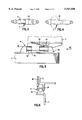
- FIG. 1 is a side view of transport container disposed on a chassis of a commercial vehicle according to a preferred embodiment of the present invention
- FIG. 2 is an enlarged perspective view of detail area II of FIG. 1 of one embodiment of a bearing between the transport container and the chassis;
- FIG. 3 is a view of one embodiment of a force-absorbing element of a bearing according to the present invention.
- FIG. 4 is a view of another embodiment of a force-absorbing element of a bearing according to the present invention.
- FIG. 5 is an enlarged perspective view of detail area II of FIG. 1 of another embodiment of a bearing between the transport container and the chassis;
- FIG. 6 is an end view taken in the direction of arrow VI of the bearing in FIG. 5.
- a driver's cab 2 is connected in front in the driving direction with a rigid chassis 1 of a commercial vehicle.
- a transport container 3 in the form of a flatbed body, is disposed on the chassis 1 by way of bearings 4.
- the bearings 4 are applied to the transport container 3 in the front and the rear, on the one hand, between abutments 5 on the chassis and, on the other hand, abutments 6 on the transport container 3.
- the bearings 4 have force-absorbing elements 7 arranged between the abutments 5 and the abutments 6.
- the abutments 6 of the transport container 3 are displaceably disposed in the driving direction on the chassis 1 via one bearing 8, respectively.
- the force-absorbing elements 7 have a form which is elongated in the driving direction of the vehicle.
- FIGS. 3 and 4 illustrate various embodiments of force-absorbing elements which can be used to absorb energy.
- such an element 7 consists of metal tubes 9 and 10 which can be telescopically pushed into one another and whose outside walls are connected with one another in one piece.
- the outside wall of the tube 10 is bent in a rolling and therefore force-consuming manner together with the inside tube 9.
- the energy absorption effect is created when the inside tube 9 is pushed into the outside tube 10.
- the whole respective tube cross-section is rolled, that is, bent forward and backward by 180° respectively.
- the deformation takes place in a known rolling manner, for example as shown in German patent document 1,172,558.
- the chain line in FIG. 3 shows a deformed state of the force-absorbing element 7.
- the center part 11 of the force-absorbing element 7 is made of a fiber-reinforced plastic material which can deform in an energy-consuming manner during a vehicle crash.
- Special embodiments of such so-called crash elements are known per se.
- the fiber-reinforced plastic material fibers and, for example, resin, as the binder, are destroyed, in which case the fibers are torn and the resin is ripped open.
- the chain line in FIG. 4 shows a deformed state of the force-absorbing element 7.
- the chassis-side abutments each consist of an elongated guiding element 12 in the form of a cylindrical rod which is aligned in the driving direction and which is, in each case, fixedly connected only on the front side by way of a cap 13 with the chassis 1.
- the abutments 6 of the transport container 3 are constructed as bearing lugs 14 which are longitudinally displaceably disposed on the guiding elements 12. In this case, the bearing lugs 14 are assigned with respect to the position to the caps 13 situated in the rear in the driving direction.
- the guiding element 12 is enclosed by a sleeve 15 made of a force-absorbing plastic material which may be a fiber-reinforced plastic.
- a force-absorbing plastic material which may be a fiber-reinforced plastic.
- the force-absorbing elements 7 according to the present invention advantageously have an energy-absorbing effect, which reduces damage to the vehicle involved in the rear impact and protects the occupants therein.
- an arrow A indicates the force which emanates from the accident obstacle when the commercial vehicle impacts on this obstacle.
- Arrow B in FIG. 2 indicates the direction in which the force-absorbing elements 7 deform and whereby a controlled limited displacement of the transport-container-side abutments 6 takes place in the direction of the abutments 5 stationarily remaining on the chassis.
- the bottom of a transport container 3 is relatively securely protected by way of the bearings 4 according to the invention against an uncontrolled impact onto the driver's cab 2 in the case of a collision.
- the upper area of the wall of the transport container 3 directly adjoining the driver's cab 2 is also protected with respect to the chassis 1 by way of one of the bearings 4 having a force-absorbing construction. This is achieved by means of a support which can be acted upon tensile stress and which may be in the form of a traction rope.
- This support 16 is mounted to the transport-container-side abutment 6 which is situated farthest to the rear in the driving direction. Such supports 16 are provided on each broadside of the transport container 3.
- the kinetic energy which is released during a collision by a cargo inside the transport container 3 is absorbed in the bearings 4 in such a manner that an uncontrolled, unreduced impact of the transport container 3 on the driver's cab 2 can be avoided.
- the safety of the crew of the driver's cab can be considerably increased in this manner in the case of a crash.
Landscapes
- Engineering & Computer Science (AREA)
- Mechanical Engineering (AREA)
- Transportation (AREA)
- Chemical & Material Sciences (AREA)
- Combustion & Propulsion (AREA)
- Vibration Dampers (AREA)
- Body Structure For Vehicles (AREA)
Abstract
Description
Claims (9)
Applications Claiming Priority (2)
| Application Number | Priority Date | Filing Date | Title |
|---|---|---|---|
| DE19617565 | 1996-05-02 | ||
| DE19617565A DE19617565C2 (en) | 1996-05-02 | 1996-05-02 | Commercial vehicle with a cab and a separate transport container |
Publications (1)
| Publication Number | Publication Date |
|---|---|
| US5947550A true US5947550A (en) | 1999-09-07 |
Family
ID=7793085
Family Applications (1)
| Application Number | Title | Priority Date | Filing Date |
|---|---|---|---|
| US08/850,741 Expired - Lifetime US5947550A (en) | 1996-05-02 | 1997-05-02 | Commercial vehicle having a driver's cab and a transport container separated therefrom |
Country Status (2)
| Country | Link |
|---|---|
| US (1) | US5947550A (en) |
| DE (1) | DE19617565C2 (en) |
Cited By (6)
| Publication number | Priority date | Publication date | Assignee | Title |
|---|---|---|---|---|
| US6241308B1 (en) * | 1999-09-20 | 2001-06-05 | Iap Intermodal, Llc | Passenger and freight carrying vehicle |
| US20060108818A1 (en) * | 2004-11-24 | 2006-05-25 | Blaine Carroll | Combination passenger and cargo carrier |
| US20060273624A1 (en) * | 2005-06-03 | 2006-12-07 | Romano Ronald J | Elevated deck bus with removable roof |
| US7703781B2 (en) | 2003-10-24 | 2010-04-27 | Aloha, Llc | Suspensions for low floor vehicle |
| US9010784B2 (en) | 2009-09-01 | 2015-04-21 | Parto Rezania | Suspension mechanism |
| CN111332371A (en) * | 2020-03-19 | 2020-06-26 | 泰州市佳洁环保科技有限公司 | High-safety damping environment-friendly foldable electric vehicle |
Families Citing this family (1)
| Publication number | Priority date | Publication date | Assignee | Title |
|---|---|---|---|---|
| US9776669B2 (en) * | 2014-02-26 | 2017-10-03 | GM Global Technology Operations LLC | Chassis mount structure |
Citations (19)
| Publication number | Priority date | Publication date | Assignee | Title |
|---|---|---|---|---|
| US2959446A (en) * | 1958-04-24 | 1960-11-08 | Thompson William Francis | Automobile crash absorbing construction |
| DE1172558B (en) * | 1959-08-12 | 1964-06-18 | Gen Motors Corp | Shock absorber, especially for motor vehicles |
| FR2147012A1 (en) * | 1971-07-29 | 1973-03-09 | Angelucci Marc | |
| US3831998A (en) * | 1972-03-13 | 1974-08-27 | H Hewitt | Automobile construction for safety of occupants |
| US3861736A (en) * | 1970-12-01 | 1975-01-21 | Daimler Benz Ag | Truck driver protection shield |
| US3955640A (en) * | 1974-08-23 | 1976-05-11 | Mitsubishi Jidosha Kogyo Kabushiki Kaisha | Absorbing safety arrangement for a truck |
| US3981530A (en) * | 1974-08-14 | 1976-09-21 | Mitsubishi Jidosha Kogyo Kabushiki Kaisha | Energy absorbing loading table mount |
| US3993352A (en) * | 1974-09-17 | 1976-11-23 | Mitsubishi Jidosha Kogyo Kabushiki Kaisha | Energy absorbing dump truck body |
| US4054314A (en) * | 1974-09-05 | 1977-10-18 | Mitsubishi Jidosha Kogyo Kabushiki Kaisha | Motor truck |
| JPS5336825A (en) * | 1977-09-30 | 1978-04-05 | Mitsubishi Motors Corp | Semi-trailer truck |
| US4175634A (en) * | 1976-04-19 | 1979-11-27 | Mitsubishi Jidosha Kogyo Kabushiki Kaisha | Truck with hydraulic means for absorbing impact energy |
| US4951999A (en) * | 1989-02-15 | 1990-08-28 | Pm Equipment Sales, Inc. | High lift dump truck |
| JPH02227382A (en) * | 1989-03-01 | 1990-09-10 | Hino Motors Ltd | Body supporting device for automobile |
| US4988081A (en) * | 1989-01-19 | 1991-01-29 | Boge Ag | Impact damper for a motor vehicle |
| US5174421A (en) * | 1989-09-09 | 1992-12-29 | Bayer Aktiengesellschaft | Damper in the form of a shock absorber |
| DE4241108A1 (en) * | 1991-12-16 | 1993-06-17 | Volkswagen Ag | Deformation element partic. for road vehicle - which works according to collar principle and in central deformation area is of non-reinforced thermoplastic material |
| US5293973A (en) * | 1991-12-16 | 1994-03-15 | Volkswagen Ag | Deformation member having an eversion portion |
| US5403113A (en) * | 1992-08-12 | 1995-04-04 | Energy Absorption Systems, Inc. | Shear loading energy absorbing device |
| US5588511A (en) * | 1995-05-15 | 1996-12-31 | Sargent & Lundy | Seismic pipe restraint and method for using the same |
Family Cites Families (1)
| Publication number | Priority date | Publication date | Assignee | Title |
|---|---|---|---|---|
| DE2462816C2 (en) * | 1974-10-18 | 1980-10-23 | Mitsubishi Jidosha Kogyo K.K., Tokio | Trucks |
-
1996
- 1996-05-02 DE DE19617565A patent/DE19617565C2/en not_active Expired - Fee Related
-
1997
- 1997-05-02 US US08/850,741 patent/US5947550A/en not_active Expired - Lifetime
Patent Citations (19)
| Publication number | Priority date | Publication date | Assignee | Title |
|---|---|---|---|---|
| US2959446A (en) * | 1958-04-24 | 1960-11-08 | Thompson William Francis | Automobile crash absorbing construction |
| DE1172558B (en) * | 1959-08-12 | 1964-06-18 | Gen Motors Corp | Shock absorber, especially for motor vehicles |
| US3861736A (en) * | 1970-12-01 | 1975-01-21 | Daimler Benz Ag | Truck driver protection shield |
| FR2147012A1 (en) * | 1971-07-29 | 1973-03-09 | Angelucci Marc | |
| US3831998A (en) * | 1972-03-13 | 1974-08-27 | H Hewitt | Automobile construction for safety of occupants |
| US3981530A (en) * | 1974-08-14 | 1976-09-21 | Mitsubishi Jidosha Kogyo Kabushiki Kaisha | Energy absorbing loading table mount |
| US3955640A (en) * | 1974-08-23 | 1976-05-11 | Mitsubishi Jidosha Kogyo Kabushiki Kaisha | Absorbing safety arrangement for a truck |
| US4054314A (en) * | 1974-09-05 | 1977-10-18 | Mitsubishi Jidosha Kogyo Kabushiki Kaisha | Motor truck |
| US3993352A (en) * | 1974-09-17 | 1976-11-23 | Mitsubishi Jidosha Kogyo Kabushiki Kaisha | Energy absorbing dump truck body |
| US4175634A (en) * | 1976-04-19 | 1979-11-27 | Mitsubishi Jidosha Kogyo Kabushiki Kaisha | Truck with hydraulic means for absorbing impact energy |
| JPS5336825A (en) * | 1977-09-30 | 1978-04-05 | Mitsubishi Motors Corp | Semi-trailer truck |
| US4988081A (en) * | 1989-01-19 | 1991-01-29 | Boge Ag | Impact damper for a motor vehicle |
| US4951999A (en) * | 1989-02-15 | 1990-08-28 | Pm Equipment Sales, Inc. | High lift dump truck |
| JPH02227382A (en) * | 1989-03-01 | 1990-09-10 | Hino Motors Ltd | Body supporting device for automobile |
| US5174421A (en) * | 1989-09-09 | 1992-12-29 | Bayer Aktiengesellschaft | Damper in the form of a shock absorber |
| DE4241108A1 (en) * | 1991-12-16 | 1993-06-17 | Volkswagen Ag | Deformation element partic. for road vehicle - which works according to collar principle and in central deformation area is of non-reinforced thermoplastic material |
| US5293973A (en) * | 1991-12-16 | 1994-03-15 | Volkswagen Ag | Deformation member having an eversion portion |
| US5403113A (en) * | 1992-08-12 | 1995-04-04 | Energy Absorption Systems, Inc. | Shear loading energy absorbing device |
| US5588511A (en) * | 1995-05-15 | 1996-12-31 | Sargent & Lundy | Seismic pipe restraint and method for using the same |
Cited By (9)
| Publication number | Priority date | Publication date | Assignee | Title |
|---|---|---|---|---|
| US6241308B1 (en) * | 1999-09-20 | 2001-06-05 | Iap Intermodal, Llc | Passenger and freight carrying vehicle |
| US6336676B2 (en) * | 1999-09-20 | 2002-01-08 | Iap Intermodal, Llc | Passenger and freight carrying vehicle |
| US7703781B2 (en) | 2003-10-24 | 2010-04-27 | Aloha, Llc | Suspensions for low floor vehicle |
| US20060108818A1 (en) * | 2004-11-24 | 2006-05-25 | Blaine Carroll | Combination passenger and cargo carrier |
| US7275901B2 (en) | 2004-11-24 | 2007-10-02 | Blaine Carroll | Combination passenger and cargo carrier |
| US20060273624A1 (en) * | 2005-06-03 | 2006-12-07 | Romano Ronald J | Elevated deck bus with removable roof |
| US20060273623A1 (en) * | 2005-06-03 | 2006-12-07 | Romano Ronald J | Open air elevated deck bus |
| US9010784B2 (en) | 2009-09-01 | 2015-04-21 | Parto Rezania | Suspension mechanism |
| CN111332371A (en) * | 2020-03-19 | 2020-06-26 | 泰州市佳洁环保科技有限公司 | High-safety damping environment-friendly foldable electric vehicle |
Also Published As
| Publication number | Publication date |
|---|---|
| DE19617565A1 (en) | 1997-11-13 |
| DE19617565C2 (en) | 2000-09-21 |
Similar Documents
| Publication | Publication Date | Title |
|---|---|---|
| US6672438B2 (en) | Crash box collision damper for motor vehicle | |
| US3743347A (en) | Safety chassis | |
| US9409601B2 (en) | Motor vehicle having an axle support | |
| JP5821334B2 (en) | Front underrun protector | |
| EP1930226B1 (en) | Front carriage of a train equipped with a front structure that absorbs energy in case of collision | |
| CN103029754A (en) | Vehicle rear structure | |
| CN110481477B (en) | Energy-absorbing structure and vehicle with same | |
| JP4518276B2 (en) | Driver cab support structure for commercial vehicles with safety cells | |
| US5947550A (en) | Commercial vehicle having a driver's cab and a transport container separated therefrom | |
| US5906248A (en) | Safety device for cab over type vehicle | |
| EP4114714B1 (en) | Vehicle with crash impact absorbing arrangement | |
| KR100916597B1 (en) | Stabilizer and tube-buffer with stabilizer for railway vehicle | |
| CN209870513U (en) | Vehicle with a steering wheel | |
| EP4108554B1 (en) | A cab-over engine truck | |
| CN110745089A (en) | A crashproof roof beam and vehicle for vehicle | |
| US12116040B2 (en) | Vehicle with crash impact absorbing arrangement | |
| CN210027325U (en) | Automobile aluminum alloy anti-collision beam assembly | |
| GB2503095A (en) | Double crash box between front bumper and vehicle frame | |
| CN220742958U (en) | Anti-collision buffer device for vehicle | |
| RU210796U1 (en) | UPGRADE VEHICLE | |
| CN213534636U (en) | Vehicle side protection device | |
| KR100440855B1 (en) | A bumper of automobile | |
| KR100482965B1 (en) | A bumper for vehicle | |
| KR890005280Y1 (en) | Automobile frame structure | |
| KR19980032872U (en) | Sequential Shock Absorption Structure of Vehicle Frame |
Legal Events
| Date | Code | Title | Description |
|---|---|---|---|
| FEPP | Fee payment procedure |
Free format text: PAYOR NUMBER ASSIGNED (ORIGINAL EVENT CODE: ASPN); ENTITY STATUS OF PATENT OWNER: LARGE ENTITY |
|
| AS | Assignment |
Owner name: DAIMLER-BENZ AG, GERMANY Free format text: ASSIGNMENT OF ASSIGNORS INTEREST;ASSIGNORS:MEHREN, HERBERT;NOHR, MATTHIAS;REEL/FRAME:008828/0150;SIGNING DATES FROM 19970428 TO 19970429 |
|
| STCF | Information on status: patent grant |
Free format text: PATENTED CASE |
|
| AS | Assignment |
Owner name: DAIMLERCHRYSLER AG, GERMANY Free format text: CHANGE OF NAME;ASSIGNOR:DAIMLER-BENZ AKTIENGESELLSCHAFT;REEL/FRAME:010281/0203 Effective date: 19990108 |
|
| FEPP | Fee payment procedure |
Free format text: PAYOR NUMBER ASSIGNED (ORIGINAL EVENT CODE: ASPN); ENTITY STATUS OF PATENT OWNER: LARGE ENTITY Free format text: PAYER NUMBER DE-ASSIGNED (ORIGINAL EVENT CODE: RMPN); ENTITY STATUS OF PATENT OWNER: LARGE ENTITY |
|
| FEPP | Fee payment procedure |
Free format text: PAYER NUMBER DE-ASSIGNED (ORIGINAL EVENT CODE: RMPN); ENTITY STATUS OF PATENT OWNER: LARGE ENTITY Free format text: PAYOR NUMBER ASSIGNED (ORIGINAL EVENT CODE: ASPN); ENTITY STATUS OF PATENT OWNER: LARGE ENTITY |
|
| FPAY | Fee payment |
Year of fee payment: 4 |
|
| REMI | Maintenance fee reminder mailed | ||
| FPAY | Fee payment |
Year of fee payment: 8 |
|
| AS | Assignment |
Owner name: DAIMLER AG, GERMANY Free format text: CHANGE OF NAME;ASSIGNOR:DAIMLERCHRYSLER AG;REEL/FRAME:020976/0889 Effective date: 20071019 Owner name: DAIMLER AG,GERMANY Free format text: CHANGE OF NAME;ASSIGNOR:DAIMLERCHRYSLER AG;REEL/FRAME:020976/0889 Effective date: 20071019 |
|
| FPAY | Fee payment |
Year of fee payment: 12 |
|
| AS | Assignment |
Owner name: DAIMLER AG, GERMANY Free format text: CORRECTIVE ASSIGNMENT TO CORRECT THE APPLICATION NO. 10/567,810 PREVIOUSLY RECORDED ON REEL 020976 FRAME 0889. ASSIGNOR(S) HEREBY CONFIRMS THE CHANGE OF NAME;ASSIGNOR:DAIMLERCHRYSLER AG;REEL/FRAME:053583/0493 Effective date: 20071019 |