US5927147A - Power sharing gear sets - Google Patents
Power sharing gear sets Download PDFInfo
- Publication number
- US5927147A US5927147A US09/167,760 US16776098A US5927147A US 5927147 A US5927147 A US 5927147A US 16776098 A US16776098 A US 16776098A US 5927147 A US5927147 A US 5927147A
- Authority
- US
- United States
- Prior art keywords
- helical
- driven
- drive
- gears
- shaft
- Prior art date
- Legal status (The legal status is an assumption and is not a legal conclusion. Google has not performed a legal analysis and makes no representation as to the accuracy of the status listed.)
- Expired - Lifetime
Links
- 230000005540 biological transmission Effects 0.000 claims abstract description 47
- 238000000926 separation method Methods 0.000 claims abstract description 13
- 230000004044 response Effects 0.000 claims description 9
- 238000000034 method Methods 0.000 claims 6
- 230000000452 restraining effect Effects 0.000 claims 4
- 230000007480 spreading Effects 0.000 description 17
- 238000004519 manufacturing process Methods 0.000 description 11
- 230000013011 mating Effects 0.000 description 7
- 230000007246 mechanism Effects 0.000 description 4
- 230000001154 acute effect Effects 0.000 description 3
- 230000008859 change Effects 0.000 description 2
- 230000001419 dependent effect Effects 0.000 description 1
- 238000010586 diagram Methods 0.000 description 1
- 230000003993 interaction Effects 0.000 description 1
- 238000012423 maintenance Methods 0.000 description 1
- 239000002184 metal Substances 0.000 description 1
- 230000004048 modification Effects 0.000 description 1
- 238000012986 modification Methods 0.000 description 1
- 230000002028 premature Effects 0.000 description 1
- 230000008439 repair process Effects 0.000 description 1
Images


Classifications
-
- F—MECHANICAL ENGINEERING; LIGHTING; HEATING; WEAPONS; BLASTING
- F16—ENGINEERING ELEMENTS AND UNITS; GENERAL MEASURES FOR PRODUCING AND MAINTAINING EFFECTIVE FUNCTIONING OF MACHINES OR INSTALLATIONS; THERMAL INSULATION IN GENERAL
- F16H—GEARING
- F16H1/00—Toothed gearings for conveying rotary motion
- F16H1/02—Toothed gearings for conveying rotary motion without gears having orbital motion
- F16H1/04—Toothed gearings for conveying rotary motion without gears having orbital motion involving only two intermeshing members
- F16H1/06—Toothed gearings for conveying rotary motion without gears having orbital motion involving only two intermeshing members with parallel axes
- F16H1/08—Toothed gearings for conveying rotary motion without gears having orbital motion involving only two intermeshing members with parallel axes the members having helical, herringbone, or like teeth
-
- Y—GENERAL TAGGING OF NEW TECHNOLOGICAL DEVELOPMENTS; GENERAL TAGGING OF CROSS-SECTIONAL TECHNOLOGIES SPANNING OVER SEVERAL SECTIONS OF THE IPC; TECHNICAL SUBJECTS COVERED BY FORMER USPC CROSS-REFERENCE ART COLLECTIONS [XRACs] AND DIGESTS
- Y10—TECHNICAL SUBJECTS COVERED BY FORMER USPC
- Y10T—TECHNICAL SUBJECTS COVERED BY FORMER US CLASSIFICATION
- Y10T74/00—Machine element or mechanism
- Y10T74/19—Gearing
- Y10T74/19628—Pressure distributing
Definitions
- the present invention is directed to improvements in load sharing amongst gears when multiple gears are mounted on a common shaft. More particularly, the present invention is directed to a gear transmission having pairs of helical gears mounted on a drive shaft for engagement with respective pairs of helical gears mounted on a driven shaft resulting in even load sharing amongst engaging gears.
- the present invention is directed to a gear transmission having pairs of helical gears mounted on a drive shaft engaging pairs of helical gears mounted on a parallel driven shaft. In operation, the present invention obtains even load sharing among engaging and mating gears during power transmission.
- the pairs of helical gears mounted for rotation on the drive shaft and the driven shaft are also mounted, by using for example spline shafts, for axial movement on the respective shafts. Retaining members on the respective shafts permit axial movement of the helical gears on the shafts but stop further axial movement at a selected position.
- the drive shaft is rotated in the counter-clockwise direction.
- the angle of the helical cut on the helical gear pairs mounted on the drive shaft has a hand on adjacent gear pairs such that adjacent gear pairs are pushed together in the axial direction due to axial thrust caused by counter-clockwise rotation.
- the angle of the helical cut on the helical gear pairs mounted on the driven shaft has a hand on adjacent gear pairs such that the adjacent driven shaft gear pairs separate and spread by movement of each gear in the gear pair in opposite axial directions due to axial thrust caused by mating with engaging drive gears.
- one pair of helical drive gears on the drive shaft will mate with a corresponding engaging helical gear pair on the driven shaft and establish axial thrust forces due to this mating prior to other helical gear pairs mating.
- the helical gear pairs mounted on the driven shaft have a helical cut such that the hand of the cut on adjacent pairs of gears will cause axial spreading of the gears due to axial thrust forces created upon mating with a counter-clockwise rotating engaging pair of gears on the drive shaft.
- this first pair of helical gears on the driven shaft which mate with a corresponding pair of helical gears on the drive shaft, start to spread with each gear in the gear pair moving axially on the driven shaft in opposite directions. Due to the spreading of this pair of gears on the driven shaft, there is no rotation of this pair of gears on the driven shaft and no loading of the drive shaft.
- the system is self balancing and there is even load sharing amongst all the gears.
- FIG. 1 is a schematic view of one embodiment of a transmission in accordance with the present invention illustrating pairs of helical gears on a drive shaft and pairs of helical gears on a driven shaft prior to commencement of rotation of the drive shaft;
- FIG. 2 is a schematic view of the embodiment of the present invention illustrated in FIG. 1 wherein rotation of the drive shaft has just commenced, and some, but not all, of the pairs of helical gears on the driven shaft have mated with corresponding pairs of helical gears on the drive shaft and started separation in the axial direction of the driven shaft (distance of separation greatly exaggerated), this being prior to loading of gears on the driven shaft with resulting rotation of the driven shaft;
- FIG. 3 is a schematic view of the embodiment of the present invention illustrated in FIG. 1 wherein rotation of the drive shaft has proceeded to where all corresponding pairs of helical gears on both drive and driven shafts are mated to cause all pairs of helical gears on the driven shaft to be separated in the axial direction of the driven shaft at a distance (distance of separation greatly exaggerated) resulting in even loading of the gears and rotation of the driven shaft;
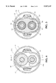
- FIG. 4 is a schematic cross-sectional view along line 4--4 of FIG. 1 with an inner and outer casing added;
- FIG. 5 is a schematic cross-sectional view along line 5--5 of FIG. 1 with an inner and outer casing added and a bearing housing added;
- FIG. 6 is a vector force diagram illustrating the forces acting on a set of paired helical gears at the start of counter-clockwise rotation of the drive shaft, all in accordance with one embodiment of the present invention.
- FIG. 7 is a schematic cross-sectional view along line 7--7 of FIG. 4.
- FIG. 1 schematically illustrates one embodiment of a paired helical gear transmission in accordance with the present invention.
- a drive shaft 22 having a first end 10 and a second end 11.
- Second end 11 of drive shaft 22 would be adapted for connection to a drive mechanism (not illustrated) for rotating drive shaft 22.
- driven shaft 35 Located parallel to drive shaft 22 is driven shaft 35 having a first end 12 and a second end 13.
- First end 12 of driven shaft 35 would be adapted for connection to an output mechanism (not illustrated) for receiving output rotation and power.
- paired helical gears 24, 26 and 28 are also mounted on drive shaft 22 for axial movement on drive shaft 22 in the axial direction of drive shaft 22. Preferred mounting mechanisms will herein after be discussed.
- Each paired helical gear 24, 26 and 28 on drive shaft 22 comprises a first gear half 31a, 31b and 31c, respectively, on the side of the first end 10 of drive shaft 22 and a second gear half 33a, 33b and 33c, respectively, on the side of the second end 11 of drive shaft 22.
- paired helical gears 42, 39 and 37 Mounted for rotation on driven shaft 35 are paired helical gears 42, 39 and 37. Paired helical gears 42, 39 and 37 are also mounted on driven shaft 35 for axial movement on driven shaft 35 in the axial direction of driven shaft 35.
- Each paired helical gear 42, 39 and 37 mounted on driven shaft 35 comprises a first gear half 44a, 44b and 44c, respectively, on the side of first end 12 of the driven shaft 35 and a second gear half 46a, 46b and 46c, respectively, on the side of second end 13 of driven shaft 35.
- Paired helical drive gear 24 engaging paired helical driven gear 42 forms a first paired helical gear set 51.
- Paired helical drive gear 26 engaging paired helical driven gear 39 forms a second paired helical gear set 53.
- Paired helical drive gear 28 and paired helical driven gear 37 forms a third paired helical gear set. It will be understood that the illustration of three paired helical gear sets in the embodiment of FIGS. 1-3 of the drawings is by way of illustrative example and not by way of limitation. The actual number of paired helical gear sets employed by one skilled in the art would be determined by the design requirements of the intended application.
- drive gear pair 31a and 33a each have a helical cut at the same angle, but in the opposite sense to one another, which results in the thrust of gear half 31a and gear half 33a to be directed inward pushing gear half 31a and gear half 33a tightly together when drive shaft 22 is rotated in the counter-clockwise direction.
- driven gear pair 44a, 46a each have a helical cut at the same angle, but in the opposite sense to one another, which results in the thrust of gear half 44a and gear half 46a to be directed outward causing gear half 44a and gear half 46a to separate in the axial direction of driven shaft 35 when drive shaft 22 rotates in the counter-clockwise direction for causing driven shaft 35 to rotate in the clockwise direction.
- the helical cut of drive gear 31a is at the same angle but in the opposite sense to the helical cut of driven gear 44a.
- the helical cut of drive gear 33a is at the same angle but in the opposite sense to the helical cut of driven gear 46a.
- drive shaft 22 could be rotated in the clockwise direction establishing forces which cause drive gears 31a and 33a to separate in the axial direction of the drive shaft 22 and driven gears 44a and 46a to be pushed together in the axial direction of the driven shaft. It will be apparent to one skilled in the art, with reference to FIG. 6, that the sense or the hand of the helical cut of all of gears 31a, 33a, 44a and 46a illustrated could be reversed or made opposite and the described principles of operation, in accordance with the present invention, would apply.
- the angle of the helical cut with respect to the axial centerline of the respective drive shaft or driven shaft for each helical gear of each paired helical gear set will be the same, with the sense or the hand of the angle of the helical cut varying as previously described.
- the helical cut of gear half 33a is at an acute angle with respect to the axis of drive shaft 22 when the angle is measured counter-clockwise from the axis of drive shaft 22 to the helical cut of gear half 33a.
- the helical cut of gear half 31a is at an acute angle with respect to the axis of drive shaft 22 when the angle is measured clockwise from the axis of drive shaft 22 to the helical cut of gear half 31a.
- the acute angles of the helical cut of gear half 31a and gear half 33a are equal but are in the opposite hand or in the opposite sense. As can be seen in drawings, this description applies to the other pairs of helical gears illustrated.
- the diameter of the helical gears on the drive shaft 22 is larger than the diameter of the helical gears on the driven shaft 35.
- the embodiment of the present invention illustrated in the drawings is a step up transmission.
- the diameter of the helical gears on the drive shaft may be smaller than the diameter of the helical gears on the driven shaft, with this embodiment of the present invention (not illustrated) being a step down transmission.
- the diameter of all helical gears mounted on the drive shaft is the same and the diameter of all helical gears mounted on the driven shaft is the same.
- FIG. 4 is a cross-section at 4--4 of FIG. 1 with inner housing 70 and outer housing 71 added.
- FIG. 4 shows drive shaft 22 being a spline shaft having teeth 49 engaging corresponding notches in helical drive gear 31a.
- driven shaft 35 is a spline shaft having teeth 48 engaging corresponding notches in helical driven gear 44a.
- the spline shaft mounting results in the transmission of rotational movement and power between respective gears and shafts.
- the spline shaft mounting also permits axial movement of the gears on their respective shafts.
- spline shaft is by way of example and not limitation.
- Other mechanisms may be selected by one skilled in the art to mount the helical gears to their respective shafts for both rotation and axial movement, such as being keyed rather than splined.
- each paired helical gear has a cylindrical flange bearing member 62 mounted thereto.
- the bearing housing has been removed. That is, helical gear half 31a, 31b and 31c each have a cylindrical flange bearing member 62 mounted on their respective outer face perpendicular to the axis of drive shaft 22 facing first end 10 of drive shaft 22.
- Helical gear half 33a, 33b and 33c each have a cylindrical flange bearing member 62 mounted on their respective outer face perpendicular to the axis of drive shaft 22 facing second end 11 of drive shaft 22.
- Helical gear half 44a, 44b and 44c each have a cylindrical flange bearing member 62 mounted on their respective outer face perpendicular to the axis of driven shaft 35 facing first end 12 of driven shaft 35.
- Helical gear half 46a, 46b and 46c each have a cylindrical flange bearing member 62 mounted on their respective outer face perpendicular to axis of driven shaft 35 facing second end 13 of driven shaft 35.
- FIG. 5 is a cross-sectional view along line 5--5 of FIG. 1 with bearing housing 65 added.
- bearing members 62 are splined respectively to drive shaft 22 and driven shaft 35.
- the outer cylindrical surface 64 of bearing member 62 is a bearing race for bearings 66. It will be appreciated that bearing wall 65 supports bearing members 62 and maintains the alignment of drive shaft 22 and driven shaft 35.
- retaining ring 57a located near the first end 10 of drive shaft 22 is retaining ring 57a and located near the second end 11 of drive shaft 22 is retaining ring 57b.
- retaining ring 59a located near the first end 12 of driven shaft 35 is retaining ring 59a and located near the second end 13 of driven shaft 35 is retaining ring 59b.
- the retaining rings 57a, 57b, 59a, 59b are mounted to their respective shafts so that they cannot move in the axial direction of their respective shafts.
- Retaining rings 57a and 57b on drive shaft 22 retain or stop axial movement of the drive helical gears on drive shaft 22.
- Retaining rings 59a and 59b on driven shaft 35 retain or stop axial movement of the driven helical gears on driven shaft 35.
- the function of the retaining rings will be more fully hereinafter explained.
- Drive shaft 22 and driven shaft 35 are mounted (not illustrated) so that they do not move in their respective axial directions in response to forces established by rotation of the respective shafts and rotation of the respective helical gears.
- FIG. 1 illustrates the embodiment of the present invention using three sets of paired helical gears prior to the start of rotation of drive shaft 22.
- one set of paired of helical gears say, for example, 24, 42, will mate first.
- the thrusts previously explained in connection with FIG. 6, will cause driven helical gears 44a and 46a to begin to separate.
- Drive helical gears 31a and 33a will be pushed together. This allows drive shaft 22 to further rotate without loading or rotating the driven gears.
- one or more addition set of paired helical gears will mate, say for example, 28, 37, and the driven helical gears 44c and 46c will begin to separate.
- Drive helical gears 31c and 33c will be pushed together. This is illustrated in FIG. 2 of the drawings where driven helical gears 44a and 46a of paired helical gear set 24, 42 have begun to separate in the axial direction of driven shaft 35 and where driven helical gears 44c and 46c of paired helical gear set 28, 37 have begun to separate in the axial direction of driven shaft 35.
- Manufacturing tolerances will continue to permit rotation of the drive shaft 22 without loading of the drive shaft and rotation of the driven shaft 35 due to the continued spreading of the pairs of driven helical gears of the helical gear sets until such time that the retaining rings 59a, 59b on driven shaft 35 stop axial spreading of the driven helical gear pairs and the bearing members 62 of adjacent driven helical gear halfs are in abutment.
- This is illustrated in FIG. 3.
- the design permits the drive shaft 22 to continue to rotate in the unloaded condition until all the helical gear sets mate and spreading of all the driven helical gear pairs starts in the axial direction of the driven shaft without loading and rotation of the driven shaft.
- retaining rings 59a and 59b are located on the driven shaft 35 to provide sufficient axial play or axial distance so that the driven helical gear pairs of all helical gear sets have begun to separate in the axial direction of driven shaft 35 prior to bearing number 62 of driven gear 44a being abutted with force against retaining ring 59a and bearing member 62 of driven gear 46c being abutted with force against retaining ring 59b.
- retaining rings 59a and 59b prevent any further total axial spreading of the driven helical gears, loading of drive shaft 22 and rotation of driven shaft 35 begin. The distance of the spreading between gear halfs of the paired driven helical gears still can change relative to one another to balance load, hereinafter more fully discussed.
- FIG. 3 illustrates the spreading of all pairs of driven gears 44a and 46a, 44b and 46b, and 44c and 46c in the axial direction of driven shaft 35 with axial spreading being stopped by retaining rings 59a and 59b. That is, in FIG. 3, bearing member 62 of gear half 44a abuts retaining ring 59a; bearing member 62 of gear half 46a abuts bearing member 62 of gear half 44b; bearing member 62 of gear half 46b abuts bearing member 62 of gear half 44c and bearing member 62 of gear half 46c abuts retaining ring 59b.
- any imbalance in the load results in a thrust imbalance between the driven gear pairs, That is, the driven gear pair which is experiencing a heavier load will start spreading further. Since the retaining rings or restraints will not allow any additional total axial spreading of the gears on the driven shaft, the spreading of the heavier loaded helical pair of driven gears causes other pairs of driven helical gears on the driven shaft to be pushed toward one another reducing their axial separation, which increases their load share and thereby rebalances the load. Since all the gears on the driven shaft are allowed to move freely and interact with one another, there is a net thrust from only the gear half at each end of the driven shaft. The thrust of the other gears is balanced by the opposite thrust of adjacent gears.
- the drive shaft helical gear halfs must be free to move axially on the drive shaft.
- the counter-clockwise rotation of drive shaft 22 results in the drive helical gear pairs 31a and 33a, 31b and 33b, and 31c and 33c to be pushed tightly together in the axial direction of the drive shaft 22.
- the drive side helical gear pairs must be free to move axially on the drive shaft 22. Due to differences in manufacturing tolerances, the driven helical gear pairs on the driven shaft do not spread equally in the axial direction. This uneven spacing of the driven helical gear pairs results in an unbalanced load on one side or the other of the drive side pairs which causes the drive side pairs to move axially along the drive shaft to "center" themselves with respect to the corresponding driven side pair to achieve a balanced load.
- the retaining rings 59a, 59b must permit for sufficient play or axial movement of the helical gear pairs on the driven shaft 35 so that all helical gear pairs mounted on the driven shaft 35 spread prior to retaining rings 59a, 59b preventing additional axial spreading and thus load being transmitted from the drive shaft 22 to the driven shaft 35.
- the distance of axial spreading of the driven helical gear pairs illustrated in FIGS. 2 and 3 is greatly exaggerated for purposes of clear description of the present invention.
- the axial spreading of the helical gear pairs on the driven shaft of the illustrative embodiment will be on the order of a few thousandths of an inch or on the order of a thousandth of a millimeter.
- FIGS. 1 to 3 uses three sets of paired helical gears.
- the number of sets of paired helical gears selected would be dependent upon the design criteria for a specific application.
- the diameters of the gears on the drive and driven shaft may be selected to provide either a step up or step down transmission.
- the drive shaft of the embodiment of FIGS. 1-3 may be rotated in the clockwise direction.
- helical gear halfs 31a, 33a could be machined from a common piece of metal because helical gear halfs 31a, 33a in this specific illustrative embodiment do not separate with respect to one another in the axial direction of the drive shaft.
- the present invention provides for a commercially practical, cost-effective gear transmission having multiple gears on a common drive shaft and a common driven shaft.
- the gears used in the present invention need only have commercially practical, cost-effective manufacturing tolerances.
Landscapes
- Engineering & Computer Science (AREA)
- General Engineering & Computer Science (AREA)
- Mechanical Engineering (AREA)
- Gear Transmission (AREA)
Priority Applications (14)
| Application Number | Priority Date | Filing Date | Title |
|---|---|---|---|
| US09/167,760 US5927147A (en) | 1998-02-09 | 1998-10-07 | Power sharing gear sets |
| CA002339242A CA2339242C (fr) | 1998-02-09 | 1999-02-02 | Ameliorations apportees a des ensembles d'engrenages a puissance partagee |
| EP99905678A EP1053413B1 (fr) | 1998-02-09 | 1999-02-02 | Ameliorations apportees a des ensembles d'engrenages a puissance partagee |
| AU25785/99A AU2578599A (en) | 1998-02-09 | 1999-02-02 | Improvements in power sharing gear sets |
| ES99905678T ES2323297T3 (es) | 1998-02-09 | 1999-02-02 | Mejoras en conjuntos de engranaje con energia repartida. |
| IL13821799A IL138217A (en) | 1998-02-09 | 1999-02-02 | Power supply relays |
| AT99905678T ATE427436T1 (de) | 1998-02-09 | 1999-02-02 | Verbesserungen zu radersatzen mit leistungsverteilung |
| DE69940663T DE69940663D1 (de) | 1998-02-09 | 1999-02-02 | Verbesserungen zu rädersätzen mit leistungsverteilung |
| CN99804840.2A CN1103005C (zh) | 1998-02-09 | 1999-02-02 | 改进了载荷分配的齿轮传动装置 |
| PCT/US1999/002313 WO1999040343A1 (fr) | 1998-02-09 | 1999-02-02 | Ameliorations apportees a des ensembles d'engrenages a puissance partagee |
| IDW20001731A ID27039A (id) | 1998-02-09 | 1999-02-02 | Peningkatan pada perangkat roda gigi pembagi tenaga |
| MXPA00008797A MXPA00008797A (es) | 1998-02-09 | 1999-02-02 | Mejoras en tren de engranajes que comparten energia. |
| DK99905678T DK1053413T3 (da) | 1998-02-09 | 1999-02-02 | Forbedringer i kraftfordelende tandhjulssæt |
| ARP990100527A AR014552A1 (es) | 1998-02-09 | 1999-02-08 | Transmision de engranajes |
Applications Claiming Priority (2)
| Application Number | Priority Date | Filing Date | Title |
|---|---|---|---|
| US2162298A | 1998-02-09 | 1998-02-09 | |
| US09/167,760 US5927147A (en) | 1998-02-09 | 1998-10-07 | Power sharing gear sets |
Related Parent Applications (1)
| Application Number | Title | Priority Date | Filing Date |
|---|---|---|---|
| US2162298A Continuation | 1998-02-09 | 1998-02-09 |
Publications (1)
| Publication Number | Publication Date |
|---|---|
| US5927147A true US5927147A (en) | 1999-07-27 |
Family
ID=26694912
Family Applications (1)
| Application Number | Title | Priority Date | Filing Date |
|---|---|---|---|
| US09/167,760 Expired - Lifetime US5927147A (en) | 1998-02-09 | 1998-10-07 | Power sharing gear sets |
Country Status (14)
| Country | Link |
|---|---|
| US (1) | US5927147A (fr) |
| EP (1) | EP1053413B1 (fr) |
| CN (1) | CN1103005C (fr) |
| AR (1) | AR014552A1 (fr) |
| AT (1) | ATE427436T1 (fr) |
| AU (1) | AU2578599A (fr) |
| CA (1) | CA2339242C (fr) |
| DE (1) | DE69940663D1 (fr) |
| DK (1) | DK1053413T3 (fr) |
| ES (1) | ES2323297T3 (fr) |
| ID (1) | ID27039A (fr) |
| IL (1) | IL138217A (fr) |
| MX (1) | MXPA00008797A (fr) |
| WO (1) | WO1999040343A1 (fr) |
Cited By (13)
| Publication number | Priority date | Publication date | Assignee | Title |
|---|---|---|---|---|
| US6117036A (en) * | 1999-07-29 | 2000-09-12 | New Venture Gear, Inc. | Split helical planetary gear assembly |
| US6334368B1 (en) * | 2000-05-17 | 2002-01-01 | Harrier Technologies, Inc. | Multi-path gear sets with load sharing between paths |
| US6374689B1 (en) * | 2000-05-22 | 2002-04-23 | Harrier Technologies, Inc. | Continuous load balancing gear sets |
| WO2011096919A1 (fr) | 2010-02-02 | 2011-08-11 | Harrier Technologies, Inc. | Perfectionnement à des jeux d'engrenages hélicoïdaux |
| US20110314940A1 (en) * | 2010-06-24 | 2011-12-29 | William Bruce Morrow | Spur gear power sharing gear sets |
| WO2011163494A1 (fr) * | 2010-06-24 | 2011-12-29 | Harrier Technologies Inc. | Système de transmission à courroie/chaîne |
| US20120180587A1 (en) * | 2011-01-18 | 2012-07-19 | William Bruce Morrow | Multi stage system for modular transmissions |
| US20130042709A1 (en) * | 2011-08-19 | 2013-02-21 | Jianwen Li | Gear Change Transmission Having Axially Adjusting Countershafts |
| US20130186223A1 (en) * | 2010-10-13 | 2013-07-25 | Autoinvent Transip Ab | Stationary gear unit |
| US20140290966A1 (en) * | 2013-03-27 | 2014-10-02 | William Bruce Morrow | Torsional Restraints For Downhole Transmissions |
| DE102013213122B3 (de) * | 2013-07-04 | 2015-01-08 | Sumitomo (Shi) Cyclo Drive Germany Gmbh | Getriebesystem |
| US20150114153A1 (en) * | 2012-06-25 | 2015-04-30 | Volvo Lastvagnar Ab | Gear arrangement and dual-clutch transmission provided therewith |
| JP2019082205A (ja) * | 2017-10-30 | 2019-05-30 | トヨタ自動車株式会社 | 動力伝達機構 |
Families Citing this family (3)
| Publication number | Priority date | Publication date | Assignee | Title |
|---|---|---|---|---|
| US6440197B1 (en) | 1999-07-27 | 2002-08-27 | G.B.D. Corp. | Apparatus and method separating particles from a cyclonic fluid flow including an apertured particle separation member within a cyclonic flow region |
| GB2471512A (en) * | 2009-07-03 | 2011-01-05 | Smart Mfg Technology Ltd | Gear set with helical gears which move axially to reduce imbalanced loads |
| CN103629305A (zh) * | 2013-12-06 | 2014-03-12 | 中石化石油工程机械有限公司第四机械厂 | 人字齿行星齿轮箱 |
Citations (7)
| Publication number | Priority date | Publication date | Assignee | Title |
|---|---|---|---|---|
| US1070589A (en) * | 1910-10-01 | 1913-08-19 | Georg Duffing | Reduction-gearing. |
| US1273556A (en) * | 1916-11-06 | 1918-07-23 | Fore River Ship Building Corp | Gearing. |
| US1320459A (en) * | 1916-07-31 | 1919-11-04 | George Edwards | Gear-and-pinion transmission. |
| US1479157A (en) * | 1921-12-20 | 1924-01-01 | Westinghouse Gear And Dynamome | Bearing for gearing |
| US3545296A (en) * | 1967-12-30 | 1970-12-08 | Dominion Eng Works Ltd | Variable gear tooth contact arrangement |
| US4612816A (en) * | 1983-10-28 | 1986-09-23 | Lazar Chalik | Gear assembly |
| US4641543A (en) * | 1984-10-12 | 1987-02-10 | Jessup Thurman W | Intermediate shaft thrust balance |
Family Cites Families (3)
| Publication number | Priority date | Publication date | Assignee | Title |
|---|---|---|---|---|
| DE1775782B1 (de) * | 1968-09-23 | 1971-10-07 | Weber Heinz Dipl Ing | Zahnradgetriebe mit einer eingangswelle und zwei parallelen eng zueinander angeordneten ausgangswellen mit lastausgleich |
| US6189397B1 (en) * | 1998-11-06 | 2001-02-20 | Harrier Technologies, Inc. | Multi-speed automotive transmission using paired helical gearing |
| JP2000213631A (ja) * | 1999-01-26 | 2000-08-02 | Fukuoka Joho System Kk | バックラッシュレスツインギア |
-
1998
- 1998-10-07 US US09/167,760 patent/US5927147A/en not_active Expired - Lifetime
-
1999
- 1999-02-02 AT AT99905678T patent/ATE427436T1/de active
- 1999-02-02 CN CN99804840.2A patent/CN1103005C/zh not_active Expired - Fee Related
- 1999-02-02 DK DK99905678T patent/DK1053413T3/da active
- 1999-02-02 ID IDW20001731A patent/ID27039A/id unknown
- 1999-02-02 AU AU25785/99A patent/AU2578599A/en not_active Abandoned
- 1999-02-02 EP EP99905678A patent/EP1053413B1/fr not_active Expired - Lifetime
- 1999-02-02 WO PCT/US1999/002313 patent/WO1999040343A1/fr active Application Filing
- 1999-02-02 CA CA002339242A patent/CA2339242C/fr not_active Expired - Fee Related
- 1999-02-02 DE DE69940663T patent/DE69940663D1/de not_active Expired - Lifetime
- 1999-02-02 IL IL13821799A patent/IL138217A/en not_active IP Right Cessation
- 1999-02-02 ES ES99905678T patent/ES2323297T3/es not_active Expired - Lifetime
- 1999-02-02 MX MXPA00008797A patent/MXPA00008797A/es active IP Right Grant
- 1999-02-08 AR ARP990100527A patent/AR014552A1/es active IP Right Grant
Patent Citations (7)
| Publication number | Priority date | Publication date | Assignee | Title |
|---|---|---|---|---|
| US1070589A (en) * | 1910-10-01 | 1913-08-19 | Georg Duffing | Reduction-gearing. |
| US1320459A (en) * | 1916-07-31 | 1919-11-04 | George Edwards | Gear-and-pinion transmission. |
| US1273556A (en) * | 1916-11-06 | 1918-07-23 | Fore River Ship Building Corp | Gearing. |
| US1479157A (en) * | 1921-12-20 | 1924-01-01 | Westinghouse Gear And Dynamome | Bearing for gearing |
| US3545296A (en) * | 1967-12-30 | 1970-12-08 | Dominion Eng Works Ltd | Variable gear tooth contact arrangement |
| US4612816A (en) * | 1983-10-28 | 1986-09-23 | Lazar Chalik | Gear assembly |
| US4641543A (en) * | 1984-10-12 | 1987-02-10 | Jessup Thurman W | Intermediate shaft thrust balance |
Cited By (18)
| Publication number | Priority date | Publication date | Assignee | Title |
|---|---|---|---|---|
| US6402654B1 (en) | 1999-07-29 | 2002-06-11 | New Venture Gear, Inc. | Compact multi-speed automatic transmission with load sharing and anti-phase gear assembly |
| US6117036A (en) * | 1999-07-29 | 2000-09-12 | New Venture Gear, Inc. | Split helical planetary gear assembly |
| US6334368B1 (en) * | 2000-05-17 | 2002-01-01 | Harrier Technologies, Inc. | Multi-path gear sets with load sharing between paths |
| US6374689B1 (en) * | 2000-05-22 | 2002-04-23 | Harrier Technologies, Inc. | Continuous load balancing gear sets |
| WO2011096919A1 (fr) | 2010-02-02 | 2011-08-11 | Harrier Technologies, Inc. | Perfectionnement à des jeux d'engrenages hélicoïdaux |
| US20110314940A1 (en) * | 2010-06-24 | 2011-12-29 | William Bruce Morrow | Spur gear power sharing gear sets |
| WO2011163494A1 (fr) * | 2010-06-24 | 2011-12-29 | Harrier Technologies Inc. | Système de transmission à courroie/chaîne |
| US8776639B2 (en) * | 2010-06-24 | 2014-07-15 | Harrier Technologies Inc. | Spur gear power sharing gear sets |
| US9512899B2 (en) * | 2010-10-13 | 2016-12-06 | Autoinvent Transip Ab | Stationary gear unit |
| US20130186223A1 (en) * | 2010-10-13 | 2013-07-25 | Autoinvent Transip Ab | Stationary gear unit |
| US20120180587A1 (en) * | 2011-01-18 | 2012-07-19 | William Bruce Morrow | Multi stage system for modular transmissions |
| US20130042709A1 (en) * | 2011-08-19 | 2013-02-21 | Jianwen Li | Gear Change Transmission Having Axially Adjusting Countershafts |
| US9234567B2 (en) * | 2011-08-19 | 2016-01-12 | Jianwen Li | Gear change transmission having axially adjusting countershafts |
| US20150114153A1 (en) * | 2012-06-25 | 2015-04-30 | Volvo Lastvagnar Ab | Gear arrangement and dual-clutch transmission provided therewith |
| US9593744B2 (en) * | 2012-06-25 | 2017-03-14 | Volve Lastvagnar AB | Gear arrangement and dual-clutch transmission provided therewith |
| US20140290966A1 (en) * | 2013-03-27 | 2014-10-02 | William Bruce Morrow | Torsional Restraints For Downhole Transmissions |
| DE102013213122B3 (de) * | 2013-07-04 | 2015-01-08 | Sumitomo (Shi) Cyclo Drive Germany Gmbh | Getriebesystem |
| JP2019082205A (ja) * | 2017-10-30 | 2019-05-30 | トヨタ自動車株式会社 | 動力伝達機構 |
Also Published As
| Publication number | Publication date |
|---|---|
| IL138217A (en) | 2004-06-20 |
| ES2323297T3 (es) | 2009-07-10 |
| WO1999040343A1 (fr) | 1999-08-12 |
| ATE427436T1 (de) | 2009-04-15 |
| IL138217A0 (en) | 2001-10-31 |
| DK1053413T3 (da) | 2009-07-20 |
| CN1296556A (zh) | 2001-05-23 |
| AU2578599A (en) | 1999-08-23 |
| CA2339242A1 (fr) | 1999-08-12 |
| AR014552A1 (es) | 2001-02-28 |
| CN1103005C (zh) | 2003-03-12 |
| DE69940663D1 (de) | 2009-05-14 |
| CA2339242C (fr) | 2008-09-16 |
| EP1053413A1 (fr) | 2000-11-22 |
| MXPA00008797A (es) | 2003-07-14 |
| EP1053413B1 (fr) | 2009-04-01 |
| ID27039A (id) | 2001-02-22 |
| EP1053413A4 (fr) | 2007-05-23 |
Similar Documents
| Publication | Publication Date | Title |
|---|---|---|
| US5927147A (en) | Power sharing gear sets | |
| KR0126648B1 (ko) | 연결장치 | |
| EP0698748A1 (fr) | Synchronisateur pour transmission | |
| US5733217A (en) | Centrifugal friction clutch for automatic speed changing device | |
| EP0309295B1 (fr) | Transmission à plusieurs contre-arbres | |
| US20180298957A1 (en) | Shifting Element for an Automatic Transmission | |
| US4034620A (en) | Gear retainer | |
| US5845754A (en) | Shift synchronizer for two speed transfer case and the like | |
| EP0418295B1 (fr) | Transmission variable en continu | |
| KR0185772B1 (ko) | 무단변속기 | |
| CA2379240C (fr) | Train d'engrenages a repartition de puissance dans une transmission planetaire | |
| US6513402B1 (en) | Multi-speed automotive transmission using paired helical gearing | |
| US4638687A (en) | Continuously-variable-ratio transmission having a single input member | |
| EP0390368B1 (fr) | Fixation des pignons sur l'arbre principal d'une boîte de vitesses | |
| US5562560A (en) | Speed reducing apparatus having wobbling rotation plate | |
| US6375595B1 (en) | Toroidal type continuously variable transmission | |
| US20110319208A1 (en) | Belt/chain drive system | |
| KR900001636B1 (ko) | 마찰구동식 무단 변속기어를 구성하기 위한 어셈블리 | |
| EP0090531A2 (fr) | Moyen de retenue pour engrenage | |
| US6024197A (en) | Support structure for clutch hub | |
| US6338691B1 (en) | Gearing for power sharing in planetary transmission | |
| US8776639B2 (en) | Spur gear power sharing gear sets | |
| US3712434A (en) | Synchronizing flexible coupling | |
| JP2022553911A (ja) | カップリング | |
| US5179866A (en) | Transmission gear retainer |
Legal Events
| Date | Code | Title | Description |
|---|---|---|---|
| AS | Assignment |
Owner name: HARRIER TECHNOLOGIES, INC., CONNECTICUT Free format text: ASSIGNMENT OF ASSIGNORS INTEREST;ASSIGNOR:MORROW, WILLIAM BRUCE;REEL/FRAME:009515/0204 Effective date: 19981005 |
|
| STCF | Information on status: patent grant |
Free format text: PATENTED CASE |
|
| FPAY | Fee payment |
Year of fee payment: 4 |
|
| FEPP | Fee payment procedure |
Free format text: PAT HOLDER CLAIMS SMALL ENTITY STATUS, ENTITY STATUS SET TO SMALL (ORIGINAL EVENT CODE: LTOS); ENTITY STATUS OF PATENT OWNER: SMALL ENTITY |
|
| REFU | Refund |
Free format text: REFUND - PAYMENT OF MAINTENANCE FEE, 8TH YEAR, LARGE ENTITY (ORIGINAL EVENT CODE: R1552); ENTITY STATUS OF PATENT OWNER: SMALL ENTITY |
|
| FPAY | Fee payment |
Year of fee payment: 8 |
|
| FEPP | Fee payment procedure |
Free format text: ENTITY STATUS SET TO SMALL (ORIGINAL EVENT CODE: SMAL); ENTITY STATUS OF PATENT OWNER: SMALL ENTITY |
|
| FPAY | Fee payment |
Year of fee payment: 12 |