US5901870A - Pilferproof cover and a container associated therewith - Google Patents
Pilferproof cover and a container associated therewith Download PDFInfo
- Publication number
- US5901870A US5901870A US08/891,054 US89105497A US5901870A US 5901870 A US5901870 A US 5901870A US 89105497 A US89105497 A US 89105497A US 5901870 A US5901870 A US 5901870A
- Authority
- US
- United States
- Prior art keywords
- safety ring
- container
- cover
- curvature
- radius
- Prior art date
- Legal status (The legal status is an assumption and is not a legal conclusion. Google has not performed a legal analysis and makes no representation as to the accuracy of the status listed.)
- Expired - Fee Related
Links
Images


Classifications
-
- B—PERFORMING OPERATIONS; TRANSPORTING
- B65—CONVEYING; PACKING; STORING; HANDLING THIN OR FILAMENTARY MATERIAL
- B65D—CONTAINERS FOR STORAGE OR TRANSPORT OF ARTICLES OR MATERIALS, e.g. BAGS, BARRELS, BOTTLES, BOXES, CANS, CARTONS, CRATES, DRUMS, JARS, TANKS, HOPPERS, FORWARDING CONTAINERS; ACCESSORIES, CLOSURES, OR FITTINGS THEREFOR; PACKAGING ELEMENTS; PACKAGES
- B65D55/00—Accessories for container closures not otherwise provided for
- B65D55/02—Locking devices; Means for discouraging or indicating unauthorised opening or removal of closure
- B65D55/026—Locking devices; Means for discouraging or indicating unauthorised opening or removal of closure initial opening or unauthorised access being indicated by a visual change using indicators other than tearable means, e.g. change of colour, pattern or opacity
-
- B—PERFORMING OPERATIONS; TRANSPORTING
- B65—CONVEYING; PACKING; STORING; HANDLING THIN OR FILAMENTARY MATERIAL
- B65D—CONTAINERS FOR STORAGE OR TRANSPORT OF ARTICLES OR MATERIALS, e.g. BAGS, BARRELS, BOTTLES, BOXES, CANS, CARTONS, CRATES, DRUMS, JARS, TANKS, HOPPERS, FORWARDING CONTAINERS; ACCESSORIES, CLOSURES, OR FITTINGS THEREFOR; PACKAGING ELEMENTS; PACKAGES
- B65D41/00—Caps, e.g. crown caps or crown seals, i.e. members having parts arranged for engagement with the external periphery of a neck or wall defining a pouring opening or discharge aperture; Protective cap-like covers for closure members, e.g. decorative covers of metal foil or paper
- B65D41/32—Caps or cap-like covers with lines of weakness, tearing-strips, tags, or like opening or removal devices, e.g. to facilitate formation of pouring openings
- B65D41/46—Snap-on caps or cap-like covers
- B65D41/48—Snap-on caps or cap-like covers non-metallic, e.g. made of paper or plastics
Definitions
- the present invention relates to a pilferproof or tamper resistant cover or lid for a container, and also to a combination of the cover and container.
- caps In the packaging art pilferproof screw-on caps have been developed for bottles or like containers. These caps provide an effective closure of the bottles and assure the consumer that the bottles have not been already opened.
- the known caps are generally made of a polymeric material and are characterized by a small dimension.
- the covers when stored, where damaged and distorted because of the pressure developed by the covers one another.
- This problem of distortion is due to the fact that the covers are larger than the caps used for bottles or the like and that the covers can slide relative to one another during storage thereof
- the safety ring comprises a tear-off tab which is grasped by the consumer to tear-off the safety ring when it is desired to open the container. This tear-off tab can interfere with the tabs of other safety rings due to the protruding position of the tear-off tab.
- An object of the present invention is to provide a pilferproof or tamper resistant cover or lid which can be easily applied to a container while making it impossible to remove the lid or cover without tearing off the safety ring.
- a further object of the present invention is to provide pilferproof or tamper resistant covers or lids that can be stacked on one another for packaging and prevent slip-off of the cover from one another and avoid damage or distortion of the covers.
- a further object of the present invention is to provide a pilferproof or tamper resistant cover or lid having an improved safety ring to facilitate application of the cover to a container without modification of the existing assembly machinery.
- Another object of the present invention is to provide a pilferproof or tamper resistant cover or lid in which the tear-off tab does not extend outwardly beyond the circumferential periphery of the cover.
- Another object of the present invention is to provide a container consistent with the cover or lid of the present invention.
- the present invention provides a pilferproof cover for a container, having an axial centerline, comprising:
- a circular end wall having an upper end surface and an outer periphery having an outer diameter
- a cylindrical skirt extending downwardly from the outer periphery of the end wall and having a lower end and a radially inner surface and an outer axial surface;
- an annular tear-off safety ring extending downwardly and radially inwardly from the lower end of the skirt, said safety ring having an upper end and a lower end, the upper end of the safety ring being connected by means of a circumferentially extending rupturable connection to the lower end of the skirt, the safety ring having a generally convex inwardly bulged inner surface.
- the safety ring may have a generally half tear-shaped cross-sectional form with a generally flat outer surface tapering inwardly relative to the outer surface of the skirt and, with the maximum thickness of the safety ring being closer to its lower end than to its upper end.
- the flat outer surface may form a first acute angle with a line extending parallel to the axial centerline of the cover, said flat outer surface extending substantially from the upper end of the safety ring to the lower end thereof, and said inner surface may have an upper flat section extending from the upper end of the safety ring and a lower curved section extending from the section flat to the lower end of the safety ring, said upper flat section forming, with said parallel line, a second acute angle which is larger than the first acute angle.
- the safety ring has a tear-off tab which does not extend radially outwardly beyond the outer axial surface of the skirt.
- an annular rib having an outer diameter is provided on the upper end surface of the end wall and spaced radially inwardly from the outer periphery thereof and the lower end of the safety ring has a diameter larger than the outer diameter of the annular rib and smaller than the diameter of the outer periphery of the circular end wall so that the cover can be stacked on another like cover with the annular safety ring of the first cover engaging said other cover on the end wall between the outer periphery thereof and the annular rib so that the annular rib prevents slipping off of the covers from one another in transverse direction.
- the curved inner, lower surface section may have a compound curvature to facilitate slipping on of the cover onto an end of the container.
- the curved inner lower surface section of the safety ring may have a first intermediate curved surface portion having a first radius of curvature, a second curved surface portion between the intermediate curved surface portion and the flat inner upper surface section and having a second radius of curvature, and a third curved surface portion between the intermediate curved surface portion and the flat outer surface at the lower end of the safety ring and having a third radius of curvature, wherein the second radius of curvature is smaller than the first radius of curvature and the third radius of curvature is smaller than the second radius of curvature.
- the cover is preferably formed of a polymer material, such as plastic, although any resilient material could be used.
- the container on which the cover is to be mounted has at one end a circumferential projection and a circumferential groove spaced below the circumferential projection.
- the groove is V-shaped and has a rounded bottom and two inclined side walls smoothly merging with the outer cylindrical wall of the container.
- the container can be a tin, such as a metallic tin, or the like.
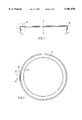
- FIG. 1 is a cross-sectional view of the cover or lid of FIG. 1, applied to the top of a container;
- FIG. 2 is a bottom view of the cover or lid of FIG. 1, showing the safety band or ring with its tear-off lip portion.
- FIG. 3 is a partial cross-sectional view in enlarged scale of the cover or lid in accordance with the invention, in stacked position on a second cover or lid of the invention;
- FIG. 3a is a partial cross-sectional view of the lower end of the cover or lid showing the safety band or ring.
- FIG. 4 is an enlarged view of the detail A in FIG. 1;
- FIG. 5 is a fragmentary bottom view at an enlarged scale of the detail B of the tear-off lip portion of FIG. 2 of the safety band or ring;
- FIG. 6 is a fragmentary perspective view of the cover or lid with the tear-off lip portion partially pivoted away from the safety band or ring to illustrate the construction of the safety band or ring in the area of the tear-off lip.
- FIG. 1 there is shown a pilferproof or tamper resistant cover 10 or lid of the invention mounted on top of a container, such as a metallic container (only the upper end portion thereof being shown).
- the cover 10 has a circular end wall 12.
- a cylindrical skirt 14 extends downwardly from the outer periphery of the end wall 12.
- An annular rib 16 extends upwardly from the upper surface 18 of the end wall 12.
- the annular rib 16 has a truncated cross-sectional shape and it is spaced radially inwardly from the outer cylindrical surface 14a of the cylindrical skirt 14 or from the outer peripheral edge of the end wall 12.
- the cylindrical skirt 14 has on its radially inner cylindrical surface 14b a radially inwardly projecting annular nose 20 disposed approximately centrally between the upper axial end and the lower axial end 15 of the cylindrical skirt 14.
- the nose 20 has a lower surface 22 and an upper surface 24 as well as rounded surface 26 interconnecting the lower surface 22 and the upper surface 24.
- the lower surface 22 is inclined downwardly toward the lower end 15 of the annular skirt 14 at an acute angle a' of approximately 5 degrees with respect to a radial line normal to the longitudinal axial centerline x--x (FIG. 1) of the cover.
- the upper surface 24 is inclined at a larger angle a" of approximately 45° with respect to a radial line normal to the longitudinal axis x--x of the cover.
- the upper surface is connected by a radiused surface portion 24a to the axial inner wall 14b of the cylindrical skirt 14.
- An annular safety ring or guarantee strip 30 is connected at its upper end 30a by means of a thin tear-off connection 32 to the lower end 15 of the cylindrical skirt 14.
- the safety ring 30, as shown in FIG. 3 is generally teardrop-shaped or half teardrop-shaped in cross-section and generally inclined radially inwardly from its upper end 30a at the tear-off connection 32 to its lower end 30b.
- the lower end 30b of the safety ring 30 has a diameter larger than the outer diameter of the rib 16 but smaller than the outer diameter of the skirt 14 or the outer diameter of end wall 12.
- the safety ring 30 has a generally flat outer surface 34 extending from the upper end 30a to the lower end 30b of the safety ring 30.
- the flat outer surface 34 is tapered inwardly at an acute angle ⁇ of approximately 19° with respect to the outer surface of the skirt 14 or an axial line extending parallel to the longitudinal centerline x--x of the cover 10.
- the safety ring 30 has furthermore a convex, inwardly bulged inner surface 36 consisting of a generally flat inner upper surface section 36a and a curved inner lower surface section 36b.
- the maximum thickness T of the safety ring 30 is closer to its lower end 30b than to its upper end 30a.
- the flat upper surface section 36a extends from the upper end 30a of the safety ring 30 to approximate a mid point of the axial length of the safety ring 30.
- the lower surface section 36b extends from the lower end of the flat upper surface section 36a and forms the lower end 30b of the safety ring 30.
- the curved inner lower surface section 36b of the safety ring 30 has a first intermediate curved surface portion 36b' having a first radius of curvature R1, a second curved surface portion 36b" between the intermediate curved surface portion 36b' and the flat inner upper surface section 36a and having a second radius of curvature R2, and a third curved surface portion 36b'" between the intermediate curved surface portion 36b' and the flat outer surface 34 at the lower end 30b of the safety ring 30 and having a third radius of curvature R3, wherein the second radius of curvature R2 is smaller than the first radius of curvature R1 and the third radius of curvature R3 is smaller than the second radius of curvature R2.
- the flat upper surface section 36a is inclined inwardly from the upper end 30a of the safety ring 30 at an angle ⁇ of approximately 48°. This facilitates conventional rolling on of the cover onto a container without the need for special tools for widening or enlarging the cover at the end of the safety ring.
- a plurality of covers can be safety stacked on one another for packaging and shipment.
- the lower end 30b of the generally inwardly inclined safety ring 30 of each cover will engage the surface portion of the upper wall 18 of the end wall 12 of an adjacent underlying cover radially outwardly of the annular rib 16 between the rib 16 and the outer periphery of the end wall 12.
- the annular rib 16 resists undesired relative movement of the covers in the stack in a direction transverse to the longitudinal centerline of the covers to the extent that the covers cannot slip-off from one another in transverse direction whereby the covers can be safely stacked on one another to provide a stable stack facilitating packaging and shipment.
- an adjacent underlying cover is schematically indicated in phantom lines.
- the cover has a tab 40 which is connected by narrow rupturable connections 42a, 42b, 42c as shown in the enlarged detail of FIG. 4, the perspective view of FIG. 5 and also in FIG. 6, to the safety ring 30 and the skirt 14.
- the tab 40 is adapted to be grasped by the user's fingers for tearing off the safety ring 30 from the lower end of the cylindrical or circumferential skirt 14 along the connection 32.
- the tab 40 is generally parallel to the skirt 14 and is accordingly disposed at an angle with respect to the radially inwardly inclined safety ring 30. This facilitates grasping of the tab for tearing off the safety ring 30 from the skirt 14 of the cover 10.
- the tab 40 does extend radially beyond the skirt 14 in order to prevent interference of the covers 10 with one another or with the cover manipulating machines during fabrication and stacking of the covers 10 and also during application of the covers 10 to the containers.
- FIG. 1 a pilferproof or tamper resistant cover 10 is shown engaged on a container C, such as a metallic container.
- a container C such as a metallic container.
- the container C has at its upper end a circumferential flange 50 projecting from the outer circumferential wall 52 of the container C.
- the cover 10 is placed on the container C the flange 50 is received within the circumferential skirt 14 between the end wall 12 of the cover 10 and the radially inwardly projecting nose 26.
- the lower portion of the circumferential flange 50 has a decreasing diameter and is contoured to correspond substantially to the inwardly inclined shape of the upper surface 24 of the nose 20.
- the container C Spaced below the circumferential flange 50 the container C has in its outer wall 52 a circumferential radially outwardly opening groove 54 which is adapted to partly receive the safety ring 30 therein.
- the groove 54 has a rounded bottom portion 56 and two diverging side portions 58 interconnecting the rounded bottom portion 56 with the outer surface of the outer circumferential wall 52 of the container.
- the inclination of the diverging upper side wall portion 58 of the groove 54 corresponds generally to the inclination of the flat upper inner surface section 36a of the safety ring 30.
- the lower portion of the safety ring 30 extends into the groove 54 and the lowermost end of the safety ring 30 is at least closely adjacent or contacts the lower inclined side surface 58 of the groove 54.
- the diameter of the safety ring 30 at the lower end 30b thereof, namely the diameter of the safety ring 30 at the lower end of the flat outer surface 34 is generally identical to the diameter of the outer surface of the outer circumferential wall 52 of the container C. Accordingly, the lower end portion of the safety ring 30 is tightly nested within the groove 54 thereby providing a generally smooth transition between the lower end of the inwardly inclined safety ring 30 and the outer surface of the container outer wall 52 making it impossible to remove the cover 10 from the container without previously tearing off the safety ring 30.
- the radially inwardly projecting nose 20 at the inner wall of the skirt 14 may also be formed closely adjacent to the lower end 15 of the circumferential skirt 14.
- the cover is preferably formed of plastic material.
- the safety band 30 is weakened and does not extend upwardly the full height of the safety band up to the lower end 15 of the circumferential skirt 14.
- Radially inwardly of the tab 40 the safety band 30 has a cut-out portion 60 extending over a circumferential length generally corresponding to the circumferential length of the tear-off tab 40.
- the cut-out portion 60 is bounded at its lower end by a remaining web portion 62 of the safety ring 30 and is bounded at its upper end by the lower end 15 of the skirt 14.
- the tear-off tab 40 has on its outer surface the narrow rupturable connections 42a to connect the tab 40 to the skirt 14 and has on its inner surface narrow rupturable connections 42b connecting the tab 40 to the remaining web portion 62 of the safety ring 30.
- a radial triangular wall portion 64 connects the tab 40 at its rear end to the safety ring 30.
- FIG. 5 the tear-off tab 40 is shown in an outwardly opened position with the narrow connections 42a between the tear-off tab 40 and the skirt 14 as well as the narrow connections 42b between lower remaining web portion 62 of the safety ring 30 ruptured prior to fully tearing off the safety ring 30 from the remaining portion of the cover 10.
- the remaining web portion 62 is connected by a rupturable tab 42c to the safety ring 30 as also shown in FIG. 5.
Abstract
Description
Claims (13)
Priority Applications (6)
| Application Number | Priority Date | Filing Date | Title |
|---|---|---|---|
| US08/891,054 US5901870A (en) | 1997-07-10 | 1997-07-10 | Pilferproof cover and a container associated therewith |
| CA002218776A CA2218776A1 (en) | 1997-07-10 | 1997-10-21 | A pilferproof cover and a container associated therewith |
| JP9307841A JPH1135054A (en) | 1997-07-10 | 1997-10-22 | Cover for preventing contents pilferage |
| AU43583/97A AU748889B2 (en) | 1997-07-10 | 1997-10-28 | A pilferproof cover and a container associated therewith |
| KR1019970058056A KR19990013239A (en) | 1997-07-10 | 1997-11-04 | Cut-out cover and associated container |
| MYPI97005320A MY132663A (en) | 1997-07-10 | 1997-11-10 | A pilferproof cover and a container associated therewith |
Applications Claiming Priority (1)
| Application Number | Priority Date | Filing Date | Title |
|---|---|---|---|
| US08/891,054 US5901870A (en) | 1997-07-10 | 1997-07-10 | Pilferproof cover and a container associated therewith |
Publications (1)
| Publication Number | Publication Date |
|---|---|
| US5901870A true US5901870A (en) | 1999-05-11 |
Family
ID=25397541
Family Applications (1)
| Application Number | Title | Priority Date | Filing Date |
|---|---|---|---|
| US08/891,054 Expired - Fee Related US5901870A (en) | 1997-07-10 | 1997-07-10 | Pilferproof cover and a container associated therewith |
Country Status (6)
| Country | Link |
|---|---|
| US (1) | US5901870A (en) |
| JP (1) | JPH1135054A (en) |
| KR (1) | KR19990013239A (en) |
| AU (1) | AU748889B2 (en) |
| CA (1) | CA2218776A1 (en) |
| MY (1) | MY132663A (en) |
Cited By (5)
| Publication number | Priority date | Publication date | Assignee | Title |
|---|---|---|---|---|
| KR19990013239A (en) * | 1997-07-10 | 1999-02-25 | 라인스 홀딩스 쏘시에떼 아노님. | Cut-out cover and associated container |
| US20100181323A1 (en) * | 2009-01-20 | 2010-07-22 | Anchor Packaging, Inc. | Food container having improved tamper evident features |
| USD739234S1 (en) | 2012-12-19 | 2015-09-22 | Sonoco Development, Inc. | Container overcap |
| US9340332B2 (en) | 2013-03-15 | 2016-05-17 | Sonoco Development, Inc. | Closure for container |
| US20210179323A1 (en) * | 2019-12-11 | 2021-06-17 | Berry Global, Inc. | Tamper Evident Closure |
Families Citing this family (2)
| Publication number | Priority date | Publication date | Assignee | Title |
|---|---|---|---|---|
| US7134567B2 (en) | 2001-04-12 | 2006-11-14 | Ropak Corporation | Pull tab on tear strip on plastic cover plastic cover, including break tab feature, and related apparatus and methods |
| JP2008207829A (en) * | 2007-02-26 | 2008-09-11 | Morinaga Milk Ind Co Ltd | Over-cap with pilfer-proof band |
Citations (16)
| Publication number | Priority date | Publication date | Assignee | Title |
|---|---|---|---|---|
| GB955276A (en) * | 1960-03-29 | 1964-04-15 | Emnosa Soc De Personnes A Resp | Improvements in and relating to tamper-proof containers |
| CA954475A (en) * | 1971-07-19 | 1974-09-10 | George W. Faulstich | Neck for wide-mouth jar and cap therefor |
| US3979003A (en) * | 1973-08-10 | 1976-09-07 | Buckeye Molding Co. | Re-usable frangible closure |
| US4066181A (en) * | 1976-03-16 | 1978-01-03 | Buckeye Molding Company | Container and closure assembly |
| GB1509548A (en) * | 1976-10-14 | 1978-05-04 | Glyndon Plastics Ltd | Tamper-proof closure caps for containers |
| FR2412469A1 (en) * | 1977-12-21 | 1979-07-20 | Astra Plastique | Screw cap for container - has cylindrical skirt tear-off security strip and locking ribs engaging in neck grooves |
| US4438857A (en) * | 1982-07-12 | 1984-03-27 | Three Sisters Ranch Enterprises | Cap and neck structure for a wide-mouth jar |
| US4625876A (en) * | 1982-07-12 | 1986-12-02 | Cap Snap Co., Inc. | Cap and neck structure for a wide mouth jar |
| DE3623765A1 (en) * | 1985-07-18 | 1987-01-22 | Friedrich Stettler | Tamper-indicating closure cap, and container fitted with this cap |
| US4678094A (en) * | 1986-04-29 | 1987-07-07 | Bankers Trust Co. | Tamper-resistant container cap |
| US4691834A (en) * | 1982-07-12 | 1987-09-08 | Bankers Trust Company | Cap and neck structure for a wide mouth jar |
| US4790448A (en) * | 1987-09-08 | 1988-12-13 | Liberty Diversified Industries | Container and lid with tamper evident closure |
| US4903849A (en) * | 1989-04-24 | 1990-02-27 | Irwin Wallman | Tamper evident cap and bottle |
| US5092478A (en) * | 1991-05-20 | 1992-03-03 | Pierre Maurice | Tamper-evident tear-off strip for container cap |
| US5115934A (en) * | 1990-11-28 | 1992-05-26 | Highland Plastics, Inc. | Tamper resistant container lid |
| US5224616A (en) * | 1992-08-17 | 1993-07-06 | Northern Engineering And Plastics Corp. | Non-replaceable snap on cap for school milk bottles |
Family Cites Families (3)
| Publication number | Priority date | Publication date | Assignee | Title |
|---|---|---|---|---|
| US4988880A (en) * | 1989-02-03 | 1991-01-29 | Eastman Kodak Company | X-ray intensifying screen containing hafnia phosphor |
| JPH09110058A (en) * | 1995-10-16 | 1997-04-28 | Meita Kasei Kk | Tight sealing lid |
| US5901870A (en) * | 1997-07-10 | 1999-05-11 | Lynes Holdings S.A. | Pilferproof cover and a container associated therewith |
-
1997
- 1997-07-10 US US08/891,054 patent/US5901870A/en not_active Expired - Fee Related
- 1997-10-21 CA CA002218776A patent/CA2218776A1/en not_active Abandoned
- 1997-10-22 JP JP9307841A patent/JPH1135054A/en active Pending
- 1997-10-28 AU AU43583/97A patent/AU748889B2/en not_active Ceased
- 1997-11-04 KR KR1019970058056A patent/KR19990013239A/en not_active Application Discontinuation
- 1997-11-10 MY MYPI97005320A patent/MY132663A/en unknown
Patent Citations (16)
| Publication number | Priority date | Publication date | Assignee | Title |
|---|---|---|---|---|
| GB955276A (en) * | 1960-03-29 | 1964-04-15 | Emnosa Soc De Personnes A Resp | Improvements in and relating to tamper-proof containers |
| CA954475A (en) * | 1971-07-19 | 1974-09-10 | George W. Faulstich | Neck for wide-mouth jar and cap therefor |
| US3979003A (en) * | 1973-08-10 | 1976-09-07 | Buckeye Molding Co. | Re-usable frangible closure |
| US4066181A (en) * | 1976-03-16 | 1978-01-03 | Buckeye Molding Company | Container and closure assembly |
| GB1509548A (en) * | 1976-10-14 | 1978-05-04 | Glyndon Plastics Ltd | Tamper-proof closure caps for containers |
| FR2412469A1 (en) * | 1977-12-21 | 1979-07-20 | Astra Plastique | Screw cap for container - has cylindrical skirt tear-off security strip and locking ribs engaging in neck grooves |
| US4691834A (en) * | 1982-07-12 | 1987-09-08 | Bankers Trust Company | Cap and neck structure for a wide mouth jar |
| US4438857A (en) * | 1982-07-12 | 1984-03-27 | Three Sisters Ranch Enterprises | Cap and neck structure for a wide-mouth jar |
| US4625876A (en) * | 1982-07-12 | 1986-12-02 | Cap Snap Co., Inc. | Cap and neck structure for a wide mouth jar |
| DE3623765A1 (en) * | 1985-07-18 | 1987-01-22 | Friedrich Stettler | Tamper-indicating closure cap, and container fitted with this cap |
| US4678094A (en) * | 1986-04-29 | 1987-07-07 | Bankers Trust Co. | Tamper-resistant container cap |
| US4790448A (en) * | 1987-09-08 | 1988-12-13 | Liberty Diversified Industries | Container and lid with tamper evident closure |
| US4903849A (en) * | 1989-04-24 | 1990-02-27 | Irwin Wallman | Tamper evident cap and bottle |
| US5115934A (en) * | 1990-11-28 | 1992-05-26 | Highland Plastics, Inc. | Tamper resistant container lid |
| US5092478A (en) * | 1991-05-20 | 1992-03-03 | Pierre Maurice | Tamper-evident tear-off strip for container cap |
| US5224616A (en) * | 1992-08-17 | 1993-07-06 | Northern Engineering And Plastics Corp. | Non-replaceable snap on cap for school milk bottles |
Cited By (7)
| Publication number | Priority date | Publication date | Assignee | Title |
|---|---|---|---|---|
| KR19990013239A (en) * | 1997-07-10 | 1999-02-25 | 라인스 홀딩스 쏘시에떼 아노님. | Cut-out cover and associated container |
| US20100181323A1 (en) * | 2009-01-20 | 2010-07-22 | Anchor Packaging, Inc. | Food container having improved tamper evident features |
| USD739234S1 (en) | 2012-12-19 | 2015-09-22 | Sonoco Development, Inc. | Container overcap |
| USD739233S1 (en) | 2012-12-19 | 2015-09-22 | Sonoco Development, Inc. | Container overcap |
| US9340332B2 (en) | 2013-03-15 | 2016-05-17 | Sonoco Development, Inc. | Closure for container |
| US20210179323A1 (en) * | 2019-12-11 | 2021-06-17 | Berry Global, Inc. | Tamper Evident Closure |
| US11939115B2 (en) * | 2019-12-11 | 2024-03-26 | Berry Global, Inc. | Tamper evident closure |
Also Published As
| Publication number | Publication date |
|---|---|
| MY132663A (en) | 2007-10-31 |
| CA2218776A1 (en) | 1999-01-10 |
| AU748889B2 (en) | 2002-06-13 |
| JPH1135054A (en) | 1999-02-09 |
| KR19990013239A (en) | 1999-02-25 |
| AU4358397A (en) | 1999-01-21 |
Similar Documents
| Publication | Publication Date | Title |
|---|---|---|
| US4966292A (en) | Cap and neck finish for a wide mouth container | |
| US5775527A (en) | Closure cap with anti-tamper strip | |
| US8100303B2 (en) | Closure for a container | |
| US5305931A (en) | Multi-functional, environmentally-oriented, tamper-evident container closure | |
| EP0056906B1 (en) | Container closure arrangement | |
| US4470513A (en) | Tamper-indicating closure | |
| US5050754A (en) | Cap for a neck finish on a wide mouth container | |
| US20140166659A1 (en) | Package formed by container and overcap | |
| US4154360A (en) | Overcap and container assembly | |
| US4423822A (en) | Closure cap with thumb actuated removal assisting tab | |
| EP0939734B1 (en) | Closure cap for closure of a container mouth | |
| EP2987745B1 (en) | A cap seal | |
| US4032029A (en) | Tamper-proof bottle cap and container | |
| EP0334514A1 (en) | Lid retaining collar | |
| JPH0329756A (en) | Cap to seal neck of bottle | |
| JPH0219255A (en) | Wrench-opening and identifiable vessel cap having seal disk holding means | |
| JPS5940704B2 (en) | container lid | |
| US4146148A (en) | Frangible closure for containers and method | |
| US5901870A (en) | Pilferproof cover and a container associated therewith | |
| EP0979780B1 (en) | A pilferproof cover and a container associated therewith | |
| US5065888A (en) | Improved ringless paint container with step down lid | |
| JP4392873B2 (en) | Plastic container lid | |
| US3392871A (en) | Container with opening means | |
| US5103995A (en) | Ringless paint container with step down lid | |
| JP3196916B2 (en) | Plastic overcap |
Legal Events
| Date | Code | Title | Description |
|---|---|---|---|
| AS | Assignment |
Owner name: LYNES HOLDINGS S.A., LUXEMBOURG Free format text: ASSIGNMENT OF ASSIGNORS INTEREST;ASSIGNOR:WAGNER, ARMAND;REEL/FRAME:008662/0457 Effective date: 19970701 |
|
| FEPP | Fee payment procedure |
Free format text: PAYOR NUMBER ASSIGNED (ORIGINAL EVENT CODE: ASPN); ENTITY STATUS OF PATENT OWNER: SMALL ENTITY |
|
| AS | Assignment |
Owner name: L&M SERVICES B.V., NETHERLANDS Free format text: ASSIGNMENT OF ASSIGNORS INTEREST;ASSIGNOR:LYNES HOLDING S.A.;REEL/FRAME:010909/0539 Effective date: 20000425 |
|
| FEPP | Fee payment procedure |
Free format text: PAT HOLDER NO LONGER CLAIMS SMALL ENTITY STATUS, ENTITY STATUS SET TO UNDISCOUNTED (ORIGINAL EVENT CODE: STOL); ENTITY STATUS OF PATENT OWNER: SMALL ENTITY |
|
| REFU | Refund |
Free format text: REFUND - SURCHARGE, PETITION TO ACCEPT PYMT AFTER EXP, UNINTENTIONAL (ORIGINAL EVENT CODE: R2551); ENTITY STATUS OF PATENT OWNER: SMALL ENTITY |
|
| FPAY | Fee payment |
Year of fee payment: 4 |
|
| FEPP | Fee payment procedure |
Free format text: PAT HOLDER CLAIMS SMALL ENTITY STATUS, ENTITY STATUS SET TO SMALL (ORIGINAL EVENT CODE: LTOS); ENTITY STATUS OF PATENT OWNER: SMALL ENTITY |
|
| FPAY | Fee payment |
Year of fee payment: 8 |
|
| FEPP | Fee payment procedure |
Free format text: ENTITY STATUS SET TO SMALL (ORIGINAL EVENT CODE: SMAL); ENTITY STATUS OF PATENT OWNER: SMALL ENTITY |
|
| REMI | Maintenance fee reminder mailed | ||
| LAPS | Lapse for failure to pay maintenance fees | ||
| STCH | Information on status: patent discontinuation |
Free format text: PATENT EXPIRED DUE TO NONPAYMENT OF MAINTENANCE FEES UNDER 37 CFR 1.362 |
|
| FP | Lapsed due to failure to pay maintenance fee |
Effective date: 20110511 |