US589675A - yoelmy - Google Patents
yoelmy Download PDFInfo
- Publication number
- US589675A US589675A US589675DA US589675A US 589675 A US589675 A US 589675A US 589675D A US589675D A US 589675DA US 589675 A US589675 A US 589675A
- Authority
- US
- United States
- Prior art keywords
- shaft
- rack
- clutch
- bar
- motion
- Prior art date
- Legal status (The legal status is an assumption and is not a legal conclusion. Google has not performed a legal analysis and makes no representation as to the accuracy of the status listed.)
- Expired - Lifetime
Links
Images

Classifications
-
- F—MECHANICAL ENGINEERING; LIGHTING; HEATING; WEAPONS; BLASTING
- F03—MACHINES OR ENGINES FOR LIQUIDS; WIND, SPRING, OR WEIGHT MOTORS; PRODUCING MECHANICAL POWER OR A REACTIVE PROPULSIVE THRUST, NOT OTHERWISE PROVIDED FOR
- F03B—MACHINES OR ENGINES FOR LIQUIDS
- F03B13/00—Adaptations of machines or engines for special use; Combinations of machines or engines with driving or driven apparatus; Power stations or aggregates
- F03B13/12—Adaptations of machines or engines for special use; Combinations of machines or engines with driving or driven apparatus; Power stations or aggregates characterised by using wave or tide energy
- F03B13/14—Adaptations of machines or engines for special use; Combinations of machines or engines with driving or driven apparatus; Power stations or aggregates characterised by using wave or tide energy using wave energy
- F03B13/16—Adaptations of machines or engines for special use; Combinations of machines or engines with driving or driven apparatus; Power stations or aggregates characterised by using wave or tide energy using wave energy using the relative movement between a wave-operated member, i.e. a "wom" and another member, i.e. a reaction member or "rem"
- F03B13/18—Adaptations of machines or engines for special use; Combinations of machines or engines with driving or driven apparatus; Power stations or aggregates characterised by using wave or tide energy using wave energy using the relative movement between a wave-operated member, i.e. a "wom" and another member, i.e. a reaction member or "rem" where the other member, i.e. rem is fixed, at least at one point, with respect to the sea bed or shore
- F03B13/1805—Adaptations of machines or engines for special use; Combinations of machines or engines with driving or driven apparatus; Power stations or aggregates characterised by using wave or tide energy using wave energy using the relative movement between a wave-operated member, i.e. a "wom" and another member, i.e. a reaction member or "rem" where the other member, i.e. rem is fixed, at least at one point, with respect to the sea bed or shore and the wom is hinged to the rem
- F03B13/181—Adaptations of machines or engines for special use; Combinations of machines or engines with driving or driven apparatus; Power stations or aggregates characterised by using wave or tide energy using wave energy using the relative movement between a wave-operated member, i.e. a "wom" and another member, i.e. a reaction member or "rem" where the other member, i.e. rem is fixed, at least at one point, with respect to the sea bed or shore and the wom is hinged to the rem for limited rotation
- F03B13/1815—Adaptations of machines or engines for special use; Combinations of machines or engines with driving or driven apparatus; Power stations or aggregates characterised by using wave or tide energy using wave energy using the relative movement between a wave-operated member, i.e. a "wom" and another member, i.e. a reaction member or "rem" where the other member, i.e. rem is fixed, at least at one point, with respect to the sea bed or shore and the wom is hinged to the rem for limited rotation with an up-and-down movement
-
- Y—GENERAL TAGGING OF NEW TECHNOLOGICAL DEVELOPMENTS; GENERAL TAGGING OF CROSS-SECTIONAL TECHNOLOGIES SPANNING OVER SEVERAL SECTIONS OF THE IPC; TECHNICAL SUBJECTS COVERED BY FORMER USPC CROSS-REFERENCE ART COLLECTIONS [XRACs] AND DIGESTS
- Y02—TECHNOLOGIES OR APPLICATIONS FOR MITIGATION OR ADAPTATION AGAINST CLIMATE CHANGE
- Y02E—REDUCTION OF GREENHOUSE GAS [GHG] EMISSIONS, RELATED TO ENERGY GENERATION, TRANSMISSION OR DISTRIBUTION
- Y02E10/00—Energy generation through renewable energy sources
- Y02E10/30—Energy from the sea, e.g. using wave energy or salinity gradient
Definitions
- This invention has reference to certain imT provements in that class of motors which are designed for utilizing the power of the waves to produce a continuous rotary motion for the purpose of supplying power for various purposes; and the invention consists of a wave-motor in which a float-actuated lever is raised and lowered by the rising and falling waves and is guided in its up and down motion by suitable piles, said lever being pivotally connected with a rack-bar which is guided in a suitable box that is independently pivoted on a transmittingshaft, so as to fol low the oscillating motion of the rack-bar in its up-anddown motion.
- a loose pinion which meshes with the rack-bar and which is connected with a clutch, the members of which may be thrown in and out of mesh, so that the rotary motion of the pinion and transmittingshaft is transmitted to the driving-shaft, from which the power produced by the rising and falling of the float is again transmitted by suitable mechanism, as will be fully described hereinafter and finally pointed out in the claim.
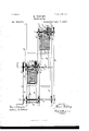
- Figure 1 represents a side elevation of my improved wave-motor
- Fig. 2 is a plan view of the same, partly in horizontal section.
- A represents a supporting-frame which is supported on piles a, that are driven into the ground at the bot tom of the sea along the coast and at a suitable distance from the same.
- the frame A consists, mainly, of a number of longitudinal supporting-beams, which are transversely braced together so as to form a structure of sufiicient strength capable of resisting the )owerof the waves.
- transverse shaft 1) or 1) on which swing levers B to the outer ends of which is applied a float 13, which is constructed of layers of wood or of hollow sheet metal or other suitable material.
- the float B is firmly attached to the lovers B and is provided at opposite sides with antifrictionrollers b, the, axes of which are supported in suitable bearin gs attached to the float B.
- the rollers I) serve for guiding the float while it is raised or lowered in following the up-and-down motion or swell of the waves, so that the float is prevented against being jarred or impeded by lateral moved up or down by the rising or falling of the float-actuated lever B.
- the box D is made of two parts, which are bolted together and provided with special guideways for the rack-bar O.
- the rack-bar C meshes with the pinion G, that is placed loosely on the shaft S, and the hub of which is provided with one member of a clutch C the teeth of which mesh with the second and sliding member of the clutch that is also placed on the shaft S and is actuated by a helical spring C that is interposed between it and the adjacent end of the box I), as shown in Fig. 2.
- the second member of the clutch C is splinedin the usual manner onto the transmitting-shaft S, so that it can be moved in the direction of the axis of the shaft 5 but prevented from axial rotation on the same.
- a fulcrumed lever 13 which can be moved in one direction against the tension of the spring C when it is desired to place the members of the clutch C out of mesh with each other, or which can be moved in the opposite direction when it is desired to bring the two members of the clutch into mesh with each other, in which position they are held by the spring acting on the slidin g member.
- two or morewave-motors which are built in the same manner as the one described and arranged at a distance corresponding to the average length of the waves from each other, so that they are alternately operated upon by the waves, and thereby continuous motion transmitted to the driving-shaft S, by which the power is transmitted by suitable pumping mechanism or machinery, according to the purpose for which the motor is constructed.
- a wave-motor the combination of a supporting-frame, an actuating-lever, a stationary pivot on which the lever is fulcrumed, a float fixed to the outer end of the lever, a rack-bar pivoted to the outer end of the lever, a transmitting-shaft journaled in the frame, a guide-box pivoted on the transmitting-shaft and provided with ways for said rack-bar, a gear-wheel on said transmitting-shaft with which the rack-bar is held in mesh by the guide-box, and a clutch on said shaft formed of a member attached to said gear-wheel, and a spring-actuated member splined to said shaft, substantially as set forth.
Landscapes
- Engineering & Computer Science (AREA)
- Chemical & Material Sciences (AREA)
- Combustion & Propulsion (AREA)
- Mechanical Engineering (AREA)
- General Engineering & Computer Science (AREA)
- Other Liquid Machine Or Engine Such As Wave Power Use (AREA)
Description
2 Sh eets-Sheet 1.
(No Model.) H. VOELMY.
WAVE MOTOR. No. 589,675. Patented Sept. 7, 1897.
' WITNESSES: J Q INVENTOR WW '4 WT A noimzys.
(N0 Mudeh) 2 Sheets-Sheet 2 H. VOELMY.
WAVE MOTOR.
No. 589,675. Patented Sept. '7, 1897.
ATTORNEYS.
1M5 uonms mn'cns cu, PHOKO'LIYNQ. WASHINGTON. a c.
HENRI VOELMY,.OF NEW YORK, N. Y.
WAVE-MOTCR.
SE EGIFZGATION forming part of Letters Patent No. 589,675, dated September '7, 1897'.
' Application filed June 2. 1897. {Serial No, 639,128. No model.)
Be it known that I, HENRI VonLMY, a citizen of the United States, residing in the city, county, and State of New York, have invented certain new and useful Improvements in Nave-Motors, of which the following is a specification.
This invention has reference to certain imT provements in that class of motors which are designed for utilizing the power of the waves to produce a continuous rotary motion for the purpose of supplying power for various purposes; and the invention consists of a wave-motor in which a float-actuated lever is raised and lowered by the rising and falling waves and is guided in its up and down motion by suitable piles, said lever being pivotally connected with a rack-bar which is guided in a suitable box that is independently pivoted on a transmittingshaft, so as to fol low the oscillating motion of the rack-bar in its up-anddown motion. On the transmitting-shaft is mounted a loose pinion, which meshes with the rack-bar and which is connected with a clutch, the members of which may be thrown in and out of mesh, so that the rotary motion of the pinion and transmittingshaft is transmitted to the driving-shaft, from which the power produced by the rising and falling of the float is again transmitted by suitable mechanism, as will be fully described hereinafter and finally pointed out in the claim.
In the accompanying drawings, Figure 1 represents a side elevation of my improved wave-motor, and Fig. 2 is a plan view of the same, partly in horizontal section.
Similar letters of reference indicate corresponding parts.
Referring to the drawings, A represents a supporting-frame which is supported on piles a, that are driven into the ground at the bot tom of the sea along the coast and at a suitable distance from the same. The frame A consists, mainly, of a number of longitudinal supporting-beams, which are transversely braced together so as to form a structure of sufiicient strength capable of resisting the )owerof the waves. To transversel *o ositesupporting-piles of the beams A is applied a transverse shaft 1) or 1) on which swing levers B, to the outer ends of which is applied a float 13, which is constructed of layers of wood or of hollow sheet metal or other suitable material. The float B is firmly attached to the lovers B and is provided at opposite sides with antifrictionrollers b, the, axes of which are supported in suitable bearin gs attached to the float B. The rollers I) serve for guiding the float while it is raised or lowered in following the up-and-down motion or swell of the waves, so that the float is prevented against being jarred or impeded by lateral moved up or down by the rising or falling of the float-actuated lever B.
The box D is made of two parts, which are bolted together and provided with special guideways for the rack-bar O. The rack-bar C meshes with the pinion G, that is placed loosely on the shaft S, and the hub of which is provided with one member of a clutch C the teeth of which mesh with the second and sliding member of the clutch that is also placed on the shaft S and is actuated by a helical spring C that is interposed between it and the adjacent end of the box I), as shown in Fig. 2. The second member of the clutch C is splinedin the usual manner onto the transmitting-shaft S, so that it can be moved in the direction of the axis of the shaft 5 but prevented from axial rotation on the same. To the hub of the splined member of the clutch O is applied the innerforlred end of a fulcrumed lever 13, which can be moved in one direction against the tension of the spring C when it is desired to place the members of the clutch C out of mesh with each other, or which can be moved in the opposite direction when it is desired to bring the two members of the clutch into mesh with each other, in which position they are held by the spring acting on the slidin g member. When the members of the clutch C are placed in mesh with each other, the rotation imparted to the pinion C by the reciprocating motion of the rack-bar is transmitted to the shaft S during the upward mo tion of the rack-bar, while during the downward motion of the rack-bar the clutch member on the hub of the pinion passes loosely over the teeth of the splined and spring-actuated member of the clutch without transmitting power to the shaft S. It appears thus that by every upward movement of the lever B intermittent rotary motion is transmitted to the shaft S. This motion is preferably transmitted by a belt-and-pulley transmission T to a second driving-shaft S, which is supported in independent hearings on the supporting-beams A.
In order to impart continuous motion to the driving-shaft, it is preferable to provide two or morewave-motors, which are built in the same manner as the one described and arranged at a distance corresponding to the average length of the waves from each other, so that they are alternately operated upon by the waves, and thereby continuous motion transmitted to the driving-shaft S, by which the power is transmitted by suitable pumping mechanism or machinery, according to the purpose for which the motor is constructed. By coupling in this manner a number of wave-motors together and transmitting the intermittent motion of the same to the driving-shaft a comparatively cheap source of power is obtained that may be used along the sea-coast for irrigating and other purposes.
I do not broadly claim a wave-motor'comprising a supporting-frame, a series of pivoted actuating-levers provided with floats V fixed to their outer ends, rack-bars pivoted 40 to the outer ends of said levers, and suitable gearing in connection with the racks for transmitting power.
Having thus described my invention, what I claim is In a wave-motor, the combination of a supporting-frame, an actuating-lever, a stationary pivot on which the lever is fulcrumed, a float fixed to the outer end of the lever, a rack-bar pivoted to the outer end of the lever, a transmitting-shaft journaled in the frame, a guide-box pivoted on the transmitting-shaft and provided with ways for said rack-bar, a gear-wheel on said transmitting-shaft with which the rack-bar is held in mesh by the guide-box, and a clutch on said shaft formed of a member attached to said gear-wheel, and a spring-actuated member splined to said shaft, substantially as set forth.
In testimony that I claim the foregoing as my invention 1 have signed my name in presence of two subscribing witnesses.
HENRI VOELMY.
\Vitnesses:
PAUL GoEPEL, GEO. W. J AEKEL.
Publications (1)
| Publication Number | Publication Date |
|---|---|
| US589675A true US589675A (en) | 1897-09-07 |
Family
ID=2658337
Family Applications (1)
| Application Number | Title | Priority Date | Filing Date |
|---|---|---|---|
| US589675D Expired - Lifetime US589675A (en) | yoelmy |
Country Status (1)
| Country | Link |
|---|---|
| US (1) | US589675A (en) |
-
0
- US US589675D patent/US589675A/en not_active Expired - Lifetime
Similar Documents
| Publication | Publication Date | Title |
|---|---|---|
| US1061061A (en) | Wave-motor. | |
| US979320A (en) | Current-motor. | |
| US851549A (en) | Wave-motor. | |
| US854082A (en) | Wave-power motor. | |
| US1187708A (en) | Mechanical doll-actuating mechanism. | |
| US1004025A (en) | Baling-press. | |
| US913561A (en) | Wave-motor. | |
| US1009592A (en) | Wave-motor. | |
| US558615A (en) | saladee | |
| US676467A (en) | Water-motor. | |
| US955542A (en) | Cotton-folder. | |
| US1143599A (en) | Mining-machine. | |
| US366958A (en) | Motor | |
| US582000A (en) | Submerged current-motor | |
| US1068353A (en) | Swing. | |
| US1204088A (en) | Wave-motor. | |
| US592581A (en) | blagq | |
| US583821A (en) | sager | |
| US1098517A (en) | Wave-motor. | |
| US388586A (en) | Horse-power | |
| US421761A (en) | Tidal motor | |
| US703871A (en) | Current-wheel. | |
| US412974A (en) | Post or pile driving machine | |
| US1190131A (en) | Gearing. | |
| US1092777A (en) | Trench-digging machine. |