US589552A - mcwade - Google Patents
mcwade Download PDFInfo
- Publication number
- US589552A US589552A US589552DA US589552A US 589552 A US589552 A US 589552A US 589552D A US589552D A US 589552DA US 589552 A US589552 A US 589552A
- Authority
- US
- United States
- Prior art keywords
- spindle
- chart
- disk
- apertures
- cradle
- Prior art date
- Legal status (The legal status is an assumption and is not a legal conclusion. Google has not performed a legal analysis and makes no representation as to the accuracy of the status listed.)
- Expired - Lifetime
Links
- 230000033001 locomotion Effects 0.000 description 23
- 210000003128 head Anatomy 0.000 description 12
- PEDCQBHIVMGVHV-UHFFFAOYSA-N Glycerine Chemical compound OCC(O)CO PEDCQBHIVMGVHV-UHFFFAOYSA-N 0.000 description 11
- 235000019892 Stellar Nutrition 0.000 description 10
- 238000010276 construction Methods 0.000 description 4
- 239000000463 material Substances 0.000 description 3
- 230000009466 transformation Effects 0.000 description 3
- 230000000694 effects Effects 0.000 description 2
- 241001121515 Celes Species 0.000 description 1
- 101001044101 Rattus norvegicus Lipopolysaccharide-induced tumor necrosis factor-alpha factor homolog Proteins 0.000 description 1
- 240000008042 Zea mays Species 0.000 description 1
- 235000005824 Zea mays ssp. parviglumis Nutrition 0.000 description 1
- 235000002017 Zea mays subsp mays Nutrition 0.000 description 1
- 239000003086 colorant Substances 0.000 description 1
- 235000005822 corn Nutrition 0.000 description 1
- 235000015250 liver sausages Nutrition 0.000 description 1
- 210000001747 pupil Anatomy 0.000 description 1
- 238000009877 rendering Methods 0.000 description 1
- 239000007779 soft material Substances 0.000 description 1
Images



Classifications
-
- G—PHYSICS
- G09—EDUCATION; CRYPTOGRAPHY; DISPLAY; ADVERTISING; SEALS
- G09B—EDUCATIONAL OR DEMONSTRATION APPLIANCES; APPLIANCES FOR TEACHING, OR COMMUNICATING WITH, THE BLIND, DEAF OR MUTE; MODELS; PLANETARIA; GLOBES; MAPS; DIAGRAMS
- G09B27/00—Planetaria; Globes
- G09B27/04—Star maps
Definitions
- This invention relates to devices for illustrating the relative positions and movements of the heavenly bodies; and the object is to provide asimple device of a mechanical charactor for, illustrating the relative movements of the sun, earth, and moon about their axes, and the orbital movements as well, in connection with a stellar chart showing the stars of both the northern and southern hemispheres or the principal stars thereof.
- This chart is so arranged that by a mechanical shift the stars of either hemisphere may be made to appear significantly, at will, to correspond with the position. of the earth in its orbit.
- This shift or transformation may be effected by rendering one set of stars transparent while the others are opaque, or the sets of stars maybe made distinguishable by contrasting colors, or by one set being made to appear black and the other white, and these distinctions may be effected by transmitting light through star-apertures in the chart or by reflected light, all as will be hereinafter more particularly explained.
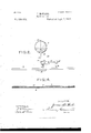
- Figure 1 is a plan view of the apparatus on a comparatively small scale, about one-sixth of the preferred natural size.
- Fig. 2 is a side elevation thereof.
- Fig. 8 is adissected View of the base of the apparatus bearing the stellar chart, illustrating the construction for producing the star transformation or shift.
- Fig. 4: is a transverse section of the base on line as in Figs. 1 and 3. The remaining figures areLdrawn to a larger scale and illustrate the mechanism for producing the movements of the sun, earth, and moon.
- Fig.6 is a side elevation of the mechanism.
- Fig. 6 is a plan
- Fig. 7 is a plan showing the mechanism below the line :0 in Fig. 5.
- Fig. 8 is a transverse section in the plane of the axis of the spindle 4.
- the base A comprises a square frame in which is a circular stellar chart a, on which are marked the principal stars of both hemispheres, here indicated merely by a few circular apertures s, supposed to represent the stars of the northern hemisphere, and other apertures .9 supposed to represent those of the southern hemisphere.
- a circular stellar chart a on which are marked the principal stars of both hemispheres, here indicated merely by a few circular apertures s, supposed to represent the stars of the northern hemisphere, and other apertures .9 supposed to represent those of the southern hemisphere.
- the construction illustrated in Figs. 3 andd is employed. Under the chart a, broken away in Fig.
- the disk I) may be rocked or shifted loy-any convenient means.
- the disk has at one side a lug b, which has a limited play in a recess formed in the distancing piece or sheet of pasteboard of the base A.
- Operating-tabs b and b are connected by cords or tapes with the respective sides of the disk.
- the tab 11 By drawing on the tab 11 for example, the disk is rocked or rotated in one direction, and by drawing on the tab Z1 it is rotated in the opposite direction.
- the movement in each direction is' so limited by the lugs b that at each terminus of the same one set of stellar apertures in the chart a will be put in register with the corresponding set of apertures in the disk I).
- Figsl and 3 In order to designate which set of stars is displayed on the chart, the device illustrated in Figsl and 3 maybe employed.
- a hinged strip On a hinged strip are inscribed the words ,Southern celestial hemisphere and Northern celes tial hemisphere, and the free end of this strip is coupled to the tab 12 so that when this tab is drawn upon the inscription Southern celestial hemisphere will appear at a sight opening a in the frame about the chart a. ⁇ Vhen the tab Z2 is pulled or drawn upon, the other inscription will appear at the sightopening.
- This cradle is adapted to slide endwise to and fro in bearings on the head, and to guide the eradle in its movement a longitudinal central rod 6 on the cradle plays through apertured lugs 5 on the head.
- the cradle has also two racks 6" at its base, which play in guides 5 on the head 5.
- a toothed wheel 7 On the spindle 4 in the frame 3 is fixed a toothed wheel 7, which gears with a toothed wheel 8, fixed on the driving-arbor 9, this latter being squared, as here shown, to receive a key.
- the wheel 7 is connected, through a train of gears 10, with a toothed wheel 11, fixed on a tubular or hollow spindle 12, embracing the spindle 4 and extending up to the head 5 thereon.
- the effect of the train 10 is to cause the spindles 4 and 12 to rotate in opposite directions when the arbor 9 is rotated.
- a toothed wheel 13 On the upper end of the hollow spindle 12 is fixed, directly beneath the head 5, a toothed wheel 13, and with it gears a Wheel 14, fixed on an upright arbor 15 in the head.
- This arbor 15 carries on its upper end a toothed Wheel 16, which gears with a pinion 17 on the same upright arbor with a crown-wheel 18, which latter gears with a pinion 19 on the same horizontal arbor with a toothed wheel 20.
- the wheel 20 gears with a longpinion 2].
- the arbor or spindle 22, on which the earth E is fixed, is secured in one end of the long pinion 21 and rotates therewith.
- the effect ofrotating the operating-arbor 9 is to rotate the head 5 and cradle 6 about the spindle 4 as an axis and to rotate the hollow spindle l2 and wheel 13 in the opposite direction.
- the wheel 13 drives the wheel 14. and through it andthe wheels 16,17,18,10,and 20 it drives the long pinion 21, thus imparting the proper axial rotation to the earth E.
- the moon M is carried by a tubular spindle 23 on the spindle 22, and is driven from the latter at the proper speed through the medium of toothed wheels 24 and 25 on the respective spindles 22 and 23 and suitable connecting-gears 26 on the end of the cradle "3.
- the orbital motion is imparted to the moon.
- the sun S is mounted on an upright spindle 27, mounted in abearing on the end of the cradle 6 opposite to that where the earth is mounted, and it has the proper axial rotation imparted to it by a wheel 28 on the spindle 27, which gears with and is driven by a toothed wheel 29 on the end ofthe long pinion 21.
- a mutilated-gear wheel 30 Fixed indirectly to the tubular spindle 12, in the plane of the two racks 6 on the cradle 6 and between the latter, is a mutilated-gear wheel 30, having teeth 011 but one-half of its periphery. These teeth gear alternately with the racks (5 and consequently continuous rotation of the wheel 30 in one direction imparts a reciprocating to-and-fro motion to the cradle 6 in its guides. This motion, combined with the rotary motion of the cradle about the spindle 4 as a center, produces the proper elliptical movement of the earth in its orbit.
- the wheel 30 is secured by a set-screw to the sleeve-like boss of the wheel 13, which latter is fixed to the spindle 2; but this is only a feature of construction and does not relate to the invention.
- the sun S may be fixed on its upright spindle, if desired. However, I prefer to mount it frictionally thereon, sothat it can be moved or adjusted up or down on the spindle 27, as desired, in order to illustrate better the varying angles of the earths axis with the plane passing through the earth and sun. As shown in Fig. 2, friction-nuts 31, of some soft material, are placed on the spindle 27 above and below the sun S, to hold it in place; but any suitable frictional device may be employed as well.
- Figs. 1 and 2 the cradle 6 is represented as covered by an iuclosing cap 2 to hide the mechanism and prevent it from distracting the attention. of the pupil. This, however, is not essential, nor is it necessary to inclose the mechanism in the frame 3, as indicated in Fig. 2.
- the bar or plate 1 is only a convenient means of connecting the gearing of the planetarium to the base A, and it may be of any form or construction and of any material.
- a base for a planetarium comprising a stationary stellar chart having stars of both hemispheres marked on it by apertures, a rotating disk behind said chart and adapted for partial rotation, means for limiting such rotation, and means for effecting such rotation, said disk having also the stars of the different hemispheres marked thereon and adapted to be brought into register with the star-apertures in the chart, substantially as set forth.
Landscapes
- Physics & Mathematics (AREA)
- General Physics & Mathematics (AREA)
- Engineering & Computer Science (AREA)
- Astronomy & Astrophysics (AREA)
- Business, Economics & Management (AREA)
- Educational Administration (AREA)
- Educational Technology (AREA)
- Theoretical Computer Science (AREA)
- Instructional Devices (AREA)
Description
(No Model.) 4 SheetsSh eet 1.
J. MOWADB.
PLANETARIUM. No. 589,552. Patented Sept. 7,1897.
UNIVERSAL PLANISPHERE I SOUTHER CELEBTIAL HEMISPHEREJJ FIGZI. v 6% INVENTORI fX/W/W Quiz/Mam WITNESSES: I
wzw mg Ahtorney.
(No Model.) 4 Sheets sheet 2. J. MGWADE.
PLANETARIUM.
No. 539,552. Patented Sept. 7,1897.
F'l G14.
INVENTOR:
WIE E2ES1 V X. W M
4 E D A PLANETARIUM.
Pate nted Sept. 7,1897.
s 0 UTHERN GELESTIAL HEM'ISPHEREa INVENTOR: am fi do By Jan Attorney,
WITNESSES:
(N0 Modl.) V 4 Sheets-Sheet 4. J. MOWADE.
PLANETARIUM. No. 589,552. Patented Sept. 7,1897.
WITNESSES W 9M W 3,, Q/WVH @044 Attorney.
UNITED STATES PATE T @rrrcn.
JAMES hlClVADE, OF NElV YORK, N. Y.
PLAN ETARIUM.
.SPECIFICATION forming part of Letters Iatent No. 589,552, dated September *7, 1897.
' Application filed January 7,1897. Serial No. 618,279. (No model.)
To all Ill/"1 0122, 1'1? m l/ 1 con/corn,
Be it known [-h at I, JAMES McWADE, a citi zen of the United States, residing in the city, county, and State of New York, have invented certain new and useful Improvements in Planetariums, of which the following is a specification.
This invention. relates to devices for illustrating the relative positions and movements of the heavenly bodies; and the object is to provide asimple device of a mechanical charactor for, illustrating the relative movements of the sun, earth, and moon about their axes, and the orbital movements as well, in connection with a stellar chart showing the stars of both the northern and southern hemispheres or the principal stars thereof. This chart is so arranged that by a mechanical shift the stars of either hemisphere may be made to appear significantly, at will, to correspond with the position. of the earth in its orbit. This shift or transformation may be effected by rendering one set of stars transparent while the others are opaque, or the sets of stars maybe made distinguishable by contrasting colors, or by one set being made to appear black and the other white, and these distinctions may be effected by transmitting light through star-apertures in the chart or by reflected light, all as will be hereinafter more particularly explained.
The invention will'be more minutely described with reference to the accompanying drawings, which illustrate an embodiment of the same. i
Figure 1 is a plan view of the apparatus on a comparatively small scale, about one-sixth of the preferred natural size. Fig. 2 is a side elevation thereof. Fig. 8 is adissected View of the base of the apparatus bearing the stellar chart, illustrating the construction for producing the star transformation or shift. Fig. 4: is a transverse section of the base on line as in Figs. 1 and 3. The remaining figures areLdrawn to a larger scale and illustrate the mechanism for producing the movements of the sun, earth, and moon. Fig.6 is a side elevation of the mechanism. Fig. 6 is a plan, and Fig. 7 is a plan showing the mechanism below the line :0 in Fig. 5. Fig. 8 is a transverse section in the plane of the axis of the spindle 4.
any desired tint or color.
I will first describe the base A, which bears the stellar chart or map, promising that this chart is adapted to show, by shifting or transformation on a circular field, the stars or the principal stars ofboth the northern and southern hemispheres.
Referring to Figs. 1, 3, and 4, the base A comprises a square frame in which is a circular stellar chart a, on which are marked the principal stars of both hemispheres, here indicated merely by a few circular apertures s, supposed to represent the stars of the northern hemisphere, and other apertures .9 supposed to represent those of the southern hemisphere. In order that the stars of one hemisphere only may be indicated at one time, say by transmitted light, the construction illustrated in Figs. 3 andd is employed. Under the chart a, broken away in Fig. 3, is rotatively mounted a circular disk I), havingin it two sets of apertures c and 0 so placed that by rocking the disk about its center 0 the set of apertures 0 may be brought into register with the apertures s in the chart a. or the apertures c into register with the apertures s in the chart. \Vhen either set of stellar apertures .5" or s is brought thus into register with those of the disk I), the light will pass through thereat and produce bright points of light, simulating stars, while those of the other set remain opaque.
The disk I) may be rocked or shifted loy-any convenient means. As shown in Fig. 3, the disk has at one side a lug b, which has a limited play in a recess formed in the distancing piece or sheet of pasteboard of the base A. Operating-tabs b and b are connected by cords or tapes with the respective sides of the disk. By drawing on the tab 11 for example, the disk is rocked or rotated in one direction, and by drawing on the tab Z1 it is rotated in the opposite direction. The movement in each direction is' so limited by the lugs b that at each terminus of the same one set of stellar apertures in the chart a will be put in register with the corresponding set of apertures in the disk I). v
If it be desired to transmit colored light at the stellar apertures, it is only necessary to cover the face of 'the disk b with a piece of thin translucent material, as tissue-paper, of If light is to be transmitted as bright points to represent the stars, very small holes, as pin -holes, will suffice.
In order to designate which set of stars is displayed on the chart, the device illustrated in Figsl and 3 maybe employed. On a hinged strip are inscribed the words ,Southern celestial hemisphere and Northern celes tial hemisphere, and the free end of this strip is coupled to the tab 12 so that when this tab is drawn upon the inscription Southern celestial hemisphere will appear at a sight opening a in the frame about the chart a. \Vhen the tab Z2 is pulled or drawn upon, the other inscription will appear at the sightopening.
Around the margins of the chart a are marked the graduations representing the degrees of the circle, the twelve monthly divisions, and the names of the four seasons. These are clearly shown in Fig. 1, although I have notdeemed it necessary therein to extend the graduations entirely around the circle.
I will now describe the mechanism for illustrating the movements of the sun, earth, and moon, as illustrated in Figs. 1, 2, 5, 6, 7, and S. This mechanism is designated as a whole in Figs. 1 and 2 by B. S represents the sun, E the earth, and M the moon. At the back of the base A is fixed a bar or plate 1, that has on it atubular bearing 2, which extends up through the center of the chart a. The disk 1) turns about this bearing-piece. Mounted on the plate 1 at its back is a frame 3, in which is mounted a spindle 4, which extends upward through the bearing 2 and rotates therein. On the upper end of this is fixed a head 5, on which is mounted a cradle 6. This cradle is adapted to slide endwise to and fro in bearings on the head, and to guide the eradle in its movement a longitudinal central rod 6 on the cradle plays through apertured lugs 5 on the head. The cradle has also two racks 6" at its base, which play in guides 5 on the head 5.
On the spindle 4 in the frame 3 is fixed a toothed wheel 7, which gears with a toothed wheel 8, fixed on the driving-arbor 9, this latter being squared, as here shown, to receive a key. The wheel 7 is connected, through a train of gears 10, with a toothed wheel 11, fixed on a tubular or hollow spindle 12, embracing the spindle 4 and extending up to the head 5 thereon. The effect of the train 10 is to cause the spindles 4 and 12 to rotate in opposite directions when the arbor 9 is rotated.-
On the upper end of the hollow spindle 12 is fixed, directly beneath the head 5, a toothed wheel 13, and with it gears a Wheel 14, fixed on an upright arbor 15 in the head. This arbor 15 carries on its upper end a toothed Wheel 16, which gears with a pinion 17 on the same upright arbor with a crown-wheel 18, which latter gears with a pinion 19 on the same horizontal arbor with a toothed wheel 20. The wheel 20 gears with a longpinion 2].,
which has bearings at its ends in the ends of the cradle 6. The arbor or spindle 22, on which the earth E is fixed, is secured in one end of the long pinion 21 and rotates therewith.
The effect ofrotating the operating-arbor 9 is to rotate the head 5 and cradle 6 about the spindle 4 as an axis and to rotate the hollow spindle l2 and wheel 13 in the opposite direction. The wheel 13 drives the wheel 14. and through it andthe wheels 16,17,18,10,and 20 it drives the long pinion 21, thus imparting the proper axial rotation to the earth E.
The moon M is carried by a tubular spindle 23 on the spindle 22, and is driven from the latter at the proper speed through the medium of toothed wheels 24 and 25 on the respective spindles 22 and 23 and suitable connecting-gears 26 on the end of the cradle "3. Thus the orbital motion is imparted to the moon.
The sun S is mounted on an upright spindle 27, mounted in abearing on the end of the cradle 6 opposite to that where the earth is mounted, and it has the proper axial rotation imparted to it by a wheel 28 on the spindle 27, which gears with and is driven by a toothed wheel 29 on the end ofthe long pinion 21.
The above-described mechanism imparts the proper axial rotation to the sun and earth. the proper orbital movement to the moon about the earth,and a circular orbital move ment to the earth and moon about the sun. It now remains to explain the means employed for imparting the elliptical orbital motion to the earth.
Fixed indirectly to the tubular spindle 12, in the plane of the two racks 6 on the cradle 6 and between the latter, is a mutilated-gear wheel 30, having teeth 011 but one-half of its periphery. These teeth gear alternately with the racks (5 and consequently continuous rotation of the wheel 30 in one direction imparts a reciprocating to-and-fro motion to the cradle 6 in its guides. This motion, combined with the rotary motion of the cradle about the spindle 4 as a center, produces the proper elliptical movement of the earth in its orbit.
As shown in Fig. 8, the wheel 30 is secured by a set-screw to the sleeve-like boss of the wheel 13, which latter is fixed to the spindle 2; but this is only a feature of construction and does not relate to the invention.
The sun S may be fixed on its upright spindle, if desired. However, I prefer to mount it frictionally thereon, sothat it can be moved or adjusted up or down on the spindle 27, as desired, in order to illustrate better the varying angles of the earths axis with the plane passing through the earth and sun. As shown in Fig. 2, friction-nuts 31, of some soft material, are placed on the spindle 27 above and below the sun S, to hold it in place; but any suitable frictional device may be employed as well.
In Figs. 1 and 2 the cradle 6 is represented as covered by an iuclosing cap 2 to hide the mechanism and prevent it from distracting the attention. of the pupil. This, however, is not essential, nor is it necessary to inclose the mechanism in the frame 3, as indicated in Fig. 2.
The bar or plate 1 is only a convenient means of connecting the gearing of the planetarium to the base A, and it may be of any form or construction and of any material.
I have called the spheres'S, E, and M the sun, earth, and moon, respectively, for convenience of description. They merely simulate these bodies,of course,as in an y planetarium. They may be of any suitable material and may have geographical markings, if desired but this is not essential to my invention.
Having thus described my invention, I claim 1. A base for a planetarium comprising a stationary stellar chart having stars of both hemispheres marked on it by apertures, a rotating disk behind said chart and adapted for partial rotation, means for limiting such rotation, and means for effecting such rotation, said disk having also the stars of the different hemispheres marked thereon and adapted to be brought into register with the star-apertures in the chart, substantially as set forth.
2. In the base A of the planetarium, the combination with the fixed stellar chart a, having in it two .sets of apertures s and s representing respectively the stars of the two hemispheres, of the rotatable disk I), back of said chart, said disk having in it two sets of apertures c and adapted to be brought, respectively, into register with the sets of apertures s and by the rotatory movement of the disk, means for limiting the extent of rotation of said disk, and means for rotating said disk, substantially as set forth.
3. In the base A of the planetarium, the combination with the fixed stellar chart (4, having in it two sets of apertures s and 8 representing respectively the stars of the two hemispheres, of the rotatable disk I), back of said chart, said disks having in it two sets of apertures c and 0 adapted to be brought, respectively, into register with the sets of apertures s and s by the rotatory movement of the disk, means for limiting the extent of rotation. of said disk, tabs b and b con nected to opposite sides of said disk for operating the same, and a hinged strip 0 bearing inscriptions, arranged behind a sightopening in the face of the base A, and con-' nected with one of the said tabs, whereby said hinged strip is operated when the disk I) is shifted, substantially as set forth.
4. In a planetarium, the combination with an upright spindle 4, carrying a head 5, the said head, and a cradle mounted for reciprocating movement on said head transversely to the axis of the spindle 4:, of the tubular spindle 12, a train of gears connecting the spindles a and 12', whereby they are rotated simultaneously in opposite directions, the long pinion 21, in the cradle, a gearing-train between the spindle 12 and said pinion, whereby the pinion is rotated therefrom as the head turns, racks (if on the cradle, a mutilated-gear wheel on the shaft 12 adapted to engage said racks alternately and thus impart a reciprocating movement to the cradle, a sphere E, carried by the pinion 21, and representing the earth, the tubular spindle 23, on the spindle carrying the earth, gearing between the pinion 21 and spindle 23 whereby the former drives the latter, a sphere M, carried by the spindle 23 and representing the moon, an upright spindle 27, on the cradle, gearing between the pinion 21 and said spindle, whereby the former drives the latter, and a sphere S on said spindle 27, representing the sun, substantially as set forth.
5. In a planetarium, the combination with the cradle 6, and mechanism for imparting thereto a rotary movement and a reciprocating movement at right angles to the plane of said rotary movement, of the spheres representing the earth and moon carried by said cradle, mechanism for imparting the proper rotatory and orbital movements to said spheres, the upright spindle 27, mechanism for rotating the same, and the sphere S, representing the sun, mounted adj ustably in said spindle 27, so that it may be shifted up or down thereon at will, substantially as set forth.
In witness whereof I have hereunto signed my name in the presence of two subscribing witnesses.
JAMES MCIVA'TDE.
IVitnesses:
HENRY CONNETT, PETER A. Boss.
Publications (1)
| Publication Number | Publication Date |
|---|---|
| US589552A true US589552A (en) | 1897-09-07 |
Family
ID=2658215
Family Applications (1)
| Application Number | Title | Priority Date | Filing Date |
|---|---|---|---|
| US589552D Expired - Lifetime US589552A (en) | mcwade |
Country Status (1)
| Country | Link |
|---|---|
| US (1) | US589552A (en) |
-
0
- US US589552D patent/US589552A/en not_active Expired - Lifetime
Similar Documents
| Publication | Publication Date | Title |
|---|---|---|
| US1701582A (en) | Road or course indicator for motor vehicles, vessels, aircraft, or the like | |
| US3305946A (en) | Apparatus simulating the illumination of earth by the sun at any time and date | |
| KR100996849B1 (en) | Astro Motion Simulator | |
| US3520073A (en) | Multifunction astronomical display planetarium | |
| US3387393A (en) | Toy planetarium | |
| US521725A (en) | Worth | |
| US1750505A (en) | Astronomical clock | |
| US501136A (en) | geeaoey | |
| US2098296A (en) | Planetarium | |
| US247289A (en) | Astral lantern | |
| US1484174A (en) | Device for indicating the relative movements of the earth, sun, and moon | |
| US1157219A (en) | Terrestrial globe. | |
| US554809A (en) | Astronomical chart | |
| US1289849A (en) | Method of teaching and illustrating. | |
| US469719A (en) | Tellurian | |
| US459871A (en) | E morris peters co | |
| CN2186945Y (en) | Toy planetarium | |
| US1478099A (en) | Terrestrial planetarium | |
| US279439A (en) | Planescope | |
| US402005A (en) | deichmann | |
| US3255539A (en) | Planetarium | |
| US1135204A (en) | Tellurian. | |
| SU1464199A1 (en) | Astronomy and geography teaching appliance | |
| SU144054A1 (en) | Astronomy Tutorial | |
| GB425108A (en) | Improvements in or relating to apparatus for teaching cosmography |