US5894533A - Device for wavelength-related stabilization of an optical filter - Google Patents
Device for wavelength-related stabilization of an optical filter Download PDFInfo
- Publication number
- US5894533A US5894533A US08/812,239 US81223997A US5894533A US 5894533 A US5894533 A US 5894533A US 81223997 A US81223997 A US 81223997A US 5894533 A US5894533 A US 5894533A
- Authority
- US
- United States
- Prior art keywords
- grating
- bragg grating
- optical
- filter
- wavelength
- Prior art date
- Legal status (The legal status is an assumption and is not a legal conclusion. Google has not performed a legal analysis and makes no representation as to the accuracy of the status listed.)
- Expired - Lifetime
Links
Images

Classifications
-
- G—PHYSICS
- G02—OPTICS
- G02B—OPTICAL ELEMENTS, SYSTEMS OR APPARATUS
- G02B6/00—Light guides; Structural details of arrangements comprising light guides and other optical elements, e.g. couplings
- G02B6/10—Light guides; Structural details of arrangements comprising light guides and other optical elements, e.g. couplings of the optical waveguide type
- G02B6/12—Light guides; Structural details of arrangements comprising light guides and other optical elements, e.g. couplings of the optical waveguide type of the integrated circuit kind
- G02B6/12007—Light guides; Structural details of arrangements comprising light guides and other optical elements, e.g. couplings of the optical waveguide type of the integrated circuit kind forming wavelength selective elements, e.g. multiplexer, demultiplexer
- G02B6/12009—Light guides; Structural details of arrangements comprising light guides and other optical elements, e.g. couplings of the optical waveguide type of the integrated circuit kind forming wavelength selective elements, e.g. multiplexer, demultiplexer comprising arrayed waveguide grating [AWG] devices, i.e. with a phased array of waveguides
- G02B6/12019—Light guides; Structural details of arrangements comprising light guides and other optical elements, e.g. couplings of the optical waveguide type of the integrated circuit kind forming wavelength selective elements, e.g. multiplexer, demultiplexer comprising arrayed waveguide grating [AWG] devices, i.e. with a phased array of waveguides characterised by the optical interconnection to or from the AWG devices, e.g. integration or coupling with lasers or photodiodes
-
- G—PHYSICS
- G02—OPTICS
- G02B—OPTICAL ELEMENTS, SYSTEMS OR APPARATUS
- G02B6/00—Light guides; Structural details of arrangements comprising light guides and other optical elements, e.g. couplings
- G02B6/10—Light guides; Structural details of arrangements comprising light guides and other optical elements, e.g. couplings of the optical waveguide type
- G02B6/12—Light guides; Structural details of arrangements comprising light guides and other optical elements, e.g. couplings of the optical waveguide type of the integrated circuit kind
- G02B6/12007—Light guides; Structural details of arrangements comprising light guides and other optical elements, e.g. couplings of the optical waveguide type of the integrated circuit kind forming wavelength selective elements, e.g. multiplexer, demultiplexer
- G02B6/12009—Light guides; Structural details of arrangements comprising light guides and other optical elements, e.g. couplings of the optical waveguide type of the integrated circuit kind forming wavelength selective elements, e.g. multiplexer, demultiplexer comprising arrayed waveguide grating [AWG] devices, i.e. with a phased array of waveguides
- G02B6/12026—Light guides; Structural details of arrangements comprising light guides and other optical elements, e.g. couplings of the optical waveguide type of the integrated circuit kind forming wavelength selective elements, e.g. multiplexer, demultiplexer comprising arrayed waveguide grating [AWG] devices, i.e. with a phased array of waveguides characterised by means for reducing the temperature dependence
- G02B6/12028—Light guides; Structural details of arrangements comprising light guides and other optical elements, e.g. couplings of the optical waveguide type of the integrated circuit kind forming wavelength selective elements, e.g. multiplexer, demultiplexer comprising arrayed waveguide grating [AWG] devices, i.e. with a phased array of waveguides characterised by means for reducing the temperature dependence based on a combination of materials having a different refractive index temperature dependence, i.e. the materials are used for transmitting light
Definitions
- the present invention is directed to a device for the wavelength-related stabilization of an optical filter, particularly a wavelength-division multiplexer/demultiplexer.
- Wavelength-division multiplex/demultiplex methods wherein different information are transmitted simultaneously by the same fiber on frequency channels defined by different optical carrier frequencies, are being increasingly utilized for the transmission and distribution of information via optical fibers, for example glass fibers.
- Narrow-band optical filters are required for the multiplexing and demultiplexing of these optical channels.
- a temperature-stabilization of the filters and/or the employment of a reference wavelength have already been proposed for solving this problem.
- the reference wavelength can be utilized as either being centrally distributed or locally distributed.
- the central distribution is rather unfavorable, since the optical channel thereby employed is not available for useful signal transmission or is only available therefor to a limited extent.
- the present invention is based on the object of offering a new possibility for the local stabilization of the optical filter with the assistance of a reference wavelength.
- This object is achieved in an improvement for a device for wavelength-related stabilization of an optical filter, particularly a wavelength-division multiplexer/demultiplexer, with the improvements comprising a Bragg grating being arranged in the proximity of the filter and means for supplying a predetermined, fixed optical reference wavelength to the Bragg grating.
- the Bragg grating employed in the invention offers great freedom with respect to the filter band width and a high edge steepness, see, for example, U.S. Pat. No. 4,815,081, which claims priority from the same German Reference as EP 0 284 908 B1, and which U.S. Patent is incorporated herein by reference thereto.
- the reference wavelength that is employed can be utilized locally and/or centrally distributed.
- the means for providing the reference wavelength is an optical waveguide, such as a strip waveguide, which is integratedly formed on the substrate with the Bragg grating, either independent of the filter or with the filter.
- the means for supplying the optical reference wavelength can also be an optical fiber, which may be attached to the substrate with the Bragg grating.
- the invention is also directed to a method for wavelength-stabilizing an optical filter having a device with a Bragg grating arranged in the proximity of the filter and means for supplying an optical reference wavelength to the Bragg grating, said method including regulating the Bragg grating to a maximum transmission and/or minimum reflection of the reference wavelength by controlling the grating constant of the grating or by controlling the grating constant of the grating to regulate the minimum transmission and maximum reflection of the reference wavelength.
- the optical filter is executed as integrated-optical filter in glass material, for example as a phased array in SiO 2 on silicon substrates (see R. Adar et al. "Broad-Band Array Multiplexers Made with Silica Waveguides on Silicon", IEEE J. Lightwave Technology, Vol. 11, 1993, pp. 212-221), the one advantageous embodiment is comprised therein that an additional, strip-like waveguide for guiding the reference wavelength in which the Bragg grating can be inscribed in a further process step is integrated on the substrate next to the filter.
- an additional, strip-like waveguide for guiding the reference wavelength in which the Bragg grating can be inscribed in a further process step is integrated on the substrate next to the filter.
- a further waveguide for supplying and/or carrying the reference waveguides to or, respectively, away from the substrate must be coupled to the integrated waveguide for guiding the reference wavelength, and, given operation of this grating in transmission, two additional waveguides must be coupled to the substrate, one for supplying the reference wavelength to the substrate and the other for carrying the reference wavelength away from the substrate.
- a Bragg grating which is inscribed in an optical fiber preferably composed of glass, is employed. This enables a significantly simpler structure, since the grating must merely be secured in a stable fashion with good contact in the proximity of the filter. This device can be subsequently applied to existing filters without having to alter the outlay of, for example, an integrated optical filter.
- optical filters for example phased arrays
- Bragg gratings are also possible in a semiconductor material, for example InGaAsP/InP (see M. Zirngibl et al, "Demonstration of a 15 ⁇ 15 Arrayed Wavelength Demultiplexer in InP", IEEE Photon. Technology Letters, Vol. 4, 1992, pp. 1250-1253) or spectrometers (see C. Cremer et al. "Grating Spectrograph in InGaAsP/InP for Dense Wavelength Division Multiplexing", Applied Physics Letters, Vol. 59, 1991, pp. 627-629).
- FIG. 1 is a schematic plan view of a first exemplary embodiment of the present invention
- FIG. 2 is a schematic plan view of a second exemplary embodiment of the present invention.
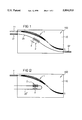
- FIG. 3 is a transmission curve of a Bragg grating.
- FIGS. 1 and 2 which has an optical filter 1 in the form of a wavelength-division multiplexer/demultiplexer for multiplexing and/or demultiplexing a plurality N ⁇ 1 wavelength channels is respectively formed on a surface 100 of the substrate.
- the multiplexer/demultiplexer 1 of FIGS. 1 and 2 is fashioned, for example, in the form of a phased array, such as mentioned and disclosed in the above-mentioned U.S. Application, and this U.S. Application is incorporated by reference for a description of forming the multiplexer-demultiplexer.
- a phased array 1 When the phased array 1 is operated as a demultiplexer, a plurality of wavelength channels are supplied to the phased array 1, for example an optical fiber 11, and are spatially separated from one another in the phased array 1, after which the separated channels can be taken from individual outfeed waveguides.
- the phased array 1 is operated as a multiplexer, the outfeed waveguide functions in an infeed waveguide for the individual channels that are merged in the phased array 1 and forwarded in common in the fiber 11.
- the invention is not limited to the specific structure of the optical filter, but can be applied in all optical filters.
- the Bragg grating 2 is arranged in the proximity of the filter 1, a predetermined optical reference wavelength ⁇ 0 is supplied to this Bragg grating 2, whereby a wavelength transmission characteristic of the Bragg grating 2 in reflection and/or transmission with reference to the reference wavelength ⁇ 0 is exploited independently of the wavelength channels transmitted via the filter.
- FIGS. 1 and 2 are configured so that the Bragg grating 2 is arranged with an optical waveguide, which is provided for guiding the reference wavelength ⁇ 0 that is preferably a strip-like waveguide 20 in FIG. 1 and an optical fiber 20' in FIG. 2.
- a strip-like waveguide is a waveguide that comprises a longitudinal axis along which the optical wave guided in the waveguide propagates and whereby the guided wave is laterally limited at both sides of the longitudinal axis.
- Examples of such strip-like waveguides are integrated striplines, such as, for example, rib waveguides or diffused-in striplines, but also optical fibers.
- the phased array 1, shown by way of example, is essentially composed of integrated strip-like waveguides.
- the Bragg grating 2 and the strip-like waveguide 20, which are provided for guiding the reference wavelength ⁇ 0, are integrated on the surface 100 of the substrate 10.
- the reference wavelength ⁇ 0 can, for example, be supplied in an optical fiber 21 and be coupled into the integrated waveguide 20. A part of the reference waveguide ⁇ 0 reflected by the Bragg grating 2 can be supplied to an optical detector through this fiber 21. A part of the reference wavelength ⁇ 0 transmitted through the Bragg grating 2 can likewise be supplied to an optical detector through an optical fiber 22 coupled to the integrated waveguide.
- the fiber 21 suffices by itself when only the part of the reference wavelength ⁇ 0 reflected by the grating 2 is used.
- the part transmitted through the grating 2 is used by itself or in addition to the reflected part, the fiber 22 must be additionally present.
- the fiber 22 could also be employed as a fiber for coupling the reference wavelength ⁇ 0 into the integrated waveguide 20.
- an integrated strip-like waveguide of the phased array 1 itself could also be employed as an integrated waveguide 20, in which the Bragg grating 2 would then be formed. In this case, however, one channel of the optical filter 1 would be lost. It is, therefore, more expedient when the waveguide 20 provided for guiding the reference wavelength ⁇ 0 and the Bragg grating 2 are integrated on the substrate 10 separately from the filter 1, as shown in FIG. 1.
- the Bragg grating 2 is formed in a waveguide 20' in the form of an optical fiber provided for guiding the reference wavelength ⁇ 0 that is applied to the substrate 10 on which the optical filter 1 is integrated.
- the fiber 20' is glued onto the surface 100 of the substrate 10.
- the fiber 20' for example, is bent horseshoe-shaped so that indeed and outfeed are at the same side of the substrate 10 given employment of the part of the reference wavelength ⁇ 0 transmitted through the Bragg grating 2.
- the Bragg grating 2 is expediently fashioned in a straight leg of the horseshoe-shaped fiber 20'.
- the fiber 20' of FIG. 2 could also exhibit a course similar to the integrated waveguide 20 of FIG. 1.
- the integrated waveguide 20 of FIG. 1 could also have a horseshoe-shaped course similar to the fiber 20' of FIG. 2.
- the Bragg grating 2 schematically shown in FIGS. 1 and 2 usually qualitatively comprises a transmission curve, as shown in FIG. 3, for example, given fixed grating constant.
- FIG. 3 shows the attenuation, measured in dB, of the light transmitted through the Bragg grating 2 dependent on the wavelength ⁇ .
- the illustrated typical transmission curve K exhibits a sharp minimum at the specific wavelength ⁇ 0 that is employed as a reference wavelength. This will correspond to the maximum transmission and a minimum reflection of the grating 2.
- the inventive device is advantageously operated so that the Bragg grating 2 is regulated to a minimum reflection and a maximum transmission of the constant reference wavelength ⁇ 0 by controlling the grating constant a of the grating 2.
- the control of the grating constant a can occur, for example, via the temperature T of the grating 2, at which the optical filter 1 located in the proximity is also at.
- the grating 2 is regulated to a minimum transmission and/or maximum reflection of the constant reference wavelength ⁇ 0 by controlling the grating constant a of the grating 2.
- the grating constant can be regulated by temperature of the grating 2.
Landscapes
- Physics & Mathematics (AREA)
- Engineering & Computer Science (AREA)
- Microelectronics & Electronic Packaging (AREA)
- General Physics & Mathematics (AREA)
- Optics & Photonics (AREA)
- Optical Integrated Circuits (AREA)
- Diffracting Gratings Or Hologram Optical Elements (AREA)
- Semiconductor Lasers (AREA)
- Optical Communication System (AREA)
- Lasers (AREA)
Abstract
Description
Claims (10)
Applications Claiming Priority (2)
| Application Number | Priority Date | Filing Date | Title |
|---|---|---|---|
| DE19608732 | 1996-03-06 | ||
| DE19608732 | 1996-03-06 |
Publications (1)
| Publication Number | Publication Date |
|---|---|
| US5894533A true US5894533A (en) | 1999-04-13 |
Family
ID=7787440
Family Applications (1)
| Application Number | Title | Priority Date | Filing Date |
|---|---|---|---|
| US08/812,239 Expired - Lifetime US5894533A (en) | 1996-03-06 | 1997-03-06 | Device for wavelength-related stabilization of an optical filter |
Country Status (6)
| Country | Link |
|---|---|
| US (1) | US5894533A (en) |
| EP (1) | EP0794445B1 (en) |
| JP (1) | JPH09243856A (en) |
| KR (1) | KR970066615A (en) |
| DE (1) | DE59712047D1 (en) |
| TW (1) | TW360808B (en) |
Cited By (8)
| Publication number | Priority date | Publication date | Assignee | Title |
|---|---|---|---|---|
| GB2346750A (en) * | 1999-02-09 | 2000-08-16 | Marconi Comm Ltd | Optical filter control system using a reference reflector |
| WO2001023930A1 (en) * | 1999-09-29 | 2001-04-05 | Koninklijke Philips Electronics N.V. | Optical device having second arrayed waveguide grating for temperature control |
| US6246511B1 (en) * | 1999-08-12 | 2001-06-12 | Agere Systems Optoelectronics Guardian Corp. | Apparatus and method to compensate for optical fiber amplifier gain variation |
| WO2001079919A2 (en) * | 2000-04-17 | 2001-10-25 | Ciena Corporation | Fiber grating package |
| US20030185511A1 (en) * | 2002-03-29 | 2003-10-02 | Kirkby Paul A. | Optical grating device |
| US20050036146A1 (en) * | 2003-04-15 | 2005-02-17 | Braig James R. | Sample element qualification |
| US10429588B1 (en) * | 2017-10-27 | 2019-10-01 | The Regents Of The University Of California | Chirped grating surface emitter with uniform power emission for beam-steering applications |
| US20230119450A1 (en) * | 2021-10-18 | 2023-04-20 | Cisco Technology, Inc. | Fabrication-tolerant on-chip multiplexers and demultiplexers |
Families Citing this family (2)
| Publication number | Priority date | Publication date | Assignee | Title |
|---|---|---|---|---|
| KR20010057443A (en) * | 1999-12-23 | 2001-07-04 | 이계철 | Device of optical wavelength locking |
| KR20040017689A (en) * | 2002-08-23 | 2004-02-27 | 삼성전자주식회사 | Wavelength division multiplexer with bragg fiber gratings |
Citations (3)
| Publication number | Priority date | Publication date | Assignee | Title |
|---|---|---|---|---|
| US5581642A (en) * | 1994-09-09 | 1996-12-03 | Deacon Research | Optical frequency channel selection filter with electronically-controlled grating structures |
| US5629992A (en) * | 1995-09-14 | 1997-05-13 | Bell Communications Research, Inc. | Passband flattening of integrated optical filters |
| US5691989A (en) * | 1991-07-26 | 1997-11-25 | Accuwave Corporation | Wavelength stabilized laser sources using feedback from volume holograms |
Family Cites Families (3)
| Publication number | Priority date | Publication date | Assignee | Title |
|---|---|---|---|---|
| JPH06216467A (en) * | 1993-01-19 | 1994-08-05 | Hitachi Ltd | Semiconductor light-dispersion compensator |
| US5440416A (en) * | 1993-02-24 | 1995-08-08 | At&T Corp. | Optical network comprising a compact wavelength-dividing component |
| US5546483A (en) * | 1993-08-02 | 1996-08-13 | Nippon Telegraph And Telephone Corporation | Integrated optical waveguide circuit and optical branch line test system using the same |
-
1997
- 1997-02-11 DE DE59712047T patent/DE59712047D1/en not_active Expired - Lifetime
- 1997-02-11 EP EP97102145A patent/EP0794445B1/en not_active Expired - Lifetime
- 1997-02-28 JP JP9062304A patent/JPH09243856A/en active Pending
- 1997-03-03 TW TW086102494A patent/TW360808B/en active
- 1997-03-06 US US08/812,239 patent/US5894533A/en not_active Expired - Lifetime
- 1997-03-06 KR KR1019970007343A patent/KR970066615A/en not_active Application Discontinuation
Patent Citations (3)
| Publication number | Priority date | Publication date | Assignee | Title |
|---|---|---|---|---|
| US5691989A (en) * | 1991-07-26 | 1997-11-25 | Accuwave Corporation | Wavelength stabilized laser sources using feedback from volume holograms |
| US5581642A (en) * | 1994-09-09 | 1996-12-03 | Deacon Research | Optical frequency channel selection filter with electronically-controlled grating structures |
| US5629992A (en) * | 1995-09-14 | 1997-05-13 | Bell Communications Research, Inc. | Passband flattening of integrated optical filters |
Cited By (13)
| Publication number | Priority date | Publication date | Assignee | Title |
|---|---|---|---|---|
| GB2346750A (en) * | 1999-02-09 | 2000-08-16 | Marconi Comm Ltd | Optical filter control system using a reference reflector |
| GB2346750B (en) * | 1999-02-09 | 2001-01-10 | Marconi Comm Ltd | Communications system |
| US6788900B1 (en) * | 1999-02-09 | 2004-09-07 | Marconi Communications Limited | System for checking the operation of an optical filter |
| US6246511B1 (en) * | 1999-08-12 | 2001-06-12 | Agere Systems Optoelectronics Guardian Corp. | Apparatus and method to compensate for optical fiber amplifier gain variation |
| WO2001023930A1 (en) * | 1999-09-29 | 2001-04-05 | Koninklijke Philips Electronics N.V. | Optical device having second arrayed waveguide grating for temperature control |
| WO2001079919A3 (en) * | 2000-04-17 | 2002-05-16 | Ciena Corp | Fiber grating package |
| US6374014B1 (en) * | 2000-04-17 | 2002-04-16 | Ciena Corporation | Fiber grating package |
| WO2001079919A2 (en) * | 2000-04-17 | 2001-10-25 | Ciena Corporation | Fiber grating package |
| US20030185511A1 (en) * | 2002-03-29 | 2003-10-02 | Kirkby Paul A. | Optical grating device |
| US20050036146A1 (en) * | 2003-04-15 | 2005-02-17 | Braig James R. | Sample element qualification |
| US10429588B1 (en) * | 2017-10-27 | 2019-10-01 | The Regents Of The University Of California | Chirped grating surface emitter with uniform power emission for beam-steering applications |
| US20230119450A1 (en) * | 2021-10-18 | 2023-04-20 | Cisco Technology, Inc. | Fabrication-tolerant on-chip multiplexers and demultiplexers |
| US12092863B2 (en) * | 2021-10-18 | 2024-09-17 | Cisco Technology, Inc. | Fabrication-tolerant on-chip multiplexers and demultiplexers |
Also Published As
| Publication number | Publication date |
|---|---|
| DE59712047D1 (en) | 2004-12-09 |
| TW360808B (en) | 1999-06-11 |
| JPH09243856A (en) | 1997-09-19 |
| KR970066615A (en) | 1997-10-13 |
| EP0794445A1 (en) | 1997-09-10 |
| EP0794445B1 (en) | 2004-11-03 |
Similar Documents
| Publication | Publication Date | Title |
|---|---|---|
| Takahashi et al. | Wavelength multiplexer based on SiO/sub 2/-Ta/sub 2/O/sub 5/arrayed-waveguide grating | |
| EP0822428B1 (en) | Optical wavelength multiplexer/demultiplexer | |
| Smit et al. | PHASAR-based WDM-devices: Principles, design and applications | |
| KR100890882B1 (en) | Variable light controlling device and variable light controlling method | |
| US5937113A (en) | Optical grating-based device having a slab waveguide polarization compensating region | |
| EP0880036B1 (en) | Method for altering the temperature dependence of optical waveguide devices | |
| US6169838B1 (en) | Athermal waveguide grating based device having a temperature compensator in the slab waveguide region | |
| Sun et al. | Demultiplexer with 120 channels and 0.29-nm channel spacing | |
| Inoue et al. | Elimination of polarization sensitivity in silica-based wavelength division multiplexer using a polyimide half waveplate | |
| EP1508208B1 (en) | Closed-loop control of tunable optical wavelength filters | |
| EP1067409A2 (en) | Optical device having modified transmission characteristics by localized thermal treatment | |
| US5940555A (en) | Optical multiplexer/demultiplexer | |
| US10082628B2 (en) | Optical device, tunable light source, and optical transmitter | |
| US20090226129A1 (en) | Integrated optical signal handling device | |
| US5894533A (en) | Device for wavelength-related stabilization of an optical filter | |
| Sarathy et al. | Polarization insensitive waveguide grating routers in InP | |
| Offrein et al. | Wavelength tunable optical add-after-drop filter with flat passband for WDM networks | |
| US6567587B2 (en) | Dispersion compensator and dispersion-compensating module employing the same | |
| Mechin et al. | Add-drop multiplexer with UV-written Bragg gratings and directional coupler in SiO 2-Si integrated waveguides | |
| Kohnke et al. | Silica based Mach-Zehnder add-drop filter fabricated with UV-induced gratings | |
| Clemens et al. | Wavelength-adaptable optical phased array in SiO 2-Si | |
| US6983091B2 (en) | Method for writing a planar waveguide having gratings of different center wavelengths | |
| JP2001174653A (en) | Array waveguide grating | |
| JP2002202420A (en) | Optical wavelength coupling/branching device | |
| Keiser et al. | Wavelength division multiplexing (WDM) |
Legal Events
| Date | Code | Title | Description |
|---|---|---|---|
| AS | Assignment |
Owner name: SIEMENS AKTIENGESELLSCHAFT, GERMANY Free format text: ASSIGNMENT OF ASSIGNORS INTEREST;ASSIGNORS:HEISE, GERHARD;REICHELT, ACHIM;MICHEL, HERBERT;AND OTHERS;REEL/FRAME:008692/0600;SIGNING DATES FROM 19970418 TO 19970823 |
|
| STCF | Information on status: patent grant |
Free format text: PATENTED CASE |
|
| FEPP | Fee payment procedure |
Free format text: PAYOR NUMBER ASSIGNED (ORIGINAL EVENT CODE: ASPN); ENTITY STATUS OF PATENT OWNER: LARGE ENTITY |
|
| FPAY | Fee payment |
Year of fee payment: 4 |
|
| AS | Assignment |
Owner name: FINISAR CORPORATION, CALIFORNIA Free format text: ASSIGNMENT OF ASSIGNORS INTEREST;ASSIGNOR:SIEMENS AKTIENGESELLSCHAFT;REEL/FRAME:017303/0677 Effective date: 20060301 |
|
| FPAY | Fee payment |
Year of fee payment: 8 |
|
| FPAY | Fee payment |
Year of fee payment: 12 |
|
| AS | Assignment |
Owner name: II-VI DELAWARE, INC., DELAWARE Free format text: ASSIGNMENT OF ASSIGNORS INTEREST;ASSIGNOR:FINISAR CORPORATION;REEL/FRAME:052286/0001 Effective date: 20190924 |