US5890738A - Rollover bar with deformable bearing - Google Patents
Rollover bar with deformable bearing Download PDFInfo
- Publication number
- US5890738A US5890738A US08/797,791 US79779197A US5890738A US 5890738 A US5890738 A US 5890738A US 79779197 A US79779197 A US 79779197A US 5890738 A US5890738 A US 5890738A
- Authority
- US
- United States
- Prior art keywords
- rollover
- protection device
- legs
- vehicle
- bar
- Prior art date
- Legal status (The legal status is an assumption and is not a legal conclusion. Google has not performed a legal analysis and makes no representation as to the accuracy of the status listed.)
- Expired - Lifetime
Links
Images


Classifications
-
- B—PERFORMING OPERATIONS; TRANSPORTING
- B60—VEHICLES IN GENERAL
- B60R—VEHICLES, VEHICLE FITTINGS, OR VEHICLE PARTS, NOT OTHERWISE PROVIDED FOR
- B60R21/00—Arrangements or fittings on vehicles for protecting or preventing injuries to occupants or pedestrians in case of accidents or other traffic risks
- B60R21/02—Occupant safety arrangements or fittings, e.g. crash pads
- B60R21/13—Roll-over protection
Definitions
- This invention relates to a rollover protection device for a motor vehicle.
- a rollover protection device in the form of a rollover bar which, in the case of an accident and particularly in the case of an overturning of the vehicle, forms a firm structure which protects the occupants.
- Rollover bars of this type are usually mounted rigidly to the vehicle body or have a folding mechanism which folds them upwards, from a lowered inoperative position, as required, into an active safety position in which the bar can then be held in a rigidly locked manner.
- a rollover protection device for a motor vehicle comprising at least one rollover bar which is disposed on a vehicle-fixed structure with a deformable bearing which permits a limited relative movement of the rollover bar with respect to the vehicle-fixed structure.
- the rollover bar By means of the deformable bearing of the rollover bar on a vehicle-fixed structure, when force is introduced, the rollover bar can move by a limited path relative to the fixed body structure before it rests against the fixed body structure in a rigid and firm manner.
- the HIC head-injury-criterion
- the bearing absorbs the energy introduced into the rollover bar and therefore has a damping effect.
- Such a deformation can take place plastically; thus, for example, an aluminum honeycomb construction can be used as the deformable component for the bearing.
- the deformable component for the bearing may be made of an elastic material such as rubber, foam rubber, or an elastic polymer, which may be vulcanized for added strength.
- an occurring force can be reduced uniquely by deforming work.
- the bearing permits a relative movement in all directions, in which case the largest possibility of movement is provided essentially in the longitudinal direction of the vehicle for the possibility of an impact of the human body.
- an elastically deformable bearing which absorbs the moving energy of the rollover bar and can then deform back into its starting position when the rollover bar is unloaded is provided.
- This embodiment is particularly advantageous in order to offer a bearing to the rollover bar which is resilient to a limited extent in the case of a repeated effect of force on the rollover bar.
- the bearing comprises an absorber element which is constructed to be deformable and particularly plastically or elastically deformable and which by deformation can partially or completely absorb the movement energy introduced by an impact on to the rollover bar.
- the rollover bar can consist of a tube, a rod or a profile construction and can be made of steel or a comparable firm material and extend essentially along the whole vehicle width.
- a U-shaped rollover bar can be provided approximately behind each seat whose two legs, while pointing downward, are accommodated in two receiving tubes fixedly mounted on the vehicle and are disposed therein by means of the absorber elements. In the normal condition, the absorber elements hold the rollover bar or the two legs away from the interior wall of the respective receiving tube and permit the above-described shifting of the rollover bar until the legs come to rest on the receiving tube and/or in the axial direction on a fixed stop.
- the bearing may have one or several absorber elements on each leg.
- the absorber element may have a spring arrangement which holds the leg under spring prestress in the receiving tube and against whose force the rollover bar can be elastically deflected.
- the absorber element may have a reversibly or irreversibly deformable structure, such as a honeycomb structure, which reduces introduced movement energy by deformation.
- the absorber element is ring-shaped and is fitted between the leg and the receiving tube, in which case the leg is then received in an approximately central longitudinal bore or molded-in recess.
- the leg is eccentrically accommodated in the receiving tube such that, in a preferred direction, it is provided with a movement path which is as large as possible.
- the longitudinal bore or recess is eccentrically displaced in the ring-shaped absorber element so that, in the installed position of the absorber element, the leg is arranged closer to the forward wall section of the receiving tube (viewed in the driving direction).
- the absorber element contains an outer ring for the contact against the interior wall of the receiving tube and an inner ring for the firm holding of the leg.
- the two rings are flexibly connected with one another by means of deforming webs which also determine the deforming capacity of the absorber element.
- the absorber element may advantageously be made of an elastomeric material (such as rubber or an elastomeric plastic material with comparable characteristics). It may also be combined with other materials as well as with metal in order to advantageously combine stability and elastic characteristics.
- an elastomeric material such as rubber or an elastomeric plastic material with comparable characteristics. It may also be combined with other materials as well as with metal in order to advantageously combine stability and elastic characteristics.
- a leg of the rollover bar can be constructed to be lengthened in order to offer to the rollover bar the required rigid bearing when being placed against the receiving tube.
- different displacement and swivelling movements of the rollover bar may be permitted.
- an additional securing of the rollover bar against a removal or an unintended pulling-out in the case of a turnover can be provided.
- This safety device can be constructed as a lock or catch engaging on a recess of the leg.
- FIG. 1 is a perspective elevated exploded view of a rollover protection device according to one preferred embodiment of the present invention
- FIGS. 2a-c are perspective elevated views of the rollover device of FIG. 1 with its bearing in the normal condition;
- FIGS. 3a-c are perspective elevated views of the rollover device of FIG. 1 with its bearing in a deflected condition
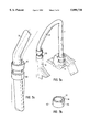
- FIG. 4 is a perspective view of a rollover protection device according to another preferred embodiment of the present invention.
- FIG. 5 is a front view of the rollover device of FIG. 4;
- FIG. 6 is a sectional view of the rollover device of FIG. 4.
- FIG. 7 is a perspective elevated view of the rollover bars according to the present invention installed in a vehicle in the normal condition.
- a rollover protection device contains two rollover bars 1, 2 which are arranged behind the two seats 3 and 4 of a convertible (see FIGS. 1 and 7). With respect to a longitudinal vehicle axis, the two rollover bars 1, 2 are arranged and constructed approximately mirror-symmetrically so that the following description will describe only one of the rollover bars (specifically the rollover bar 1 which is on the right with respect to the vehicle), but applies to both rollover bars.
- the rollover bar 1 (see FIG. 1) contains two spaced legs 6, 7 which, in its installed position, extend from a connection piece 5 in parallel downward, the leg 6 which is on the outside of the vehicle being longer than the leg 7 which is on the inside and extending farther downward.
- the legs 6, 7 are each accommodated and disposed in a receiving tube 8, 9 corresponding to the respective leg length.
- the receiving tube 9 which is on the vehicle interior is contained in a bearing block 17 on the vehicle body.
- the receiving tube 8 which is on the outside of the vehicle projects on the top and on the bottom beyond the adjacent shorter receiving tube 9.
- the inside cross-section or inside diameter of the two receiving tubes 8, 9 is larger than the outside cross-section or outside diameter of the respective, for example, tube-shaped or rod-shaped, bending-resistant (for example, made of steel) legs 6, 7.
- the legs 6, 7 preferably have a round cross-section so that they can be accommodated with a play to the inside wall of the receiving tubes 8, 9 and may be made, for example, of steel.
- the absorber element 10 is a ring-shaped body with an eccentrically arranged longitudinal bore or passage bore 11. In the embodiment shown in FIGS. 1-3, it has an outer ring 12 and an inner ring 13 which is arranged eccentrically in the outer ring 12 and is connected with the outer ring 12 by means of several webs 14 so that several hollow spaces 15 or longitudinal passages are provided between the outer ring 12 and the inner ring 13.
- the absorber element 10 is made of an elastomeric material, such as rubber or plastic.
- the inside diameter of the inner ring 13 is adapted to the outside diameter of the leg 6, 7 such that the absorber element 10 is disposed in a non-displaceable manner on the leg 6, 7.
- the absorber element 10 can be pushed onto the leg 6, 7 and can be fixed on the leg 6, 7 by means of a screw or an adhesive, and can be pressed on or vulcanized on.
- the outside diameter of the absorber element 10 is adapted such to the inside diameter of the receiving tube 8, 9 that the absorber element 10 can be elastically and firmly fitted into the receiving tube 8, 9.
- the receiving tube 8, 9 and the absorber element 10 may also have an elliptic or any other suitable cross-section.
- Each absorber element 10 is arranged to be aligned such that the inner ring 13 or the longitudinal bore 11 is displaced eccentrically toward the front in the longitudinal direction of the vehicle. This means that the wall thickness of the absorber element 10, measured from the interior side of the inner ring 13 to the exterior side of the outer ring 12, in a vertical sectional plane in the longitudinal direction is smaller on the forward side (arrow A in FIG. 2b) than on the opposite rearward side (arrow B).
- the leg 6, 7 can move radially or generally in a horizontal plane in the absorber element 10 relative to the outer ring 12 and thus to the receiving tube 8, 9 until it comes to rest on the wall of the receiving tube 8, 9.
- the movement and deformation path is the largest in the longitudinal direction of the vehicle.
- the leg 6, 7 can also move laterally until it comes to rest against the receiving tube 8, 9. The movement possibility is determined by the damping capacity of the material of the webs 14 as the result of their number, size, distribution and deformation characteristics.
- a tilting movement of the leg 6, 7 in the absorber element 10 may also take place, that is, a swivelling of the longitudinal axis of the leg 6, 7 and of the inner ring 13 relative to the outer ring 12 (see, for example, FIG. 3).
- the absorber element 10 may be a combination bearing which has an outer ring and an inner ring made of a hard and essentially non-deformable material, such as metal or hard plastic, which are connected with one another by elastically deformable webs.
- a covering surrounds the two receiving tubes 8, 9 and the bearing block 17 (see FIGS. 1 and 7).
- the area of the installed rollover bar 1, 2, which is outside the two receiving tubes 8, 9 (that is, essentially the connection part 5, which can be of a U-shape or similar shape, and an upper section of the leg 7) is provided with a cushioning or padding 16 which is constructed as a foamed-material casing.
- FIGS. 3a-c show a rollover bar which is deflected to the rear in the longitudinal direction of the vehicle (the undeflected normal condition is illustrated by a broken line).
- FIG. 3c clearly shows the deformed absorber element 10 (leg not shown) whose inner ring 13, while the webs 14 are deformed, has been displaced toward the rear relative to the outer ring 12.
- FIGS. 4-6 show another embodiment of the present invention, in which the absorber element comprises an outer tube 10' with an inner elastic sleeve 20 disposed on an interior side.
- the tube 10' may be made of plastic, or metal, such as aluminum.
- the elastic sleeve 20 (shown in hatched lines) is made of an elastic material, preferably a foam rubber.
- the elastic sleeve 20 and the tube 10' when made of metal, thus form an elastomer-metal combination element.
- the elastic sleeve 20 preferably extends the full length of the tube 10', but may extend only part of the length of the tube 10'. In an assembled position, the inner elastic sleeve 20 is disposed between the tube 10 and one of the legs 6', 7'.
- the exposed portion of the rollover bar is covered with a cushioning or padding 16'.
- the absorber element consisting of the tube 10' and the elastic sleeve 20 may be attached to the leg 6', 7', for example by vulcanization.
- the legs 6', 7' are received by the receiving tubes 8', and are fastened thereto by threaded connectors 21, such as bolts or screws, which are placed through respective holes 22 of the receiving tubes 8' and threaded into respective threaded receptacles 19 in the tube 10'.
- the elastic deformability of the elastic sleeve 20 provides the damping effect which permits a limited relative movement of the rollover bar (legs 6', 7') with respect to the vehicle-fixed structure (receiving tubes 8').
Abstract
A rollover protection device for a motor vehicle has at least one rollover bar which is disposed on a vehicle-fixed structure with a deformable bearing permitting limited movement of the rollover bar relative to the vehicle-fixed structure. In particular, the bearing is elastically deformable and may have at least one deformable, particularly elastically deformable, absorber element which disposes legs of the rollover bar in receiving tubes.
Description
This invention relates to a rollover protection device for a motor vehicle.
In the case of convertibles, it is known to provide a rollover protection device in the form of a rollover bar which, in the case of an accident and particularly in the case of an overturning of the vehicle, forms a firm structure which protects the occupants. Rollover bars of this type are usually mounted rigidly to the vehicle body or have a folding mechanism which folds them upwards, from a lowered inoperative position, as required, into an active safety position in which the bar can then be held in a rigidly locked manner.
Although, for reasons of stability, a rigid arrangement of the rollover bar is desirable, it can have disadvantageous effects if, during an accident, a vehicle occupant hits his head on the rollover bar and is injured by it.
It is therefore an object of the present invention to improve a rollover protection device of the initially mentioned type such that its injury potential is reduced, particularly with respect to a head impact.
This and other objects have been achieved according to the present invention by providing a rollover protection device for a motor vehicle, comprising at least one rollover bar which is disposed on a vehicle-fixed structure with a deformable bearing which permits a limited relative movement of the rollover bar with respect to the vehicle-fixed structure.
By means of the deformable bearing of the rollover bar on a vehicle-fixed structure, when force is introduced, the rollover bar can move by a limited path relative to the fixed body structure before it rests against the fixed body structure in a rigid and firm manner. In this case, for example, in the case of the impact of a vehicle occupant's head, the HIC (head-injury-criterion) values can be significantly lowered in contrast to a non-resilient arrangement. The bearing absorbs the energy introduced into the rollover bar and therefore has a damping effect. Such a deformation can take place plastically; thus, for example, an aluminum honeycomb construction can be used as the deformable component for the bearing. Alternatively, the deformable component for the bearing may be made of an elastic material such as rubber, foam rubber, or an elastic polymer, which may be vulcanized for added strength. As the result of the deformable bearing, an occurring force can be reduced uniquely by deforming work. According to one advantageous embodiment, the bearing permits a relative movement in all directions, in which case the largest possibility of movement is provided essentially in the longitudinal direction of the vehicle for the possibility of an impact of the human body.
According to another advantageous embodiment, an elastically deformable bearing which absorbs the moving energy of the rollover bar and can then deform back into its starting position when the rollover bar is unloaded is provided. This embodiment is particularly advantageous in order to offer a bearing to the rollover bar which is resilient to a limited extent in the case of a repeated effect of force on the rollover bar.
Advantageously, the bearing comprises an absorber element which is constructed to be deformable and particularly plastically or elastically deformable and which by deformation can partially or completely absorb the movement energy introduced by an impact on to the rollover bar.
The rollover bar can consist of a tube, a rod or a profile construction and can be made of steel or a comparable firm material and extend essentially along the whole vehicle width. Likewise, for example, a U-shaped rollover bar can be provided approximately behind each seat whose two legs, while pointing downward, are accommodated in two receiving tubes fixedly mounted on the vehicle and are disposed therein by means of the absorber elements. In the normal condition, the absorber elements hold the rollover bar or the two legs away from the interior wall of the respective receiving tube and permit the above-described shifting of the rollover bar until the legs come to rest on the receiving tube and/or in the axial direction on a fixed stop.
The bearing may have one or several absorber elements on each leg. The absorber element may have a spring arrangement which holds the leg under spring prestress in the receiving tube and against whose force the rollover bar can be elastically deflected. On the other hand, the absorber element may have a reversibly or irreversibly deformable structure, such as a honeycomb structure, which reduces introduced movement energy by deformation. Advantageously, the absorber element is ring-shaped and is fitted between the leg and the receiving tube, in which case the leg is then received in an approximately central longitudinal bore or molded-in recess. Preferably, the leg is eccentrically accommodated in the receiving tube such that, in a preferred direction, it is provided with a movement path which is as large as possible. For this purpose, in one advantageous embodiment, the longitudinal bore or recess is eccentrically displaced in the ring-shaped absorber element so that, in the installed position of the absorber element, the leg is arranged closer to the forward wall section of the receiving tube (viewed in the driving direction).
In another advantageous embodiment, the absorber element contains an outer ring for the contact against the interior wall of the receiving tube and an inner ring for the firm holding of the leg. The two rings are flexibly connected with one another by means of deforming webs which also determine the deforming capacity of the absorber element.
The absorber element may advantageously be made of an elastomeric material (such as rubber or an elastomeric plastic material with comparable characteristics). It may also be combined with other materials as well as with metal in order to advantageously combine stability and elastic characteristics.
A leg of the rollover bar can be constructed to be lengthened in order to offer to the rollover bar the required rigid bearing when being placed against the receiving tube. Depending on the arrangement of the absorber element with respect to the leg and the movement possibility of the leg in the receiving tube, different displacement and swivelling movements of the rollover bar may be permitted.
Advantageously, an additional securing of the rollover bar against a removal or an unintended pulling-out in the case of a turnover can be provided. This safety device can be constructed as a lock or catch engaging on a recess of the leg.
Other objects, advantages and novel features of the present invention will become apparent from the following detailed description of the invention when considered in conjunction with the accompanying drawings.
FIG. 1 is a perspective elevated exploded view of a rollover protection device according to one preferred embodiment of the present invention;
FIGS. 2a-c are perspective elevated views of the rollover device of FIG. 1 with its bearing in the normal condition;
FIGS. 3a-c are perspective elevated views of the rollover device of FIG. 1 with its bearing in a deflected condition;
FIG. 4 is a perspective view of a rollover protection device according to another preferred embodiment of the present invention;
FIG. 5 is a front view of the rollover device of FIG. 4;
FIG. 6 is a sectional view of the rollover device of FIG. 4; and
FIG. 7 is a perspective elevated view of the rollover bars according to the present invention installed in a vehicle in the normal condition.
A rollover protection device according to the invention contains two rollover bars 1, 2 which are arranged behind the two seats 3 and 4 of a convertible (see FIGS. 1 and 7). With respect to a longitudinal vehicle axis, the two rollover bars 1, 2 are arranged and constructed approximately mirror-symmetrically so that the following description will describe only one of the rollover bars (specifically the rollover bar 1 which is on the right with respect to the vehicle), but applies to both rollover bars.
The rollover bar 1 (see FIG. 1) contains two spaced legs 6, 7 which, in its installed position, extend from a connection piece 5 in parallel downward, the leg 6 which is on the outside of the vehicle being longer than the leg 7 which is on the inside and extending farther downward. The legs 6, 7 are each accommodated and disposed in a receiving tube 8, 9 corresponding to the respective leg length. The receiving tube 9 which is on the vehicle interior is contained in a bearing block 17 on the vehicle body. The receiving tube 8 which is on the outside of the vehicle projects on the top and on the bottom beyond the adjacent shorter receiving tube 9.
The inside cross-section or inside diameter of the two receiving tubes 8, 9 is larger than the outside cross-section or outside diameter of the respective, for example, tube-shaped or rod-shaped, bending-resistant (for example, made of steel) legs 6, 7. The legs 6, 7 preferably have a round cross-section so that they can be accommodated with a play to the inside wall of the receiving tubes 8, 9 and may be made, for example, of steel.
In a mutually spaced manner, two absorber elements 10 are mounted on each leg 6, 7, by means of which absorber elements 10 the rollover bar 1 is disposed in the receiving tubes 8, 9 spaced away from the walls of the tube.
The absorber element 10 is a ring-shaped body with an eccentrically arranged longitudinal bore or passage bore 11. In the embodiment shown in FIGS. 1-3, it has an outer ring 12 and an inner ring 13 which is arranged eccentrically in the outer ring 12 and is connected with the outer ring 12 by means of several webs 14 so that several hollow spaces 15 or longitudinal passages are provided between the outer ring 12 and the inner ring 13. The absorber element 10 is made of an elastomeric material, such as rubber or plastic. The inside diameter of the inner ring 13 is adapted to the outside diameter of the leg 6, 7 such that the absorber element 10 is disposed in a non-displaceable manner on the leg 6, 7. For this purpose, the absorber element 10 can be pushed onto the leg 6, 7 and can be fixed on the leg 6, 7 by means of a screw or an adhesive, and can be pressed on or vulcanized on.
The outside diameter of the absorber element 10 is adapted such to the inside diameter of the receiving tube 8, 9 that the absorber element 10 can be elastically and firmly fitted into the receiving tube 8, 9. Instead of having the shown circular cross-section, the receiving tube 8, 9 and the absorber element 10 may also have an elliptic or any other suitable cross-section.
Each absorber element 10 is arranged to be aligned such that the inner ring 13 or the longitudinal bore 11 is displaced eccentrically toward the front in the longitudinal direction of the vehicle. This means that the wall thickness of the absorber element 10, measured from the interior side of the inner ring 13 to the exterior side of the outer ring 12, in a vertical sectional plane in the longitudinal direction is smaller on the forward side (arrow A in FIG. 2b) than on the opposite rearward side (arrow B).
By means of the elastic suspension of the inner ring 13 on the outer ring 12 by way of the webs 14, in the case of a corresponding introduction of force, the leg 6, 7 can move radially or generally in a horizontal plane in the absorber element 10 relative to the outer ring 12 and thus to the receiving tube 8, 9 until it comes to rest on the wall of the receiving tube 8, 9. According to the eccentric arrangement of the absorber element 10 and of the leg 6, 7 in the absorber element 10, the movement and deformation path is the largest in the longitudinal direction of the vehicle. However, the leg 6, 7 can also move laterally until it comes to rest against the receiving tube 8, 9. The movement possibility is determined by the damping capacity of the material of the webs 14 as the result of their number, size, distribution and deformation characteristics. As a function of the bearing arrangement (length, mutual spacing and arrangement of the absorber elements), a tilting movement of the leg 6, 7 in the absorber element 10 may also take place, that is, a swivelling of the longitudinal axis of the leg 6, 7 and of the inner ring 13 relative to the outer ring 12 (see, for example, FIG. 3).
The absorber element 10 may be a combination bearing which has an outer ring and an inner ring made of a hard and essentially non-deformable material, such as metal or hard plastic, which are connected with one another by elastically deformable webs.
In the case of a vehicle rollover, in which the rollover bar 1, 2 must support the vehicle weight, a significant force component is introduced in the longitudinal direction of the legs 6, 7 (that is vertically) into the rollover bar 1, 2. This rollover bar 1, 2 is displaced axially by a defined distance, for example, by 5 mm, to an axial stop (not shown) on the receiving tube 8, 9 and is rigidly supported thereon. The elastic webs 14 can deform corresponding to this axial movement.
A covering surrounds the two receiving tubes 8, 9 and the bearing block 17 (see FIGS. 1 and 7). The area of the installed rollover bar 1, 2, which is outside the two receiving tubes 8, 9 (that is, essentially the connection part 5, which can be of a U-shape or similar shape, and an upper section of the leg 7) is provided with a cushioning or padding 16 which is constructed as a foamed-material casing.
FIGS. 3a-c show a rollover bar which is deflected to the rear in the longitudinal direction of the vehicle (the undeflected normal condition is illustrated by a broken line). FIG. 3c clearly shows the deformed absorber element 10 (leg not shown) whose inner ring 13, while the webs 14 are deformed, has been displaced toward the rear relative to the outer ring 12.
FIGS. 4-6 show another embodiment of the present invention, in which the absorber element comprises an outer tube 10' with an inner elastic sleeve 20 disposed on an interior side. The tube 10' may be made of plastic, or metal, such as aluminum. The elastic sleeve 20 (shown in hatched lines) is made of an elastic material, preferably a foam rubber. The elastic sleeve 20 and the tube 10', when made of metal, thus form an elastomer-metal combination element. The elastic sleeve 20 preferably extends the full length of the tube 10', but may extend only part of the length of the tube 10'. In an assembled position, the inner elastic sleeve 20 is disposed between the tube 10 and one of the legs 6', 7'. The exposed portion of the rollover bar is covered with a cushioning or padding 16'. The absorber element consisting of the tube 10' and the elastic sleeve 20 may be attached to the leg 6', 7', for example by vulcanization. The legs 6', 7' are received by the receiving tubes 8', and are fastened thereto by threaded connectors 21, such as bolts or screws, which are placed through respective holes 22 of the receiving tubes 8' and threaded into respective threaded receptacles 19 in the tube 10'. The elastic deformability of the elastic sleeve 20 provides the damping effect which permits a limited relative movement of the rollover bar (legs 6', 7') with respect to the vehicle-fixed structure (receiving tubes 8').
Although the invention has been described and illustrated in detail, it is to be clearly understood that the same is by way of illustration and example, and is not to be taken by way of limitation. The spirit and scope of the present invention are to be limited only by the terms of the appended claims.
Claims (19)
1. A rollover protection device for a motor vehicle, comprising at least one rollover bar having two legs which are disposed in two vehicle-fixed receiving tubes via at least two deformable absorber elements which permit a limited relative movement of the rollover bar with respect to the vehicle-fixed receiving tubes, the legs being eccentrically positioned in the absorber elements with respect to the receiving tubes.
2. A rollover protection device according to claim 1, wherein the absorber elements are elastically deformable.
3. A rollover protection device according to claim 1, wherein, in an undeformed position, said legs are held by said deformable absorber elements away from walls of said receiving tubes.
4. A rollover protection device according to claim 3, wherein the deformable absorber elements are fastened by screws on the legs or the receiving tubes.
5. A rollover protection device according to claim 3, wherein the deformable absorber elements are vulcanized onto the legs.
6. A rollover protection device according to claim 1, wherein the deformable absorber elements surround the legs in a ring-shaped manner.
7. A rollover protection device according to claim 1, wherein the absorber elements are made of an elastomeric material.
8. A rollover protection device according to claim 1, wherein the absorber elements are elastomer-metal combination elements.
9. A rollover protection device according to claim 1, wherein the maximum moving paths of the legs in the deformable absorber elements are aligned approximately in the longitudinal direction of the vehicle.
10. A rollover protection device according to claim 1, wherein one of said two legs of the rollover bar is lengthened relative to the other of said two legs of the rollover bar.
11. A rollover protection device according to claim 1, wherein the two legs are connected by a free section of the rollover bar which is provided with a cushion.
12. A rollover protection device according to claim 11, wherein the cushion is a foamed material which encases the rollover bar.
13. A rollover protection device according to claim 1, wherein two of said deformable absorber elements are provided on each of said legs.
14. A rollover protection device according to claim 1, wherein said motor vehicle is a convertible with two seats, and wherein said at least one rollover bar comprises two rollover bars which are arranged approximately behind the two seats.
15. A rollover protection device for a motor vehicle, comprising at least one rollover bar which is disposed on a vehicle-fixed structure with a deformable absorber element which permits a limited relative movement of the rollover bar with respect to the vehicle-fixed structure, wherein the absorber element has an outer ring and an inner ring and the two rings are connected with one another by webs.
16. A rollover protection device for a motor vehicle, comprising:
a rollover bar comprising at least one leg;
a vehicle-fixed receiving tube configured to receive the rollover bar; and
an elastically deformable ring-shaped absorber element interposed between the rollover bar and the vehicle-fixed receiving tube to permit a limited relative movement of the rollover bar with respect to the vehicle-fixed receiving tube, the absorber element holding the leg at a radial distance from the receiving tube, the absorber element including an outer ring and an inner ring arranged inside said outer ring, the outer ring being radially spaced apart from the inner ring with a plurality of webs connecting the outer ring and the inner ring.
17. A rollover protection device according to claim 16, wherein said inner ring is arranged eccentrically with respect to said outer ring.
18. A rollover protection device according to claim 16, wherein an outer periphery of said outer ring engages an inner periphery of said receiving tube, and wherein an inner periphery of said inner ring engages an outer periphery of said leg.
19. A rollover protection device according to claim 16, wherein said deformable absorber element comprises a foam rubber sleeve.
Applications Claiming Priority (2)
| Application Number | Priority Date | Filing Date | Title |
|---|---|---|---|
| DE19604423A DE19604423A1 (en) | 1996-02-07 | 1996-02-07 | Rollover protection for a motor vehicle |
| DE19604423.5 | 1996-02-07 |
Publications (1)
| Publication Number | Publication Date |
|---|---|
| US5890738A true US5890738A (en) | 1999-04-06 |
Family
ID=7784750
Family Applications (1)
| Application Number | Title | Priority Date | Filing Date |
|---|---|---|---|
| US08/797,791 Expired - Lifetime US5890738A (en) | 1996-02-07 | 1997-02-07 | Rollover bar with deformable bearing |
Country Status (3)
| Country | Link |
|---|---|
| US (1) | US5890738A (en) |
| EP (1) | EP0788932B1 (en) |
| DE (2) | DE19604423A1 (en) |
Cited By (25)
| Publication number | Priority date | Publication date | Assignee | Title |
|---|---|---|---|---|
| WO2002002387A3 (en) * | 2000-07-05 | 2002-06-06 | Sika Corp | Reinforcing member for interfitting channels |
| US20030042722A1 (en) * | 2001-08-31 | 2003-03-06 | Klaus Hovelmann | Rollover protection sysem for motor vehicles with predetermined deformation point |
| US6572145B1 (en) * | 1999-03-16 | 2003-06-03 | Societe Europeenne De Brevets Automobiles | Rollbar for convertible vehicle with folding roof |
| US20030218352A1 (en) * | 2002-03-06 | 2003-11-27 | Webasto Vehicle Systems International Gmbh | Cabriolet vehicle with a convertible top hatch and a roll bar which can be coupled to it |
| US20040108701A1 (en) * | 2002-12-05 | 2004-06-10 | Richard Kleinhoffer | Adjustable three-piece hydroformed sport bar |
| EP1134129A3 (en) * | 2000-03-15 | 2004-07-21 | ISE Innomotive Systems Europe GmbH | Device for holding the roll bar of a roll bar protection system |
| EP1273484A3 (en) * | 2001-07-04 | 2004-09-22 | ISE Innomotive Systems Europe GmbH | Roll bar protection system for motor vehicles |
| US20050140129A1 (en) * | 2003-12-24 | 2005-06-30 | Mazda Motor Corporation | Roll bar structure of vehicle |
| US20050156422A1 (en) * | 2004-01-16 | 2005-07-21 | Same Deutz-Fahr Group S.P.A. | Sprung roll bar |
| US20050280253A1 (en) * | 2004-06-16 | 2005-12-22 | Gerard Queveau | Safety device used in case a vehicle rolls over |
| US20060170203A1 (en) * | 2005-02-02 | 2006-08-03 | Reinhard Nowack | Vehicle rollover protection system with a roll bar, whose top piece is rounded in U-shape |
| US20070200330A1 (en) * | 2006-02-24 | 2007-08-30 | Dan Tang | Occupant Safety Device For Roof Reinforcement |
| US20070200400A1 (en) * | 2006-02-24 | 2007-08-30 | Dan Tang | Support Structure For Roof Reinforcement |
| US20080084054A1 (en) * | 2006-10-10 | 2008-04-10 | Automotive Group Ise Innomotive Systems Europe Gmbh | Rollover-protection system for motor vehicles with at least one actively deployable roll bar |
| US20080122210A1 (en) * | 2006-11-24 | 2008-05-29 | Automotive Group Ise Innomotive Systems Europe Gmbh | Rollover protection system for motor vehicles with an actively deployable rollover body |
| US20080197613A1 (en) * | 2007-02-12 | 2008-08-21 | Automotive Group Ise Innomotive Systems | Rollover protection system for motor vehicles with a sensor-controlled actively deployable rollover body |
| US20080203717A1 (en) * | 2007-02-03 | 2008-08-28 | Automotive Group Ise Innomotive Systems Europe Gmbh | Rollover protection system for motor vehicles with an actively deployable rollover body |
| US20090096199A1 (en) * | 2006-02-24 | 2009-04-16 | Ford Global Technologies, Llc | Reinforcement for a vehicle having a pillared roof |
| US20090095555A1 (en) * | 2007-03-23 | 2009-04-16 | Automotive Group Ise Innomotive Systems Europe Gmbh | Rollover protection system for motor vehicles with a sensor-controlled actively deployable rollover body |
| US20090102175A1 (en) * | 2006-02-24 | 2009-04-23 | Ford Global Technologies, Llc. | Occupant safety device for roof reinforcement |
| US20150061269A1 (en) * | 2012-05-10 | 2015-03-05 | Bayerische Motoren Werke Aktiengesellschaft | Motor Vehicle Having a Rollover Protection System |
| US9573547B2 (en) | 2012-02-28 | 2017-02-21 | Ag-Tech Industries Limited | Flexible impact protection |
| US20190315304A1 (en) * | 2018-04-11 | 2019-10-17 | Ford Global Technologies, Llc | Roof mounted seat support airbag |
| EP3560771A1 (en) | 2018-04-24 | 2019-10-30 | David Robertson | A roll-over protection apparatus |
| US11447087B2 (en) * | 2018-03-09 | 2022-09-20 | Doosan Infracore Co., Ltd. | Canopy assembly of construction machinery |
Families Citing this family (15)
| Publication number | Priority date | Publication date | Assignee | Title |
|---|---|---|---|---|
| EP0904991B1 (en) * | 1997-09-24 | 2003-12-03 | ISE Innomotive Systems Europe GmbH | Rollover protection system for motor vehicles without a fixed rigid roof and method of producing said system |
| DE19931224A1 (en) * | 1999-07-06 | 2001-01-11 | Bayerische Motoren Werke Ag | Rollover protection system for a vehicle |
| DE10140240A1 (en) * | 2001-08-22 | 2003-03-13 | Webasto Vehicle Sys Int Gmbh | Vehicle with a roof that can be opened |
| DE102005051143B3 (en) * | 2005-10-26 | 2006-10-26 | Ise Innomotive Systems Europe Gmbh | Rolling protection system for vehicles comprises a time part for coupling with a self-retaining central unlocking unit of an unlocking device |
| DE102005059910B3 (en) | 2005-12-15 | 2007-04-12 | Automotive Group Ise Innomotive Systems Europe Gmbh | Rollover protective system for a vehicle comprises roll bars each having side parts hinged with one end in bearings in a holder and folding with the free end |
| DE102006001579B3 (en) * | 2006-01-12 | 2007-03-01 | Ise Innomotive Systems Europe Gmbh | Roll-over protection system for e.g. sports car, has additional guide component with peripheral round running guide surface for direct bushing-free attachment to inner wall of associated guide opening |
| DE102006002941A1 (en) * | 2006-01-21 | 2007-08-02 | Automotive Group Ise Innomotive Systems Europe Gmbh | Rollover protection tube for motor vehicle has u-shaped tube formed by hydroforming with heat applied in areas of greatest deformation during bending |
| DE102006006659B3 (en) * | 2006-02-14 | 2007-06-21 | Automotive Group Ise Innomotive Systems Europe Gmbh | Roll-over protection system for motor vehicle e.g. sports car, has rotary latches and mechanical coupling of retaining devices attached in guide section, and common actuator fastened at section and directly coupled to mechanical coupling |
| DE102006006658B3 (en) * | 2006-02-14 | 2007-05-03 | Automotive Group Ise Innomotive Systems Europe Gmbh | Roll-over bar protection system for motor vehicles, has wear protectives which are formed glass breaking and rollover bar protection system has active arrangeable roll over bar which is taken up in bracket fixed into vehicle |
| DE102006015756B4 (en) * | 2006-04-04 | 2009-01-22 | Automotive Group Ise Innomotive Systems Europe Gmbh | Rollover protection system for motor vehicles with at least one actively deployable roll bar |
| DE102006023502B3 (en) * | 2006-05-18 | 2008-02-07 | Automotive Group Ise Innomotive Systems Europe Gmbh | Rollover protection system for motor vehicles with at least one actively deployable rollover body |
| DE102006024332B3 (en) * | 2006-05-24 | 2008-01-31 | Automotive Group Ise Innomotive Systems Europe Gmbh | Rollover protection system for motor vehicles, has rollover body, adjustable in mounting plate, which is fixed to vehicle, where rollover body is held in normal condition, by holding device in lower and idle position |
| DE102006038757A1 (en) * | 2006-08-17 | 2008-02-28 | Automotive Group Ise Innomotive Systems Europe Gmbh | Rollover protection system for motor vehicles with at least one roll bar |
| EP1955907B8 (en) * | 2007-02-12 | 2010-02-17 | ISE Automotive GmbH | System for roll-over protection with roll bar for motor vehicles |
| DE102014113619A1 (en) * | 2014-09-22 | 2016-03-24 | Dr. Ing. H.C. F. Porsche Aktiengesellschaft | Roll bar arrangement for a motor vehicle |
Citations (10)
| Publication number | Priority date | Publication date | Assignee | Title |
|---|---|---|---|---|
| US3203728A (en) * | 1962-10-04 | 1965-08-31 | Concrete Steel Corp | Mount for tractor canopy |
| US3353852A (en) * | 1965-07-15 | 1967-11-21 | Concrete Steel Corp | Mount for tractor canopy post |
| US3612581A (en) * | 1969-11-18 | 1971-10-12 | Fleco Corp | Canopy mount |
| US3704031A (en) * | 1970-04-16 | 1972-11-28 | Howard F Confer | Protection apparatus for a vehicle |
| US3754315A (en) * | 1972-02-24 | 1973-08-28 | Int Harvester Co | Method and means for attaching protection structure to a vehicle frame |
| US4032187A (en) * | 1975-12-22 | 1977-06-28 | Allis-Chalmers Corporation | Energy absorbing joint for protective frame |
| EP0189819A2 (en) * | 1985-01-26 | 1986-08-06 | Bayerische Motoren Werke Aktiengesellschaft, Patentabteilung AJ-3 | Motor vehicle with an open body |
| DE4314538A1 (en) * | 1993-05-03 | 1994-11-10 | Bayerische Motoren Werke Ag | Extending roll-over frame for open vehicle |
| WO1995003952A1 (en) * | 1993-08-03 | 1995-02-09 | Itt Automotive Europe Gmbh | Roll bar device with internal guide and external guide |
| EP0657327A1 (en) * | 1993-12-13 | 1995-06-14 | ITT Automotive Europe GmbH | Guide bush for a roll bar |
-
1996
- 1996-02-07 DE DE19604423A patent/DE19604423A1/en not_active Withdrawn
-
1997
- 1997-01-23 DE DE59701613T patent/DE59701613D1/en not_active Expired - Lifetime
- 1997-01-23 EP EP97100990A patent/EP0788932B1/en not_active Expired - Lifetime
- 1997-02-07 US US08/797,791 patent/US5890738A/en not_active Expired - Lifetime
Patent Citations (10)
| Publication number | Priority date | Publication date | Assignee | Title |
|---|---|---|---|---|
| US3203728A (en) * | 1962-10-04 | 1965-08-31 | Concrete Steel Corp | Mount for tractor canopy |
| US3353852A (en) * | 1965-07-15 | 1967-11-21 | Concrete Steel Corp | Mount for tractor canopy post |
| US3612581A (en) * | 1969-11-18 | 1971-10-12 | Fleco Corp | Canopy mount |
| US3704031A (en) * | 1970-04-16 | 1972-11-28 | Howard F Confer | Protection apparatus for a vehicle |
| US3754315A (en) * | 1972-02-24 | 1973-08-28 | Int Harvester Co | Method and means for attaching protection structure to a vehicle frame |
| US4032187A (en) * | 1975-12-22 | 1977-06-28 | Allis-Chalmers Corporation | Energy absorbing joint for protective frame |
| EP0189819A2 (en) * | 1985-01-26 | 1986-08-06 | Bayerische Motoren Werke Aktiengesellschaft, Patentabteilung AJ-3 | Motor vehicle with an open body |
| DE4314538A1 (en) * | 1993-05-03 | 1994-11-10 | Bayerische Motoren Werke Ag | Extending roll-over frame for open vehicle |
| WO1995003952A1 (en) * | 1993-08-03 | 1995-02-09 | Itt Automotive Europe Gmbh | Roll bar device with internal guide and external guide |
| EP0657327A1 (en) * | 1993-12-13 | 1995-06-14 | ITT Automotive Europe GmbH | Guide bush for a roll bar |
Cited By (38)
| Publication number | Priority date | Publication date | Assignee | Title |
|---|---|---|---|---|
| US6572145B1 (en) * | 1999-03-16 | 2003-06-03 | Societe Europeenne De Brevets Automobiles | Rollbar for convertible vehicle with folding roof |
| EP1134129A3 (en) * | 2000-03-15 | 2004-07-21 | ISE Innomotive Systems Europe GmbH | Device for holding the roll bar of a roll bar protection system |
| US6523857B1 (en) * | 2000-07-05 | 2003-02-25 | Sika Corporation | Reinforcing member for interfitting channels |
| WO2002002387A3 (en) * | 2000-07-05 | 2002-06-06 | Sika Corp | Reinforcing member for interfitting channels |
| JP2004516971A (en) * | 2000-07-05 | 2004-06-10 | シカ コーポレーション | Reinforcement members for interfitting channels |
| EP1273484A3 (en) * | 2001-07-04 | 2004-09-22 | ISE Innomotive Systems Europe GmbH | Roll bar protection system for motor vehicles |
| US20030042722A1 (en) * | 2001-08-31 | 2003-03-06 | Klaus Hovelmann | Rollover protection sysem for motor vehicles with predetermined deformation point |
| US6817628B2 (en) * | 2001-08-31 | 2004-11-16 | Ise Innomotive Systems | Rollover protection sysem for motor vehicles with predetermined deformation point |
| US6834908B2 (en) * | 2002-03-06 | 2004-12-28 | Webasto Vehicle Systems International Gmbh | Cabriolet vehicle with a convertible top hatch and a roll bar which can be coupled to it |
| US20030218352A1 (en) * | 2002-03-06 | 2003-11-27 | Webasto Vehicle Systems International Gmbh | Cabriolet vehicle with a convertible top hatch and a roll bar which can be coupled to it |
| US20040108701A1 (en) * | 2002-12-05 | 2004-06-10 | Richard Kleinhoffer | Adjustable three-piece hydroformed sport bar |
| US7021658B2 (en) * | 2002-12-05 | 2006-04-04 | Daimlerchrysler Corporation | Adjustable three-piece hydroformed sport bar |
| US20050140129A1 (en) * | 2003-12-24 | 2005-06-30 | Mazda Motor Corporation | Roll bar structure of vehicle |
| US7325832B2 (en) * | 2003-12-24 | 2008-02-05 | Mazda Motor Corporation | Roll bar structure of vehicle |
| US20050156422A1 (en) * | 2004-01-16 | 2005-07-21 | Same Deutz-Fahr Group S.P.A. | Sprung roll bar |
| US7261321B2 (en) * | 2004-01-16 | 2007-08-28 | Same Deutz-Fahr Group S.P.A. | Sprung roll bar |
| US20050280253A1 (en) * | 2004-06-16 | 2005-12-22 | Gerard Queveau | Safety device used in case a vehicle rolls over |
| US7341278B2 (en) * | 2004-06-21 | 2008-03-11 | Heuliez | Safety device used in case a vehicle rolls over |
| US20060170203A1 (en) * | 2005-02-02 | 2006-08-03 | Reinhard Nowack | Vehicle rollover protection system with a roll bar, whose top piece is rounded in U-shape |
| US7458608B2 (en) * | 2005-02-02 | 2008-12-02 | Ise Innovative Systems Europe Gmbh | Vehicle rollover protection system with a roll bar, whose top piece is rounded in U-shape |
| US20070200400A1 (en) * | 2006-02-24 | 2007-08-30 | Dan Tang | Support Structure For Roof Reinforcement |
| US7585023B2 (en) * | 2006-02-24 | 2009-09-08 | Ford Global Technologies, Llc | Support structure for roof reinforcement |
| US7744125B2 (en) | 2006-02-24 | 2010-06-29 | Ford Global Technologies, Llc | Occupant safety device for roof reinforcement |
| US20090102175A1 (en) * | 2006-02-24 | 2009-04-23 | Ford Global Technologies, Llc. | Occupant safety device for roof reinforcement |
| US20090096199A1 (en) * | 2006-02-24 | 2009-04-16 | Ford Global Technologies, Llc | Reinforcement for a vehicle having a pillared roof |
| US20070200330A1 (en) * | 2006-02-24 | 2007-08-30 | Dan Tang | Occupant Safety Device For Roof Reinforcement |
| US20080084054A1 (en) * | 2006-10-10 | 2008-04-10 | Automotive Group Ise Innomotive Systems Europe Gmbh | Rollover-protection system for motor vehicles with at least one actively deployable roll bar |
| US20080122210A1 (en) * | 2006-11-24 | 2008-05-29 | Automotive Group Ise Innomotive Systems Europe Gmbh | Rollover protection system for motor vehicles with an actively deployable rollover body |
| US20080203717A1 (en) * | 2007-02-03 | 2008-08-28 | Automotive Group Ise Innomotive Systems Europe Gmbh | Rollover protection system for motor vehicles with an actively deployable rollover body |
| US20080197613A1 (en) * | 2007-02-12 | 2008-08-21 | Automotive Group Ise Innomotive Systems | Rollover protection system for motor vehicles with a sensor-controlled actively deployable rollover body |
| US20090095555A1 (en) * | 2007-03-23 | 2009-04-16 | Automotive Group Ise Innomotive Systems Europe Gmbh | Rollover protection system for motor vehicles with a sensor-controlled actively deployable rollover body |
| US9573547B2 (en) | 2012-02-28 | 2017-02-21 | Ag-Tech Industries Limited | Flexible impact protection |
| US20150061269A1 (en) * | 2012-05-10 | 2015-03-05 | Bayerische Motoren Werke Aktiengesellschaft | Motor Vehicle Having a Rollover Protection System |
| US9168886B2 (en) * | 2012-05-10 | 2015-10-27 | Bayerische Motoren Werke Aktiengesellschaft | Motor vehicle having a rollover protection system |
| US11447087B2 (en) * | 2018-03-09 | 2022-09-20 | Doosan Infracore Co., Ltd. | Canopy assembly of construction machinery |
| US20190315304A1 (en) * | 2018-04-11 | 2019-10-17 | Ford Global Technologies, Llc | Roof mounted seat support airbag |
| US10640075B2 (en) * | 2018-04-11 | 2020-05-05 | Ford Global Technologies, Llc | Roof mounted seat support airbag |
| EP3560771A1 (en) | 2018-04-24 | 2019-10-30 | David Robertson | A roll-over protection apparatus |
Also Published As
| Publication number | Publication date |
|---|---|
| DE59701613D1 (en) | 2000-06-15 |
| DE19604423A1 (en) | 1997-08-14 |
| EP0788932A1 (en) | 1997-08-13 |
| EP0788932B1 (en) | 2000-05-10 |
Similar Documents
| Publication | Publication Date | Title |
|---|---|---|
| US5890738A (en) | Rollover bar with deformable bearing | |
| US3524678A (en) | Safety device for a passenger on a vehicle | |
| US6257663B1 (en) | Vehicle seat for absorbing impact | |
| EP1731359B1 (en) | Seat | |
| US4624493A (en) | Self-restoring energy absorbing bumper mount | |
| US3881767A (en) | Vehicle impact energy absorption and suspension system | |
| EP1566313A1 (en) | Occupant protection system | |
| US5605372A (en) | Safety seat system | |
| WO1994018871A1 (en) | Impact energy absorption mechanism for recline-locking apparatuses | |
| US6742838B1 (en) | Multifunction vehicle seat | |
| US20140216242A1 (en) | Blast Attenuation Device For Absorbing Force Between An Occupant And A Vehicle | |
| US4893857A (en) | Telescopic energy absorber unit for vehicle bumper mounting | |
| US6663177B2 (en) | Advanced elastomeric integral suspension seating system | |
| EP0580610B1 (en) | Vehicle and body | |
| US20200391630A1 (en) | Damped shock-absorbing seat | |
| JPH0671874B2 (en) | Vehicle bumper | |
| GB2287171A (en) | Ensuring the safety of occupants in a compact vehicle | |
| KR200182186Y1 (en) | Vehicle bumper | |
| US4756551A (en) | Head restraint | |
| JP2001260726A (en) | Vehicle seat | |
| US11472364B2 (en) | Vehicle seat | |
| GB2308100A (en) | Motor vehicle bumper arrangement with two-stage crushable energy absorbers | |
| US7396065B2 (en) | Automotive vehicle seat for absorbing side impact energy | |
| US20050168046A1 (en) | Method and apparatus for dampening vibrations in an assembly of components | |
| JPH10273000A (en) | Vehicular shock absorbing seat and its shock absorbing method |
Legal Events
| Date | Code | Title | Description |
|---|---|---|---|
| AS | Assignment |
Owner name: BAYERISCHE MOTOREN WERKE AKTIENGESELLSCHAFT, GERMA Free format text: ASSIGNMENT OF ASSIGNORS INTEREST;ASSIGNORS:LOEMKER, JENS;HEINER, LOTHER;REEL/FRAME:008551/0099;SIGNING DATES FROM 19970217 TO 19970219 |
|
| STCF | Information on status: patent grant |
Free format text: PATENTED CASE |
|
| FPAY | Fee payment |
Year of fee payment: 4 |
|
| FPAY | Fee payment |
Year of fee payment: 8 |
|
| FPAY | Fee payment |
Year of fee payment: 12 |